Page is loading ...

1
INSTRUCTION MANUAL
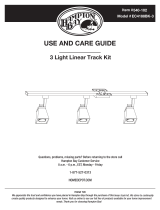
LED Track Kit
Black Finish
White Finish
HOME DEPOT SKU# 939308(UPC#847658003065)
HOME DEPOT SKU# 939044(UPC#847658003058)

2
Thank you for purchasing this Hampton Bay interior LED track kit. This product has been manufactured with the
highest standards of safety and quality.
IMPORTANT SAFETY INSTRUCTIONS
When installing or using this track system, basic safety precautions should always be
followed:
a) Read all instructions.
b) Do not install this track in damp or wet locations.
c) Do not cut any track sections.
d) Do not install any part of a track system less than 7 feet above the floor.
e) Do not install any luminaire assembly closer than 6 inches from any curtain, or
similar combustible material.
f) Disconnect electrical power before adding to or changing the configuration of the
track.
g) Do not attempt to energize anything other than lighting track luminaires on the
track. To reduce the risk of fire and electric shock, do not attempt to connect
power tools, extension cords or appliances to the track.
SAVE THESE INSTRUCTIONS
Rating: 120 volts, single phase, 3-wire with grounded neutral, 60Hz, MAX 5.8W x 3.
Only use HAMPTON BAY's LED TRACK Luminaire model 16031KIT1, MAX 3 pcs .
FEATURES:
1. High output LED that provides a warm light.
2. The swivel design provides 350 degree horizontally and adjustable up to 90 degree vertically.
3. Dimmable.
4. Track luminaire can be located anywhere along the track section.
QUESTION, PROBLEMS, MISSING PARTS:
Before returning to your local Home Depot, please call our Customer Service Team at 1-877-527-0313 or visit
www.homedepot.com. Please reference SKU# ( 939308), UPC (847658003065) or SKU# (939044), UPC
(847658003058).

3
PARTS INCLUDED FOR ASSEMBLY (parts are not to scale):
1pc Floating power canopy 3pcs Track luminaire 1pc 39.37’’ Linear Track
2pcs Toggle bolts 3pcs wire connector 2pcs Plastic anchor
CAUTION:
1. For indoor and dry location use only.
2. LED light cannot be replaced.
3. Do not stare directly into the LED light.
4. To prevent the risk of fire and electric shock, do not attempt to connect power tools, extension cords or
appliances to the track system.
5. FOR USE WITH CEILING-MOUNTED ONLY
READ ALL OF THESE INSTALLATION INSTRUCTIONS BEFORE
INSTALLING THE TRACK SYSTEM.
SAVE THESE INSTRUCTIONS AND REFER TO THEM WHEN ADDITIONS OR
CHANGES IN THE TRACK CONFIGURATION ARE MADE.
INSTALLATION (AS SHOWN IN DIAGRAM):
Fig.1
STEP 1:
CONNECT FLOATING LIVE-END CONNECTOR TO TRACK

4
1. The track section and floating live end connector must be assembled so that polarity between
conductors is maintained. NOTE: The floating live-end connector has a tab on one side of the track
has indentation which runs the length of the track channel (Refer to Fig.2). Align the floating
live-end connector tab with the track indentation and insert the floating live-end connector into the
track channel so that the base of connector fits flush against the track twist connector clockwise 1/4
(one quarter) turn so that the connector fits snugly against the track.
CATUTION: When the floating live-end connector is twisted into position make certain that the two
copper tabs at the base of the connector align with the two copper bars inside the track, this is necessary
to maintain polarity.
2. The floating live-end connector should be positioned along the track so that it will align with the
outlet box after track is installed. The plastic canopy must enclose the floating live-end connector
and cover the outlet box. The plastic canopy should not cover the track mounting attachment holes, it
should attach to the mounting plating with the 2 screws after Electrical connections are made.
STEP 2:
ATTACH MOUNTING PLATE TO TRACK
Place the mounting plate on the back side of the track section so that the set screws on plate fit over the
ridges on both sides of the track. This will insure grounding continuity. Center the plate which previously
installed floating live-end connector and tighten the set screws on both side of the track. Pass wires from
the floating live-end connector through the hole in the mounting plate into ceiling outlet box. (See Fig.3)
Fig. 2 Fig. 3
STEP 3:
ELECTRICAL CONNECTORS
1. When removing the supply wires from the ceiling outlet box, the white supply and black supply wire
should be on one side of the track and green ground wire should be on the other.
2. Connector he white wire from the supply circuit to the white from the floating live-end connector.
Connect the black wire from the supply circuit to the black wire from the floating live-end connector.
Connect the green ground wire from the supply circuit to the green conductor of the floating live-end
connector. Secure splices with UL Listed wire connection suitable for the size, type and number of
conductors. (See Fig. 4)

5
STEP 4:
ATTACHE TRACK TO CEILING
1. Raise the track assembly to the ceiling. Mark the mounting holes locations with a pencil. Insure the
floating live-end connector body is positioned over the ceiling outlet box.
2. Drill hole suitable for the fasteners you will be using. Toggle bolts supplied with the track requires 5/8
inches hole.
3. Insert the toggle bolts through the holes near the ends of the track. Screw bolts into the toggle wings
two or three turns.
4. Push toggle bolts into the holes drilled into the ceiling and tighten toggle bolts until the track is about
1/4 inch from the ceiling. Do not fully tighten toggle bolts until after electrical connections are made.
STEP 5:
INSTALL AND REMOVAL OF TRACK HEAD (REFER TO Fig. 5)
Fig. 4 Fig. 5
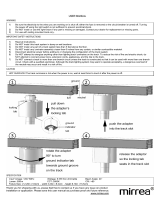
INSTALLATION
1. Push the top portion of the single track luminaire adaptor into the slot of the track section.
2. Pull down the adaptor’s locking tab.
3. Turn the 2 pcs copper conductors 90 degrees towards the ground groove on the track section.
REMOVAL
1. Pull down the adaptor’s locking tab.
2. At the same time, rotate the adaptor 90 degrees and remove from track.
NOTE: ASSEMBLY THE TRIAC DIMMER (REFER TO Fig. 6)
Fig. 6

6
WARNING:
1. This equipment has been tested and found to comply with the limits for a Class B digital
Device pursuant to Part 15 of the FCC Rules. These limits are designed to provide reasonable
protection installation. This equipment generates and can radiate radio frequency energy and,
if not installed and used in accordance with the instructions, may cause harmful interference.
2. However, there is no guarantee that interference will not occur in particular installation. If this
Equipment does cause harmful interference to radio or television reception, which can be determined
By turning the equipment off and on, the user is encouraged to try to correct the interference by one
Or more of the following measures:
● Reorient or relocate the receiving antenna.
● Increase the separation between the equipment and receiver.
● Connect the equipment into a different outlet and circuit from the receiver outlet and circuit.
● Consult the dealer or an experienced radio/TV technician for help.
3. Changes or Modification to this unit not expressly approved by the party responsible for compliance
could void the user's authority to operate the equipment.
LIMITED WARRANTY:
The manufacturer warrants this product to be free from defects in materials and workmanship for a period of three
(3) years from date of purchase. This warranty applies only to the original consumer purchaser and only to products
used in normal use and service. If this product is found to be defective, the manufacturer's only obligation, and your
exclusive remedy, is the repair or replacement of the product at the manufacturer's discretion, provided that the
product has not been damaged through misuse, abuse, accident, modifications, alterations, neglect or mishandling.
This warranty shall not apply to any product that is found to have been improperly installed, set-up, or used in any
way not in accordance with the instructions supplied with the product. This warranty shall not apply to a failure of
the product as a result of an accident, misuse, abuse, negligence, alteration, or faulty installation, or any other
failure not relating to faulty material workmanship. The manufacturer specifically disclaims any liability and shall
not be liable for any consequential or incidental loss or damage, including labor/expense costs involved in the
replacement or repair of said product.

1
MANUAL DE INSTRUCCIONES
Kit LED de Riel
Acabado en Negro
Acabado Blanco
HOME DEPOT NÚM. DE SKU 939308(NÚM. DE UPC847658003065)
HOME DEPOT NÚM. DE SKU 939044 (NÚM. DE UPC847658003058)

3
PIEZAS INCLUIDAS PARA EL ENSAMBLAJE (no se muestran a escala):
1 Cubierta flotante de energía 3 Lámparas de riel 1 Riel lineal de 1 m
2 Pernos acodados 3 conectores de cable 2 Anclajes de plástico
PRECAUCIÓN:
1. Usar sólo en interiores en lugares secos.
2. La lámpara LED no puede reemplazarse.
3. No mires directamente hacia la lámpara LED.
4. Para evitar el riesgo de incendios y descargas eléctricas, no intentes conectar herramientas eléctricas, cables de
extensión o electrodomésticos al sistema de riel.
5. PARA USAR CON EL RIEL DE MONTAJE EN TECHO SOLAMENTE
LEER ESTAS INSTRUCCIONES DE INSTALACIÓN, ANTES DE INSTALAR EL
SISTEMA DE RIEL.
GUARDA ESTAS INSTRUCCIONES Y CONSÚLTALAS CUANDO HAGAS
CAMBIOS O CUANDO AMPLÍES LA CONFIGURACIÓN DEL RIEL.
INSTALACIÓN (COMO SE MUESTRAN EN EL DIAGRAMA):
Fig.1
PASO 1:
CONECTAR AL RIEL EL CONECTOR FLOTANTE DE EXTREMO VIVO

1
MANUEL D'INSTRUCTIONS
Luminaire sur rail
Fini noir
Fini blanc
HOME DEPOT UGS N° 939308(CUP N°847658003065)
HOME DEPOT UGS N° 939044(CUP N°847658003058)
/


