Page is loading ...
Air-Conditioners
SLZ-KA09, KA12, KA15NA
POUR L’INSTALLATEUR
PARA EL INSTALADOR
FOR INSTALLER
INSTALLATION MANUAL
For safe and correct use, please read this manual and the outdoor unit installation manual thoroughly before
installing the air-conditioner unit.
MANUEL D’INSTALLATION
Avant d’installer le climatiseur, lire attentivement ce manuel, ainsi que le manuel d’installation de l’appareil
extérieur pour une utilisation sûre et correct.
MANUAL DE INSTALACIÓN
Para un uso seguro y correcto, lea detalladamente este manual de instalación antes de montar la unidad de
aire acondicionado.
Français
Español
English
2
Contents
1. Safety precautions .....................................................................................2
2. Selecting the installation location ..............................................................3
3. Installation diagram ...................................................................................3
4. Installing the indoor unit ............................................................................3
5. Refrigerant pipe and drain pipe .................................................................6
6. Electrical work ...........................................................................................7
7. Installing the grille ....................................................................................10
8. Test run ....................................................................................................12
1. Safety precautions
1.2. Before installation or relocation
Caution:
• Be extremely careful when transporting the units. Two or more persons are
needed to handle the unit, as it weighs 20 kg, 44 lbs or more. Do not grasp
the packaging bands. Wear protective gloves as you can injure your hands
on the fins or other parts.
• Be sure to safely dispose of the packaging materials. Packaging materials,
such as nails and other metal or wooden parts may cause stabs or other
injuries.
Warning:
• Ask a dealer or an authorized technician to install the unit.
• For installation work, follow the instructions in the Installation Manual and use
tools and pipe components specifically made for use with refrigerant specified
in the outdoor unit installation manual.
• The unit must be installed according to the instructions in order to minimize
the risk of damage from earthquakes, typhoons, or strong winds. An incor-
rectly installed unit may fall down and cause damage or injuries.
• The unit must be securely installed on a structure that can sustain its
weight.
• If the air conditioner is installed in a small room, measures must be taken to
prevent the refrigerant concentration in the room from exceeding the safety
limit in the event of refrigerant leakage. Should the refrigerant leak and cause
the concentration limit to be exceeded, hazards due to lack of oxygen in the
room may result.
• Ventilate the room if refrigerant leaks during operation. If refrigerant comes
into contact with a flame, poisonous gases will be released.
• All electric work must be performed by a qualified technician according to
local regulations and the instructions given in this manual.
• Use only specified cables for wiring.
• The terminal block cover panel of the unit must be firmly attached.
• Use only accessories authorized by Mitsubishi Electric and ask a dealer or
an authorized technician to install them.
• The user should never attempt to repair the unit or transfer it to another loca-
tion.
•
After installation has been completed, check for refrigerant leaks. If refriger-
ant leaks into the room and comes into contact with the flame of a heater or
portable cooking range, poisonous gases will be released.
1.1. Before installation (Environment)
Caution:
• Do not use the unit in an unusual environment. If the air conditioner is installed
in areas exposed to steam, volatile oil (including machine oil), or sulfuric gas,
areas exposed to high salt content such as the seaside, the performance can
be significantly reduced and the internal parts can be damaged.
• Do not install the unit where combustible gases may leak, be produced, flow,
or accumulate. If combustible gas accumulates around the unit, fire or explo-
sion may result.
• Do not keep food, plants, caged pets, artwork, or precision instruments in the
direct airflow of the indoor unit or too close to the unit, as these items can be
damaged by temperature changes or dripping water.
• When the room humidity exceeds 80% or when the drainpipe is clogged,
water may drip from the indoor unit. Do not install the indoor unit where such
dripping can cause damage.
•
When installing the unit in a hospital or communications office, be prepared for
noise and electronic interference. Inverters, home appliances, high-frequency
medical equipment, and radio communications equipment can cause the air
conditioner to malfunction or breakdown. The air conditioner may also affect
medical equipment, disturbing medical care, and communications equipment,
harming the screen display quality.
•
Thermal insulation of the refrigerant pipe is necessary to prevent condensation.
If the refrigerant pipe is not properly insulated, condensation will be formed.
• Place thermal insulation on the pipes to prevent condensation. If the drain-
pipe is installed incorrectly, water leakage and damage to the ceiling, floor,
furniture, or other possessions may result.
•
Do not clean the air conditioner unit with water. Electric shock may result.
• Tighten all flare nuts to specification using a torque wrench. If tightened too
much, the flare nut can break after an extended period.
1.3. Before electric work
Caution:
• Be sure to install circuit breakers. If not installed, electric shock may result.
• For the power lines, use standard cables of sufficient capacity. Otherwise, a
short circuit, overheating, or fire may result.
• When installing the power lines, do not apply tension to the cables.
• Be sure to ground the unit. If the unit is not properly grounded, electric shock
may result.
• Use circuit breakers (ground fault interrupter, isolating switch (+B fuse), and
molded case circuit breaker) with the specified capacity. If the circuit breaker
capacity is larger than the specified capacity, breakdown or fire may result.
1.4. Before starting the test run
Caution:
• Turn on the main power switch more than 12 hours before starting operation.
Starting operation just after turning on the power switch can severely damage
the internal parts.
• Before starting operation, check that all panels, guards and other protective
parts are correctly installed. Rotating, hot, or high voltage parts can cause
injuries.
• Do not operate the air conditioner without the air filter set in place. If the air
filter is not installed, dust may accumulate and breakdown may result.
• Do not touch any switch with wet hands. Electric shock may result.
• Do not touch the refrigerant pipes with bare hands during operation.
• After stopping operation, be sure to wait at least five minutes before turning off
the main power switch. Otherwise, water leakage or breakdown may result.
► Before installing the unit, make sure you read all the “Safety precau-
tions”.
► Please report to your supply authority or obtain their consent before
connecting this equipment to the power supply system.
Warning:
Describes precautions that must be observed to prevent danger of injury or
death to the user.
Caution:
Describes precautions that must be observed to prevent damage to the unit.
After installation work has been completed, explain the “Safety precautions,” use, and
maintenance of the unit to the customer according to the information in the Operation
Manual and perform the test run to ensure normal operation. Both the Installation
Manual and Operation Manual must be given to the user for keeping. These manuals
must be passed on to subsequent users.
: Indicates a part which must be grounded.
Warning:
Carefully read the labels affixed to the main unit.
3
9-1/425/32
25-19/32
25-19/32
2. Selecting the installation location
2.1. Indoor unit
• Where airflow is not blocked.
• Where cool air spreads over the entire room.
• Where it is not exposed to direct sunshine.
• At a distance 1 m, 3 ft or more away from your TV and radio (to prevent picture
from being distorted or noise from being generated).
• In a place as far away as possible from fluorescent and incandescent lights (so
the infrared remote control can operate the air conditioner normally).
• Where the air filter can be removed and replaced easily.
Warning:
Mount the indoor unit into a ceiling strong enough to withstand the weight of
the unit.
3. Installation diagram
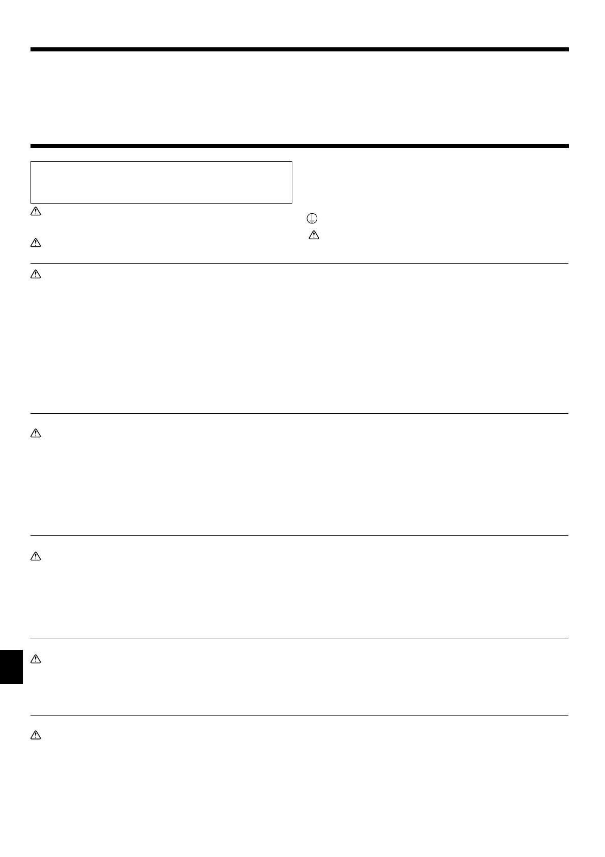
3.1. Indoor unit (Fig. 3-1)
Ceiling
Grille
Obstacle
Min. 1000 mm, 40 inch
Min. 500 mm, 20 inch (Entire periphery)
If setting the maintenance space for
, be sure to leave is a minimum of 700 mm, 28 inch.
Warning:
Mount the indoor unit on a ceiling strong enough to withstand the weight of
the unit.
3.2. Outdoor unit
Refer to the outdoor unit installation manual.
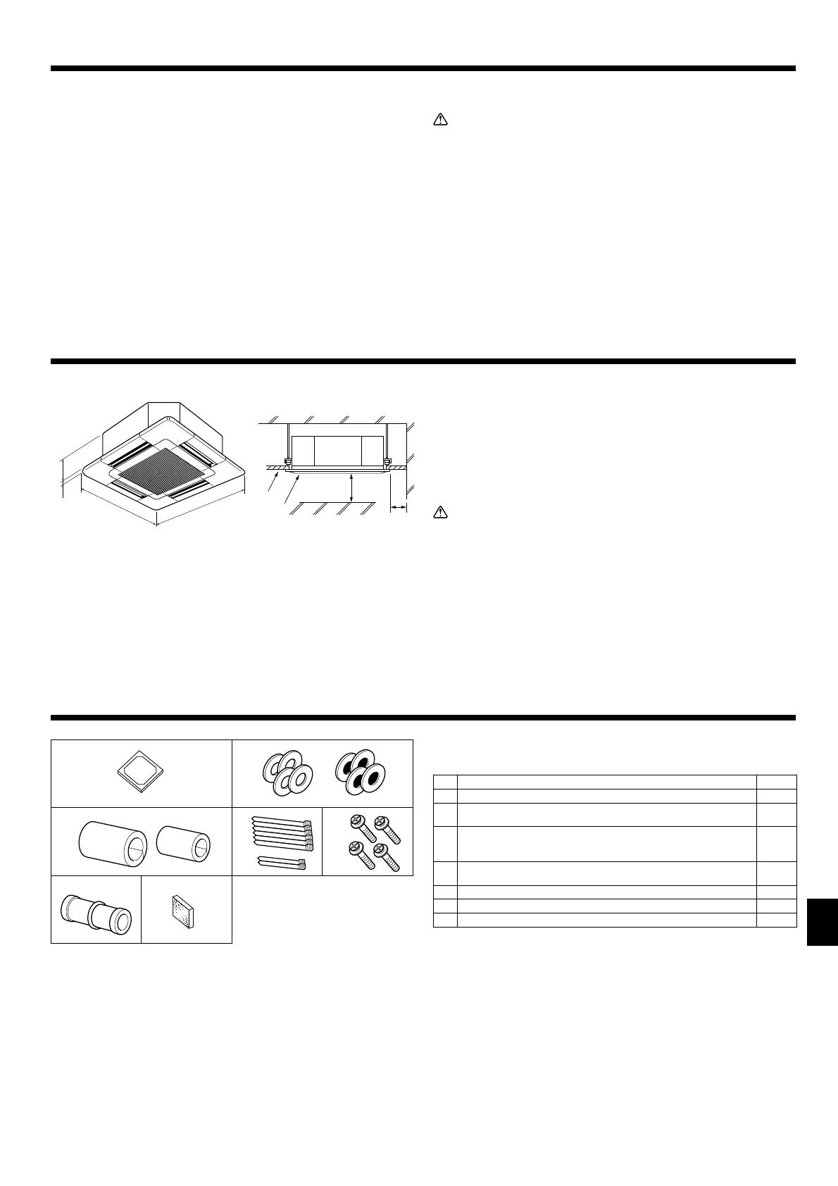
4.1. Check the indoor unit accessories (Fig. 4-1)
The indoor unit should be supplied with the following accessories.
Accessory name Q’ty
Installation template 1
Washers (with insulation)
Washers (without insulation)
4
4
Pipe cover (for refrigerant piping joint)
small diameter (liquid)
large diameter (gas)
1
1
Band (large)
Band (small)
6
2
Screw with washer (M5 × 25) for mounting grille 4
Drain socket 1
Insulation 1
(inch)
Fig. 3-1
Fig. 4-1
4. Installing the indoor unit

4
30
120
120
25/32
2-15/16
3-15/16
2-3/4
19/32
120
120
3-5/8
1
1-1/16
+3/16
0
8-3/16
3-15/16
(22-11/16)
25-19/32
22-11/16 to 24-13/32
1-1/2 to 2-9/32
3-21/32
1-7/8
7-5/32
22-11/16 to 24-13/32
16-17/32
22-7/16
13-3/16
3-7/16
19/32 to 1-15/32
25-19/32
25/32
8-3/16
9-1/4 1/2
40
1-1/16
+3/16
0
20-7/8
13-3/16
22-7/16
Min.18
Min.18 6
13-27/32
7-27/32
19/32 to 1-15/32
19/32 to 1-15/32
(22-11/16)
4.3. Installation of duct (in case of fresh air intake)
(Fig. 4-3)
Caution:
Linkage of duct fan and air conditioner
ln case that a duct fan is used, be sure to make it linked with the air condi-
tioner when outside air is taken.
Do not run the duct fan only. It can cause dew drop.
Making a duct flange (prepared locally)
•
The shape of duct flange shown left is recommended.
Installation of duct flange
• Cut out the cutout hole. Do not knock it out.
• Install a duct flange to the cutout hole of the indoor unit with three 4 × 10 mm, 4 ×
1/2 inch tapping screws which should be prepared locally.
Installation of duct (should be prepared locally)
• Prepare a duct of which inner diameter fits into the outer diameter of the duct
flange.
• In case that the environment above the ceiling is high temperature and high hu-
midity, wrap the duct in a heat insulate to avoid causing dew drop on the wall.
Duct flange recommended shape
3-ø2.8 mm, ø1/8 inch Burring hole
(Thickness: 0.8 mm, 1/32 inch or more)
ø73.4 mm, ø2-7/8 inch cutout hole
3-ø5 mm, ø3/16 inch hole
Duct flange (Prepared locally)
Detail drawing of fresh air intake
4 × 10 mm,
ø
4 × 1/2 inch Tapping screw
(Prepared locally)
Indoor unit
Ceiling surface
Duct
Fig. 4-3
(inch)
4.2. Ceiling openings and suspension bolt installation
locations (Fig. 4-2)
• Using the installation template (top of the package) and the gauge (supplied as
an accessory with the grille), make an opening in the ceiling so that the main unit
can be installed as shown in the diagram. (The method for using the template
and the gauge are shown.)
*
Before using, check the dimensions of template and gauge, because they
change due to fluctuations of temperature and humidity.
* The dimensions of ceiling opening can be regulated within the range shown
in following diagram; so center the main unit against the opening of ceiling,
ensuring that the respective opposite sides on all sides of the clearance be-
tween them becomes identical.
•
Use M10 (3/8") suspension bolts.
* Suspension bolts are to be procured at the field.
• Install securely, ensuring that there is no clearance between the ceiling panel &
grille, and between the main unit & grille.
Outer side of main unit
Min. 500 mm, 20 inch (Entire periphery)
Bolt pitch
If setting the maintenance space for
, be sure to
leave is a minimum of 700 mm, 28 inch.
Ceiling opening
Outer side of Grille
Maintenance space
Grille
Fresh air intake
Ceiling
Angle
Electric component box
* Note that the space between ceiling panel of the unit and ceiling slab, etc., must
be 10 to 15 mm, 3/8 to 9/16 inch to be left.
* Leave the maintenance space at the electric component box end.
Fig. 4-2
(inch)
4. Installing the indoor unit

5
1-1/16
3-21/32
+3/16
0
Min. 1-3/16
Min. 22-11/16
Max. 24-13/32
A=1-1/16
+3/16
0
*B
*B
4. Installing the indoor unit
4.4. Suspension structure (Give site of suspension
strong structure) (Fig. 4-4)
• The ceiling work differs according to the construction of the building. Building
constructors and interior decorators should be consulted for details.
(1) Extent of ceiling removal: The ceiling must be kept completely horizontal and
the ceiling foundation (framework: wooden slats and slat holders) must be rein-
forced in order to protect the ceiling from vibration.
(2) Cut and remove the ceiling foundation.
(3) Reinforce the ends of the ceiling foundation where it has been cut and add ceil
-
ing foundation for securing the ends of the ceiling board.
(4) When installing the unit on a slanting ceiling, interlock a pillow between the ceil-
ing and the grille and set so that the unit is installed horizontally.
Wooden structures
• Use tie beams (single-story houses) or second floor beams (two story houses) as
reinforcing members.
•
Wooden beams for suspending air conditioners must be sturdy and their sides
must be at least 6 cm, 2-3/8 inch long if the beams are separated by not more than
90 cm, 35-7/16 inch and their sides must be at least 9 cm, 3-9/16 inch long if the
beams are separated by as much as 180 cm, 70-7/18 inch. The size of the suspen-
sion bolts should be ø10 mm, 3/8 inch. (The bolts do not come with the unit.)
Ferroconcrete structures
Secure the suspension bolts using the method shown, or use steel or wooden
hangers, etc. to install the suspension bolts.
Unit
Grille
Pillow
Ceiling
Rafter
Beam
Roof beam
Use inserts rated at 100-150 kg, 250-350 lbs
each (procure locally)
Suspension bolts M10 (3/8") (procure locally)
Steel reinforcing rod
Fig. 4-4
Suspension bolt (Procure locally)
Ceiling
Nut (Procure locally)
Washer (with insulation) (Accessory)
Fig. 4-5
Main unit
Ceiling
Installation template (Accessory)
Screw with washer (Accessory)
Fig. 4-7
Fig. 4-6
*B: Suspension bolt pitch (see Fig. 4-2
for details)
Mounting plate
Washer (without insulation) (Accessory)
Check using the Installation gauge
Main unit
Ceiling
Gauge (Grille accessory)
Ceiling opening dimensions
(inch)
4.5. Unit suspension procedures (Fig. 4-5)
Suspend the main unit as shown in the diagram.
1. In advance, set the parts onto the suspension bolts in the order of the washers
(with insulation), washers (without insulation) and nuts (double).
• Fit the washer with cushion so that the insulation faces downward.
• In case of using upper washers to suspend the main unit, the lower washers (with
insulation) and nuts (double) are to be set later.
2. Lift the unit to the proper height of the suspension bolts to insert the mounting
plate between washers and then fasten it securely.
3. When the main unit can not be aligned against the mounting hole on the ceiling,
it is adjustable owing to a slot provided on the mounting plate. (Fig. 4-6)
• Make sure that step A is performed within 27 mm, 1-1/16 inch. Damage
could result by failing to adhere to this range.
4.6. Confirming the position of main unit and tighten-
ing the suspension bolts (Fig. 4-7)
• Using the gauge attached to the grille, ensure that the bottom of the main unit is
properly aligned with the opening of the ceiling. Be sure to confirm this, otherwise
condensation may form and drip due to air leakage etc.
• Confirm that the main unit is horizontally levelled, using a level or a vinyl tube
filled with water.
• After checking the position of the main unit, tighten the nuts of the suspension
bolts securely to fasten the main unit.
• The installation template can be used as a protective sheet to prevent dust from
entering the main unit when the grilles are left unattached for a while or when the
ceiling materials are to be lined after installation of the unit is finished.
*
As for the details of fitting, refer to the instructions given on the Installation template.
+5
0
+3/16
0

6
2-1/4
1-7/32
2-7/32
4-3/4 2-19/32
7-15/16 9-1/16
7-19/32
21/32
45° ± 2°
R1/64 to R1/32
øA
90° ± 0.5°
,
5. Refrigerant pipe and drain pipe
Fig. 5-1
Fig. 5-2
Fig. 5-3
Fig. 5-4
A
As viewed from A
(inch)
5.1. Refrigerant and drainage piping locations of indoor
unit (Fig. 5-1)
Drain pipe
Ceiling
Grille
Refrigerant pipe (liquid)
Refrigerant pipe (gas)
Water supply inlet
Main unit
5.2. Connecting pipes (Fig. 5-2)
• When commercially available copper pipes are used, wrap liquid and gas pipes
with commercially available insulation materials (heat-resistant to 100°C, 212°F or
more, thickness of 12 mm, 1/2 inch or more).
•
The indoor parts of the drain pipe should be wrapped with polyethylene foam insula-
tion materials (specific gravity of 0.03, thickness of 9 mm, 23/64 inch or more).
• Apply thin layer of refrigerant oil to pipe and joint seating surface before tightening
flare nut.
• Use 2 wrenches to tighten piping connections.
• Use refrigerant piping insulation provided to insulate indoor unit connections. Insulate
carefully.
Flare nut tightening torque
Copper pipe O.D. Flare nut O.D. Tightening torque
mm inch mm inch N·m ft - lbs
6.35 1/4 17 43/64 13.7 to 17.7 10 to 13
9.52 3/8 22 7/8 34.3 to 41.2 25 to 30
12.7 1/2 26
1-1/32
49.0 to 56.4 36 to 42
Do not apply refrigerating machine oil to the screw portions.
(This will make the flare nuts more apt to loosen.)
Be certain to use the flare nuts that are attached to the main unit.
(Use of commercially-available products may result in cracking.)
Apply refrigerating machine oil over the entire flare seat surface.
5.3. Indoor unit (Fig. 5-4)
Heat insulation for refrigerant pipes:
Wrap the enclosed large-sized pipe cover around the gas pipe, making sure that
the end of the pipe cover touches the side of the unit.
Wrap the enclosed small-sized pipe cover around the liquid pipe, making sure that
the end of the pipe cover touches the side of the unit.
Secure both ends of each pipe cover with the enclosed bands. (Attach the bands
20 mm, 25/32 inch from the ends of the pipe cover.)
• After connecting the refrigerant piping to the indoor unit, be sure to test the pipe
connections for gas leakage with nitrogen gas. (Check that there is no refrigerant
leakage from the refrigerant piping to the indoor unit.)
Flare cutting dimensions
Copper pipe O.D.
(mm, inch)
Flare dimensions
øA dimensions (mm, inch)
ø6.35, 1/4” 8.7 to 9.1 11/32 to 23/64
ø9.52, 3/8” 12.8 to 13.2 1/2 to 33/64
ø12.7, 1/2” 16.2 to 16.6 41/64 to 21/32
Die
Copper pipe
Copper pipe O.D.
(mm, inch)
A
Flare tool for R410A
Clutch type (mm, inch)
ø6.35, 1/4” 0 to 0.5 0 to 1/64
ø9.52, 3/8” 0 to 0.5 0 to 1/64
ø12.7, 1/2” 0 to 0.5 0 to 1/64
Refrigerant pipe and insulating material
(Procure locally)
Pipe cover (large) (Accessory)
Pipe cover (small) (Accessory)
Refrigerant pipe (gas)
Refrigerant pipe (liquid)
Band (Accessory)
Cross-sectional view of connection
Refrigerant pipe
Insulating material
Squeeze

7
Max. 65ft.
5 to 7 ft
Max. 6 in.
7/16
1-3/16 1-3/16 1-3/16
,
CN105
RED
5. Refrigerant pipe and drain pipe
Fig. 5-5
5.4. Drainage piping work (Fig. 5-5)
• Use VP25 (O. D. ø32 mm, 1-1/4 inch PVC TUBE) for drain piping and provide
1/100 or more downward slope.
• Be sure to connect the piping joints using a polyvinyl type adhesive.
• Observe the figure for piping work.
• Use the included drain hose to change the extraction direction.
Correct piping
Support metal
Wrong piping
Air bleeder
Insulation (9 mm, 3/8 inch or more)
Raised
Downward slope (1/100 or more)
Odor trap
Grouped piping
O. D. ø32 mm, 1-1/4 inch PVC TUBE
Make it as large as possible
Indoor unit
Make the piping size large for grouped piping.
Downward slope (1/100 or more)
O. D. ø38 mm, 1-1/2 inch PVC TUBE for grouped piping.
(9 mm, 3/8 inch or more insulation)
Up to 500 mm, 19-11/16 inch
6. Electrical work
6.1. Indoor unit (Fig. 6-1)
1. Remove 2 screws to detach the electric component cover.
2. Route each cable through the wiring intake into the electric component box.
(Procure power supply cable and control cable locally.)
3. For radio frequency interface
• Connect the electric cord of radio frequency interface securely to CN105 (RED)
on indoor controller board.
For wired remote controller
• Securely connect the power supply cable and control cable to the terminal
blocks.
4. Secure the cables with clamps outside the electric component box.
5. Attach the electric component cover as it was.
• Do not allow slackening of the terminal screws.
• Always install earth.
(Earth cable dia: Thicker than 1.6 mm, 5/8 inch (AWG14))
• Fix power supply cable and control cable to electric component box by using
buffer bushing for tensile force. (PG connection or the like.)
• Tape is affixed over the conduit hole used for connecting the electric wiring.
Please remove this tape if making a connection through the hole.
Fig. 6-1
(inch)
Fig. 5-6
1. Connect the drain socket (supplied with the unit) to the drain port. (Fig. 5-6)
(Affix the tube using PVC adhesive then secure it with a band.)
2. Install a locally purchased drain pipe (PVC pipe, O.D. ø32 mm, 1-1/4 inch).
(Affix the pipe using PVC adhesive then secure it with a band.)
3. Insulate the tube and pipe. (PVC pipe, O.D. ø32 mm, 1-1/4 inch and socket)
4. Check that drain flows smoothly.
5. Insulate the drain port with insulating material, then secure the material with a
band. (Both insulating material and band are supplied with the unit.)
Main unit
Drain pipe (O.D. ø32 mm, 1-1/4 inch PVC TUBE)
Insulating material
Insulating material (purchased locally)
Band (large)
Transparent PVC pipe
Drain port (transparent)
O.D. ø32 mm, 1-1/4 inch PVC TUBE
(Slope 1/100 or more)
Insertion margin
Band (small)
Matching
Drain socket
Electric component cover
Indoor controller board
Electric component box
Power board
Indoor/outdoor unit connecting terminal
Indoor - outdoor connecting cable of Location
Wired remote controller terminal
Remote control cable of Location
8
S3
S3
S2
S1
S2S1
21
CN105
RED
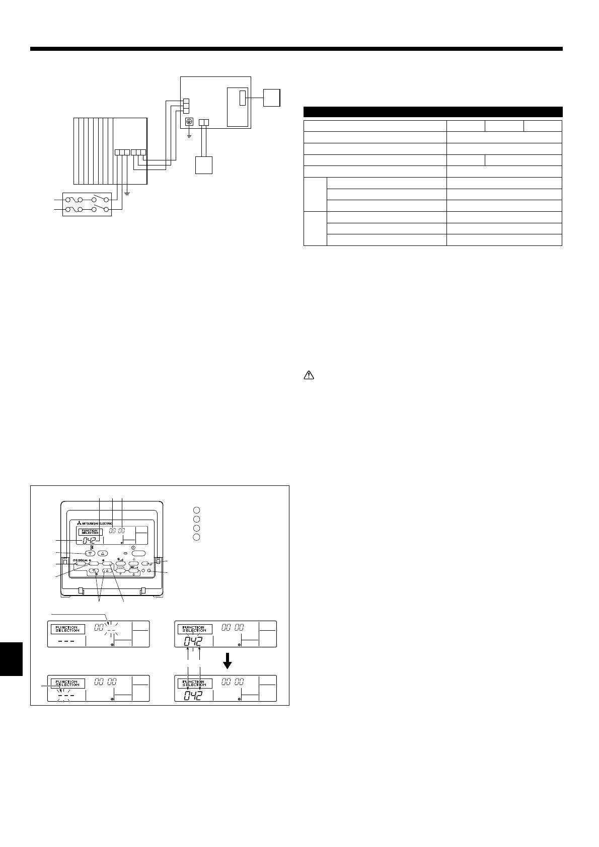
6.1.1. Indoor unit power supplied from outdoor unit (Fig. 6-2)
The following connection patterns are available.
The outdoor unit power supply patterns vary on models.
1 : 1 System
Indoor unit model SLZ-KA09 SLZ-KA12 SLZ-KA15
Power supply Single, 208/230V, 60Hz
Min. circuit ampacity 1 A
Fan motor (F.L.A) 0.23 A 0.28 A
Input capacity main switch/fuse 15 A
Wiring
Wire No. ×
size
Indoor unit - Outdoor unit *1 3 × AWG 14 (Polar)
Indoor unit - Outdoor unit earth 1 × Min. AWG 16
Wired remote controller - Indoor unit *2 2 × AWG 22 (Non-polar)
Circuit rat-
ing
Indoor unit - Outdoor unit S1-S2 *3 AC 208/230 V
Indoor unit - Outdoor unit S2-S3 *3 DC 24 V
Wired remote controller - Indoor unit *3 DC 12 V
*1
Max. 50 m, 165 ft
*2 The 10 m, 30 ft wire is attached in the wired remote controller accessory. Max. 500 m, 1500
ft.
*3 The figures are NOT always against the ground.
S3 terminal has DC24V against S2 terminal. However between S3 and S1, these terminals
are not electrically be the transformer or other device.
Note:
1. Wiring size must comply with the applicable local and national code.
2. Use copper supply wires.
3. Use wires rated 600V or more for the power supply cables and the indoor
unit/outdoor unit connecting cables.
4. Install an earth longer than other cables.
Caution:
• Use care not to make miswiring.
• Firmly tighten the terminal screws to prevent them from loosening.
• After tightening, pull the wires lightly to confirm that they do not move.
Fig. 6-2
Indoor unit
Outdoor unit
Wired remote controller
Main switch/fuse
Grounding
Indoor controller board
Radio frequency interface for RF thermostat
For Power supply
6. Electrical work
6.2. Remote controller
6.2.1. Wired remote controller
1) 2 remote controllers setting
If 2 remote controllers are connected, set one to “Main” and the other to “Sub”. For
setting procedures, refer to “Function selection of remote controller” in the opera-
tion manual for the indoor unit.
Fig. 6-3
Mode number
Setting number
Refrigerant address
Unit number
6.3. Function settings
For wired remote controller only (Fig. 6-3)
Changing the power voltage setting
• Be sure to change the power voltage setting depending on the voltage used.
Go to the function setting mode.
Switch OFF the wired remote controller.
Press the
and
buttons simultaneously and hold them for at least 2
seconds. FUNCTION will start to flash.
Use the
button to set the refrigerant address (
) to 00.
Press
and [--] will start to flash in the unit number (
) display.
Use the
button to set the unit number (
) to 00.
Press the
MODE button to designate the refrigerant address/unit number. [--]
will flash in the mode number (
) display momentarily.
Press the
buttons to set the mode number (
) to 04.
Press the
button and the current set setting number (
) will flash.
Use the
button to switch the setting number in response to the power supply
voltage to be used.
Power supply voltage
230 V : setting number = 1
208 V : setting number = 2
Press the MODE button
and mode and the setting number (
) and (
) will
change to being on constantly and the contents of the setting can be confirmed.
Press the FILTER
and TEST RUN
buttons simultaneously for at least two
seconds. The function selection screen will disappear momentarily and the air
conditioner OFF display will appear.
PAR-21MAA
ON/OFF
FILTER
CHECK
OPERATION
CLEAR
TEST
TEMP.
MENU
BACK DAY
MONITOR/SET
CLOCK
ON/OFF
9
6. Electrical work
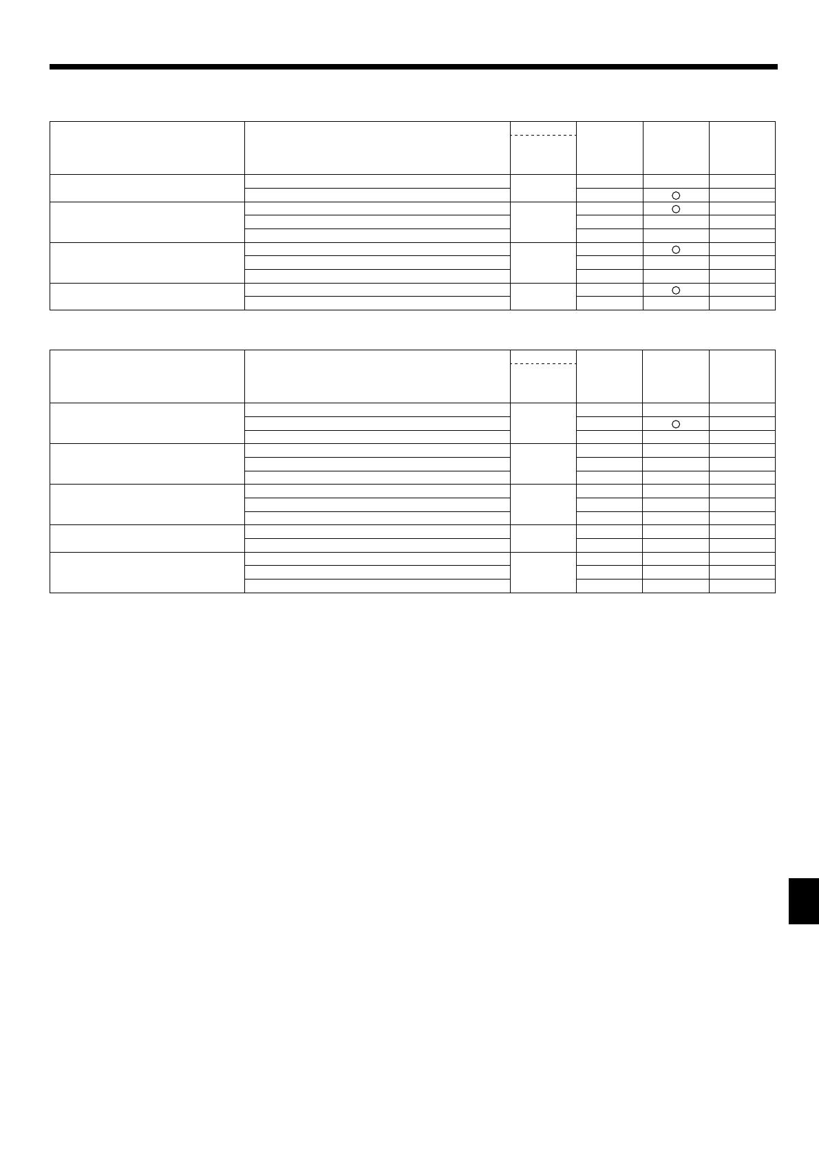
Function table
Select unit number 00
Mode Settings
Mode No.
Setting no. Initial setting Setting
Wired remote
controller
(RF thermostat)
Power failure automatic recovery
(AUTO RESTART FUNCTION)
Not available
01
(101)
1
Available 2
Indoor temperature detecting Indoor unit operating average
02
(–)
1
Set by indoor unit’s remote controller 2
Wired remote controller’s internal sensor 3
LOSSNAY connectivity Not Supported
03
(103)
1
Supported (indoor unit is not equipped with outdoor-air intake) 2
Supported (indoor unit is equipped with outdoor-air intake) 3
Power voltage 230 V
04
(104)
1
208 V 2
Select unit numbers 01 to 03 or all units (AL [wired remote controller]/07 [wireless remote controller])
Mode Settings
Mode No.
Setting no. Initial setting Setting
Wired remote
controller
(RF thermostat)
Filter sign 100 Hr
07
(107)
1
2500 Hr 2
No filter sign indicator 3
Fan speed Standard (PLH/PLA)/Silent (PCH/PCA)
08
(108)
1—
High ceiling
(PLH/PLA)/Standard (PCH/PCA) 2 —
High ceiling
(PLH/PLA)/High ceiling (PCH/PCA) 3 —
No. of air outlets 4 directions
09
(109)
1—
3 directions 2 —
2 directions 3 —
Installed options (high-performance filter) Not supported
10
(110)
1—
Supported 2—
Up/down vane setting No vanes
11
(111)
1—
Equipped with vanes (vanes angle setup
)2—
Equipped with vanes (vanes angle setup
)3—

10
A=1-1/16
Min.22-11/16
Min.24-13/32
+3/16
0
19/32
to
25/32
Fig. 7-3
Fig. 7-4
7.2. Preparing to attach the grille (Fig. 7-2)
• With the gauge supplied with this kit, adjust and check the positioning of the unit
relative to the ceiling. If the unit is not properly positioned in the ceiling, there
may be air leaks, condensation may form, or the up/down vanes may not operate
correctly.
•
Make sure that the opening in the ceiling is within the following tolerances:
576 × 576 - 620 × 620 mm, 22-11/16 × 22-11/16 inch to 24-13/32 × 24-13/32 inch.
• Make sure that step A is performed within 27-32 mm, 1-1/16 to 1-1/4 inch. Dam-
age could result by failing to adhere to this range.
Main unit
Ceiling
Gauge (Accessory)
Ceiling opening dimensions
7.2.1. Removing the intake grille (Fig. 7-3)
• Slide the levers in the direction indicated by the arrow
to open the intake grille.
• Unlatch the hook that secures the grille.
* Do not unlatch the hook for the intake grille.
• With the intake grille in the “open” position, remove the hinge of the intake grille
from the grille as indicated by the arrow
.
Fig. 7-2
7.3. Installing the grille
• Please pay attention because there is a restriction in the attachment position of
the grille.
7.3.1. Preparations (Fig. 7-5)
• Install the 2 enclosed screws with washer in the main unit (at the corner refriger-
ant pipe area and at the opposite corner) as shown in the diagram.
Main unit
Detailed diagram of installed screw with washer (accessory).
(inch)
Fig. 7-5
7.2.2. Removing the corner panel (Fig. 7-4)
• Remove the screw from the corner of the corner panel. Slide the corner panel as
indicated by the arrow
to remove the corner panel.
Intake grille
Hole for the grille’s hook
Grille
Corner panel
Intake grille levers
Screw
Grille hook
7.1. Check the grille accessories (Fig. 7-1)
• The grille should be supplied with the following accessories.
Accessory name Q’ty Remark (mm, inch)
Grille 1 650 × 650 , 25-19/32 × 25-19/32
Screw with washer 4 M5 × 0.8 × 25, M5 × 1/32 × 31/32
Gauge 1
Fastener 2
Band 2
7. Installing the grille
Fig. 7-1
(inch)

11
A
Fig. 7-8
7.4. Locking the up/down airflow direction (Fig. 7-9)
The vanes of the unit can be set and locked in on up or down orientation depending
upon the environment of use.
• Set according to the preference of the customer.
The operation of the fixed up/down vanes and all automatic controls cannot
be performed using the remote controller. In addition, the actual position of the
vanes may differ from the position indicated on the wired remote controller.
Turn off the main power switch.
Injuries and or an electrical shock may occur while the fan of the unit is rotating.
Disconnect the connector for the vane motor of the vent that you want to lock.
(While pressing the button, remove the connector in the direction indicated by
the arrow as shown in the diagram.) After removing the connector, insulate it
with tape.
To adjust the desired airflow direction, slowly move the up/down vanes within
the specified range. (Fig. 7-10)
Specified range
Up/down airflow
direction
Horizontal 30°
Downward 45° Downward 55° Downward 70°
A
21 mm
13/16 inch
25 mm
31/32 inch
28 mm
1-3/32 inch
30 mm
1-3/16 inch
•
The vanes can be set between 21 and 30 mm (13/16 and 1-3/16 inch).
Caution:
Do not set the up/down vanes passed the specified range. Condensation
could form on and drop from the ceiling, or the unit could malfunction.
Fig. 7-9
Button
Vane motor
Up/down vanes
Connector
Fig. 7-10
7.3.4. Wire connection (Fig. 7-8)
• Be sure to connect the unit to the connector (white: 10-pole/red: 9-pole). Next,
attach the white glass tube that comes with the main unit so that the tube covers
the connector. Close the opening of the glass tube with the band.
•
Make sure that there is no slack in the each lead wire at the fastener on the grille.
Fastener (Accessory)
White glass tube
Connector of the main unit
Connector of the grille
Band (Accessory)
Measurement standard
position of grille
Up/down vanes
7. Installing the grille
7.3.2. Temporary installation of the grille (Fig. 7-6)
• Align the electric component box of the main unit and the receiver of the grille,
and then temporarily secure the grille using the bell shaped holes.
* Make sure that the lead wiring of the grille does not get pinched between the
grille and the main unit.
Main unit
Electric component box
Screw with washer (for temporary use)
Screw with washer (Accessory)
Grille
Bell shaped hole
7.3.3. Securing the grille (Fig. 7-7)
• Secure the grille to the main unit by tightening the previously installed 2 screws
(with captive washer) as well as the 2 remaining screws (with captive washer).
* Make sure that there are no gaps between the main unit and the grille or the
grille and the ceiling.
Ceiling
Main unit
Grille
Make sure that there are no gaps.
Fig. 7-6
Fig. 7-7
12
8. Test run
8.1. Before test run
► After installation of indoor and outdoor units, and piping and electric wir-
ing work, recheck that the unit is free from leaks of refrigerant, loosened
connections, and incorrect polarity.
►
Measure an impedance between the power supply terminal block (L, N,
)
on the units and the ground with a 500 V Megger and check that it is equal
to or greater than 1.0 MΩ.
7. Installing the grille
Fig. 7-11
7.5. Installing the intake grille (Fig. 7-11)
• Perform the procedure that is described in “7.2. Preparing to attach the grille” in
reverse order to install the intake grille and the corner panel.
Refrigerant piping of the main unit
Drain piping of the main unit
Corner panel
* Installation in any position is possible.
Position of the levers on the intake grille when sent from the factory.
* Although the clips can be installed in any of four positions.
7.6. Check
• Make sure that there is no gap between the unit and the grille, or between the
grille and the surface of the ceiling. If there is any gap between the unit and the
grille, or between the grille and the surface of the ceiling, it may cause dew to
collect.
•
Make sure that the wires have been securely connected.
8.2. Test run
■
Refer to the installation manual that comes with each remote controller for de-
tails.
8.3. Self-check
■
Refer to the installation manual that comes with each remote controller for de-
tails.
■
RF thermostat is not established.
Errors detected by indoor unit
Wired remote controller
RF thermostat
Symptom Remark
Check code
P1 Intake sensor error
P2 Pipe (TH2) sensor error
P9 Pipe (TH5) sensor error
E6, E7 Indoor/outdoor unit communication error
P4 Drain sensor error
P5 Drain pump error
PA Forced compressor error
P6 Freezing/Overheating safeguard operation
EE Communication error between indoor and outdoor units
P8 Pipe temperature error
E4 Remote controller signal receiving error
Fb Indoor unit control system error (memory error, etc.)
Errors detected by unit other than indoor unit (outdoor unit, etc.)
Wired remote controller
RF thermostat
Symptom Remark
Check code
E9 Indoor/outdoor unit communication error (Transmitting error) (Outdoor unit)
For details, check the LED dis-
play of the outdoor controller
board.
UP Compressor overcurrent interruption
U3, U4 Open/short of outdoor unit thermistors
UF Compressor overcurrent interruption (When compressor locked)
U2 Abnormal
high discharging temperature/49C worked/insufficient refrigerant
U1, Ud Abnormal high pressure (63H worked)/Overheating safeguard operation
U5 Abnormal temperature of heat sink
U8 Outdoor unit fan safeguard stop
U6 Compressor overcurrent interruption/Abnormal of power module
U7 Abnormality of super heat due to low discharge temperature
U9, UH
Abnormality such as overvoltage or voltage shortage and abnormal synchronous signal to
main circuit/Current sensor error

13
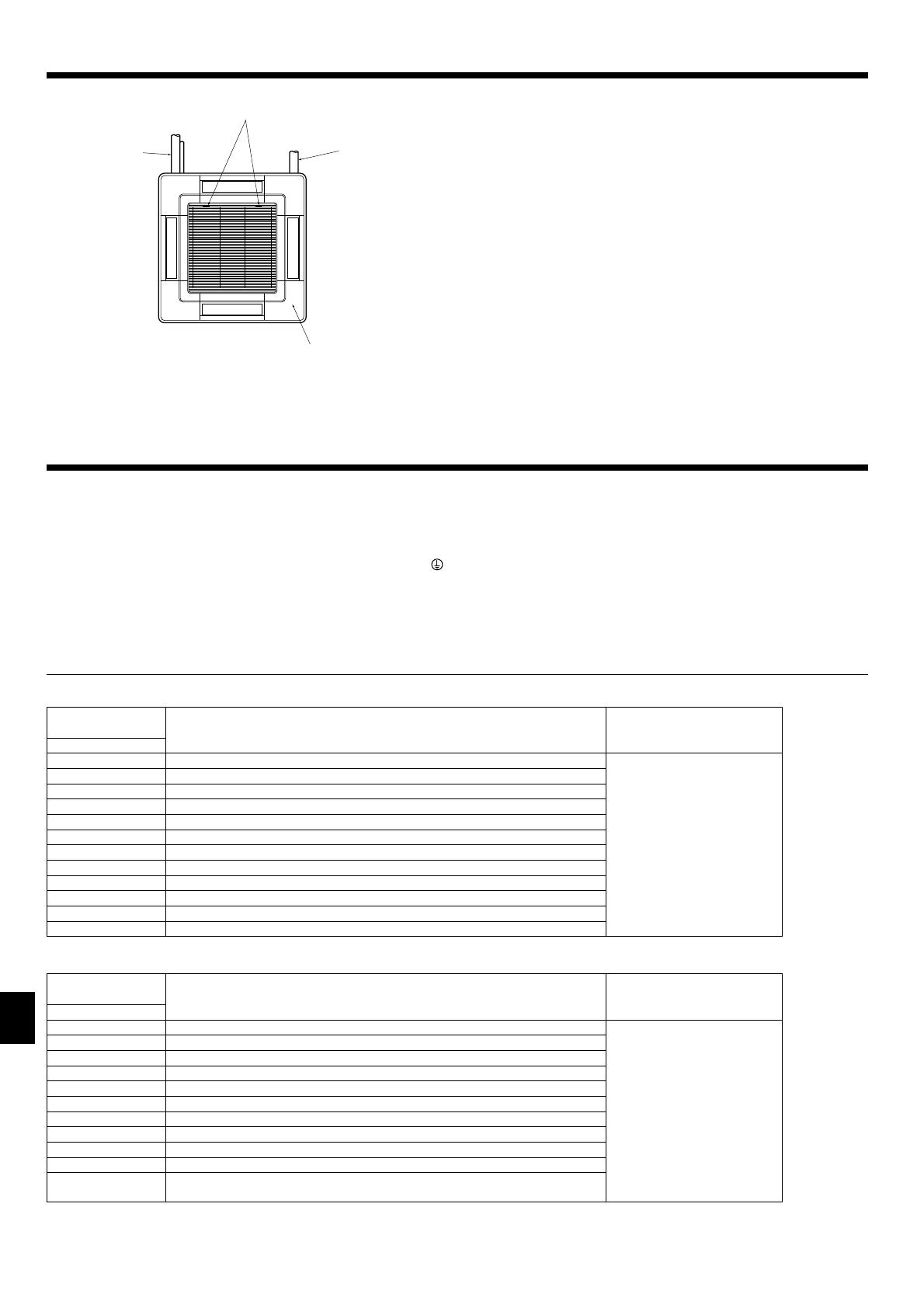
Fig. 8-1
8. Test run
8.4. Check drainage
(Fig. 8-1)
• During the test run, ensure the water is being properly drained out and that no
water is leaking from joints.
• Always check this during installation even if the unit is not required to provide
cooling/drying at that time.
• Similarly, check the drainage before finishing ceiling installation in a new premis-
es.
(1)
Remove the cover of the water supply inlet and add about 1000 cc, 1/4 gal of
water using a water supply pump etc. During this process, be careful not to
spray water into the drain pump mechanism.
(2) Confirm that water is being drained out through the drainage outlet, after switch-
ing over from remote control mode to test run mode (cooling mode).
(3)
After checking the drainage, ensure that the cover is replaced and the power
supply is isolated.
(4) After confirming the drainage system is functioning, replace the drain plug.
Insert the pump end 3 to 5 cm, 1-3/16 to 2 inch
Water
Cover of water supply inlet
Drain plug
About 1000 cc, 1/4 gal
• On wired remote controller
Check code displayed in the LCD.
• If the unit cannot be operated properly after the above test run has been performed, refer to the following table to remove the cause.
Note:
Operation is not possible for about 30 seconds after cancellation of function selection. (Correct operation)
For description of each LED (LED1, 2, 3) provided on the indoor controller, refer to the following table.
LED1 (power for microcomputer) Indicates whether control power is supplied. Make sure that this LED is always lit.
LED2 (power for wired remote controller) Indicates whether power is supplied to the wired remote controller.
LED3 (communication between indoor and outdoor units)
Indicates state of communication between the indoor and outdoor units. Make sure that this LED
is always blinking.
Symptom
Cause
Wired remote controller/ RF thermostat
PLEASE WAIT
For about 2 minutes
following power-on
•
For about 2 minutes following power-on, operation of the remote controller is not
possible due to system start-up. (Correct operation)
PLEASE WAIT → Error code
After about 2 minutes
has expired following
power-on
• Connector for the outdoor unit’s protection device is not connected.
• Reverse or open phase wiring for the outdoor unit’s power terminal block
Display messages do not appear even
when operation switch is turned ON
• Incorrect wiring between indoor and outdoor units (incorrect polarity of S1, S2, S3)
• Remote controller wire short
HEAD OFFICE: TOKYO BLDG., 2-7-3, MARUNOUCHI, CHIYODA-KU, TOKYO 100-8310, JAPAN
Please be sure to put the contact address/telephone number on
this manual before handing it to the customer.
This product is designed and intended for use in the residential,
commercial and light-industrial environment.
RG79D589H01 Printed in Thailand
/