2
Important Safety Instructions
This manual contains information concerning the proper installation and
use of Tripp Lite’s Rackmount Power Strips.
SAVE THESE INSTRUCTIONS.
Do not connect your power strip to an ungrounded outlet. Do not use it with extension
cords or adapters that eliminate its connection to ground. Your power strip is designed
for indoor use only. Install it away from heat emitting devices such as radiators and heat
registers. Do not install where excessive moisture or other conductive contaminants are
present. Never install electrical wiring during a lightning storm.
The power requirement of each device connected to an outlet of your power strip must
not exceed the Outlet Power Rating of your power strip (see Specifications). The total
power requirements of all devices connected to your power strip must not exceed the
Maximum Load Rating of your power strip (see Specifications).
Installation
1U Rackmount Installation
0U Rackmount Installation
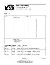
1U Rackmount Installation
To Mount Unit in Rack: Put four user-supplied
rackmount screws (A) through the unit’s mounting
ears (B) and into the rack rails as shown. The user
must determine the fitness of the rackmount screws to
hold the unit in the rack before installation.
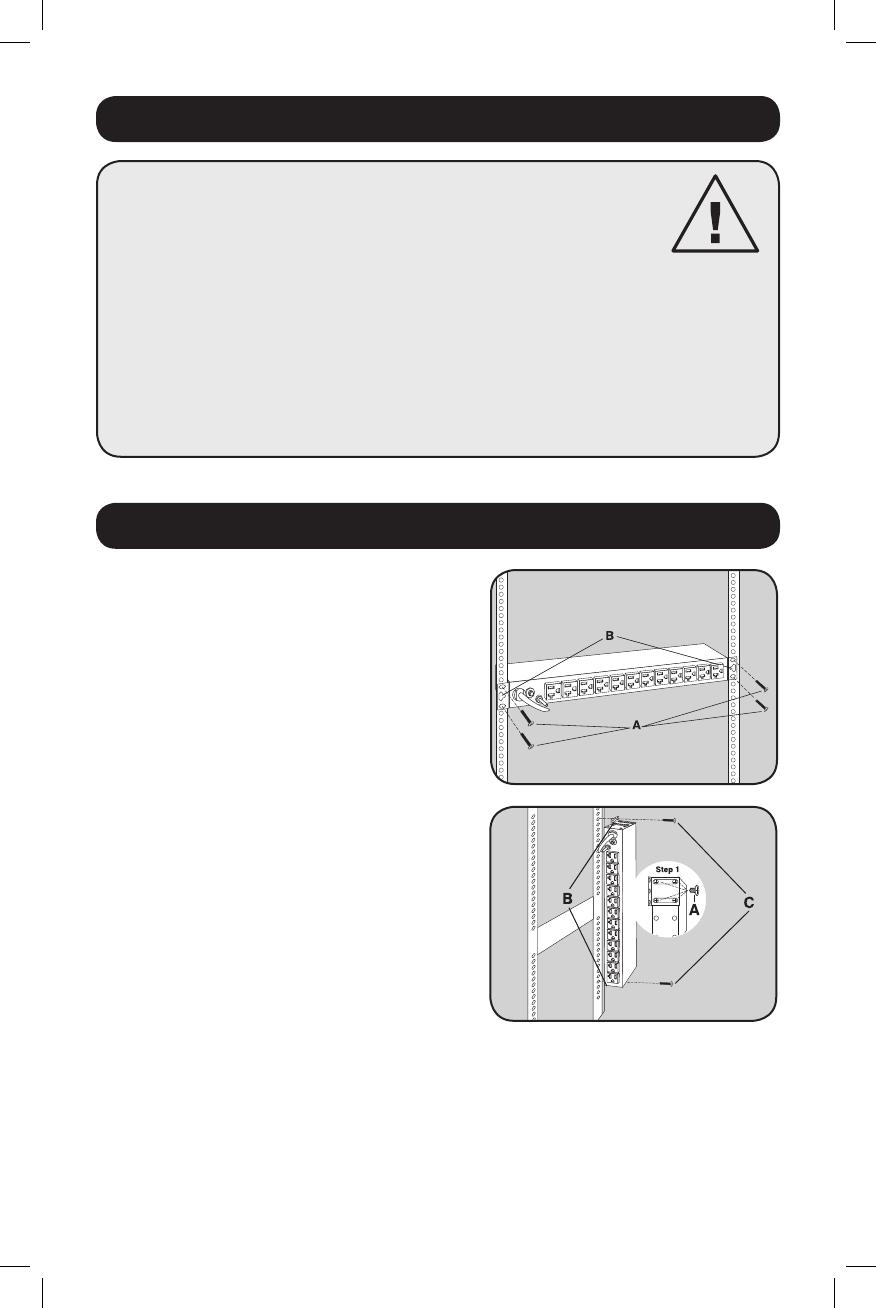
0U Rackmount Installation
1. Reorient Mounting Ears: Unscrew the screws (A)
holding the unit’s mounting ears (B) to the sides of
the unit. Use the screws from Step 1 (A) to reattach
the mounting ears (B) to the unit as shown. Use
only the manufacturer-supplied screws or their
equivalent (#6-32, ¼” flat head) to reattach the
mounting ears.
2. Mount Unit on Outside of Rack Rails: Put four
user-supplied screws (C) or similar mounting
hardware through the unit’s mounting ears (B) and
into the side of the rack as shown. The user must
determine the fitness of the user-supplied mounting
hardware to support the unit before mounting.
Wallmount/Under Counter Installation
Reorient the unit’s mounting ears as per the 0U Rackmount Installation above, then put four user-
supplied screws or similar mounting hardware through the unit’s mounting ears and into the
mounting surface. The user must determine the fitness of the user-supplied mounting hardware to
support the unit before mounting.
14-02-325-932120.indb 2 3/25/2014 4:19:39 PM