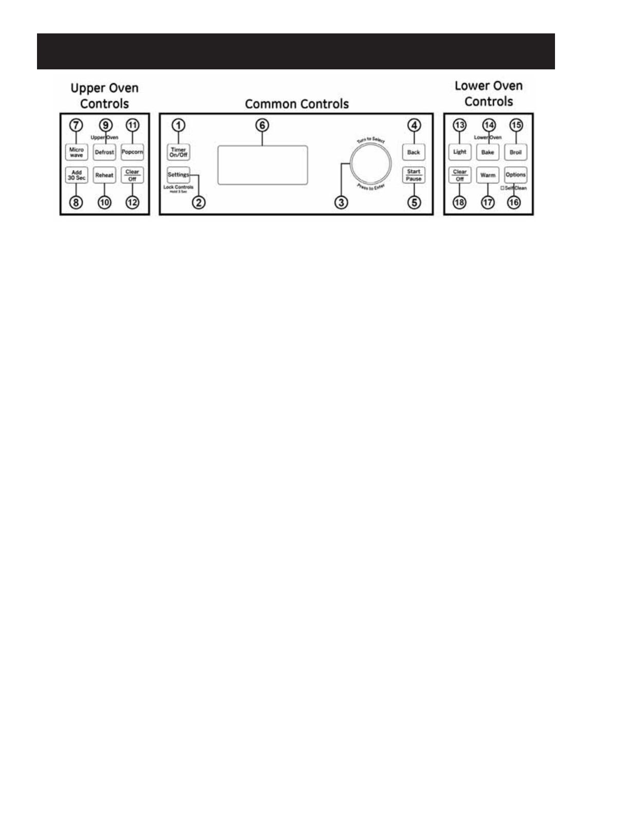
GE JK3800DH1WW Technical Service Manual

Category
Microwaves
Type
Technical Service Manual
GE Appliances
General Electric Company
Louisville, Kentucky 40225
31-9239
Combination Wall Oven
Technical Service Guide
March 2015
GE Appliances
27”
JK3800DH1BB
JK3800DH1WW
JK3800SH1SS
JK3800DH2BB
JK3800DH2WW
JK3800SH2SS
30”
JT3800DH1BB
JT3800SH1SS
JT3800DH2BB
JT3800SH2SS
PT7800DH1BB
PT7800DH1WW
PT7800SH1SS
PT7800DH2BB
PT7800DH2WW
PT7800SH2SS
PT9800SH1SS
PT9800SH2SS
CT9800SH1SS
– 2 –
IMPORTANT SAFETY NOTICE
The information in this service guide is intended for use by
individuals possessing adequate backgrounds of electrical,
electronic, and mechanical experience. Any attempt to repair a
major appliance may result in personal injury and property
damage. The manufacturer or seller cannot be responsible for the
interpretation of this information, nor can it assume any liability in
connection with its use.
WARNING
To avoid personal injury, disconnect power before servicing
this product. If electrical power is required for diagnosis or test
purposes, disconnect the power immediately after performing the
necessary checks.
RECONNECT ALL GROUNDING DEVICES
If grounding wires, screws, straps, clips, nuts, or washers used to
complete a path to ground are removed for service, they must be
returned to their original position and properly fastened.
GE Appliances
Technical Service Guide
Copyright © 2015
All rights reserved. This service guide may not be reproduced in whole or in part
in any form without written permission from the General Electric Company.
– 3 –
Table of Contents
Safety Requirements .....................................................................................................................................................................6
Introduction .......................................................................................................................................................................................8
Additional Service Information ..................................................................................................................................................9
Nomenclature ...................................................................................................................................................................................10
3URGXFW6SHFL¿FDWLRQV ..................................................................................................................................................................11
,QVWDOODWLRQ(OHFWULFDO6SHFL¿FDWLRQV .......................................................................................................................................11
Accessories ................................................................................................................... ......................................................................11
Tools Needed .....................................................................................................................................................................................12
Service Harness Extension ..........................................................................................................................................................13
'H¿QLWLRQV ...........................................................................................................................................................................................14
Installation .........................................................................................................................................................................................15
Owner's Manuals Information ...................................................................................................................................................17
Oven Controls 3800 Series ..................................................................................................................................................18
Oven Controls 7800 Series ..................................................................................................................................................20
Oven Controls 9800 Series ..................................................................................................................................................22
Oven Settings ............................................................................................................................................................................24
Oven Options.............................................................................................................................................................................25
Lower Oven Cooking Modes ..............................................................................................................................................27
Sabbath Mode ..........................................................................................................................................................................29
$LUÀRZ ...................................................................................................................................................................................................31
Speedcook Operation ....................................................................................................................................................................32
Upper Oven Components ............................................................................................................................................................34
Door Assembly .........................................................................................................................................................................34
Control Panel Assembly .......................................................................................................................................................35
Control Boards and Panel Connections ................................................................................................................................36
Removing Upper Oven ..................................................................................................................................................................42
Upper Oven Electrical Components .......................................................................................................................................43
Upper Heater and Oven Cavity TCO's ............................................................................................................................43
Lower Heater Assembly .......................................................................................................................................................43
Humidity Sensor ......................................................................................................................................................................44
Turntable Motor ........................................................................................................................................................................44
– 4 –
Convection Heater Assembly and Thermistor ...........................................................................................................45
Upper Heater Assembly .......................................................................................................................................................45
Blower Assembly .....................................................................................................................................................................46
Convection Heater Element ...............................................................................................................................................47
Convection Fan Motor ..........................................................................................................................................................48
Damper Assembly...................................................................................................................................................................48
Damper Door Switch .............................................................................................................................................................49
Magnetron and Magnetron TCO ......................................................................................................................................49
High Voltage Transformer ...................................................................................................................................................50
Left and Right Door Switch Assemblies ........................................................................................................................50
Noise Filter ..................................................................................................................................................................................53
Surge Board ...............................................................................................................................................................................54
Capacitor and Diode ..............................................................................................................................................................54
Cavity Light ................................................................................................................................................................................55
Proof Feature Upper oven ...................................................................................................................................................55
Microwave Leak Test .............................................................................................................................................................56
Standard Test Load ................................................................................................................................................................56
Demo Mode ...............................................................................................................................................................................57
Schematic Diagram .......................................................................................................................................................................58
Lower Oven Structural Components ......................................................................................................................................59
Door Assembly .........................................................................................................................................................................60
Gasket...........................................................................................................................................................................................61
Vertical Brace ............................................................................................................................................................................61
Lower Oven Electrical Components .......................................................................................................................................64
Cooling Fan Motor ..................................................................................................................................................................64
Cooling Fan Motor Reinstallation.....................................................................................................................................65
L2 High Limit Switch ..............................................................................................................................................................65
Oven Sensor ..............................................................................................................................................................................66
Lock Assembly ..........................................................................................................................................................................66
Elements ......................................................................................................................................................................................67
Hidden Bake ..............................................................................................................................................................................67
Broil ......................................................................................................................... .......................................................................68
– 5 –
Convection Element ...............................................................................................................................................................69
Diagnostics ................................................................................................................... ......................................................................70
Software Versions / Fault Codes ......................................................................................................................................70
Troubleshooting Lower Oven .....................................................................................................................................................71
Accessing Machine Control Board/Bridge Board .............................................................................................................72
Service Mode .............................................................................................................................................................................74
GE Wall Oven Warranty ................................................................................................................................................................76
– 6 –
Safety Requirements
GE Factory Service Employees are required to use safety glasses with side shields, safety gloves and
steel toe shoes for all repairs.
Steel Toed Work Boot
Electrically Rated Glove and
Dyneema® Cut Resistant
Glove Keeper
Dyneema®Cut Resistant
Glove
Plano Type Safety Glasses
Prescription Safety Glasses
Safety Glasses must be ANSI
Z87.1-2003 compliant
Brazing Glasses
Cut Resistant Sleeve(s)
Prior to disassembly of the oven to access components, GE Factory
Service technicians are REQUIRED to follow the Lockout / Tagout
(LOTO) 6 Step Process:
Step 1
Plan and Prepare
Step 4
Apply LOTO device and lock
Step 2
Shut down the appliance
Step 5
Control (discharge) stored energy
Step 3
Isolate the appliance
Step 6
Try It” verify that the appliance is
locked out
– 7 –
PRECAUTIONS TO BE OBSERVED BEFORE AND DURING SERVICING TO AVOID POSSIBLE EXPOSURE TO
EXCESSIVE MICROWAVE ENERGY.
A. DO NOT OPERATE OR ALLOW THE OVEN TO BE OPERATED WITH THE DOOR OPEN.
B. IF THE OVEN OPERATES WITH THE DOOR OPEN, INSTRUCT THE USER NOT TO OPERATE THE OVEN AND
CONTACT THE MANUFACTURER IMMEDIATELY.
C. MAKE THE FOLLOWING SAFETY CHECKS ON ALL OVENS TO BE SERVICED BEFORE ACTIVATING THE
MAGNETRON OR OTHER MICROWAVE SOURCE, AND MAKE REPAIRS AS NECESSARY:
1. INTERLOCK OPERATION
2. PROPER DOOR CLOSING
3. SEAL AND SEALING SURFACES (ARCING, WEAR AND OTHER DAMAGE)
4. DAMAGE TO OR LOOSENING OF HINGES AND LATCHES
5. EVIDENCE OF DROPPING OR ABUSE
D. BEFORE TURNING ON MICROWAVE POWER FOR ANY TEST OR INSPECTION WITHIN THE MICROWAVE
GENERATING COMPARTMENTS, CHECK THE MAGNETRON, WAVE GUIDE OR TRANSMISSION LINE AND
CAVITY FOR PROPER ALIGNMENT, INTEGRITY AND CONNECTIONS.
E. ANY DEFECTIVE OR MISADJUSTED COMPONENTS IN THE INTERLOCK MONITOR, DOOR SEAL AND
MICROWAVE GENERATION AND TRANSMISSION SYSTEMS SHALL BE REPAIRED, REPLACED OR ADJUSTED
BY PROCEDURE DESCRIBED IN THIS MANUAL BEFORE THE OVEN IS RELEASED TO THE OWNER.
F. A MICROWAVE LEAKAGE CHECK TO VERIFY COMPLIANCE WITH THE FEDERAL PERFORMANCE STANDARD
SHOULD BE PERFORMED ON EACH OVEN PRIOR TO RELEASE TO THE OWNER.
– 8 –
GE’s Updated Combination Wall Ovens
GE has introduced the new versions of 27 inch and 30 inch combination wall ovens. In addition, an
Advantium® model was added to the wall oven line. The Advantium® oven uses Speedcook technology
to harness the power of light. The Advantium® oven cooks the outside of foods much like conventional
radiant heat, while also penetrating the surface so the inside cooks simultaneously. While halogen light is
the primary source of power, a "microwave boost” is added with certain foods. Foods cook evenly and fast,
retaining their natural moisture.
JK3800: 27” with microwave and conventional lower self-clean oven
JT3800: 30” with microwave and conventional lower self-clean oven
PT7800: 30” with convection microwave and convection lower self-clean oven
PT9800/CT9800: 30” with Advantium® oven and convection lower self-clean oven
Common Features:
Menu Driven Control: With 4 line graphical display.
Panelized Cavities: 4.3 cu ft 27” – 5.0 cu ft 30”. Not a serviceable part.
Hinge Receivers: Built into vertical supports.
Cavity Racks: Conventional ribs built into cavity panels (on some models).
Ladder Racks: Rack supports mounted to side panels (on some models).
Latch Assembly: New design, enables door latch pawl to be unlatched if unit fails in LOCKED mode.
Speedcook Oven: Delivers oven quality food up to four times faster than a conventional oven. No preheating
required.
True European Convection Oven: 1500 watt convection oven mode bakes and roasts at temperatures
ranging from 80°F to 450°F.
Sensor Microwave Oven: 975 watt sensor microwave oven mode automatically delivers perfect cooking
results.
Warming Oven: Keeps prepared foods warm and fresh, and retains perfect moistness and crispness.
Proof Feature: Specialized mode allows dough to rise quickly.
16 in. Turntable: Removable metal and glass trays easily handle large casserole dishes.
Rounded Rear Wall: Allows complete turntable rotation of 9 in. x 13 in. casserole dish for even cooking.
Pre-programmed Recipes: Provide quick and easy programming of over 175 Speedcook food selections.
Multi-Level Cooking: Removable rack allows cooking of multiple dishes at once.
Non-Stick Cooking Tray: 16 in. Speedcook tray cleans up easily.
Other Features:
Slide Out Microwave/Advantium® Module: For easier service. An adapter harness is available to enable unit
to be connected and serviced out of oven enclosure.
Service Mode: Available to assist technicians in the repair of the microwave/Advantium® portion of these
ovens.
Introduction
– 9 –
Similar to previous models where a full size microwave was integrated into a 27 in. or 30 in. Wall Oven, the
new design also incorporates a GE Advantium® version.
The ovens are built on the 2013 Wall Oven design, thus servicing them will be the same with a few
exceptions.
Lower oven does not have a service mode.
A RJ-45 connector is available for service and/or software updates.
Only uses Machine Control oven control.
An added “Bridge Board” is used to communicate between the upper and lower ovens.
For Microwave or Advantium® service, the upper oven is a “module” that can be slid out for service.
Service harness extension (Part #: WX05X24267) is available to enable the upper oven to be serviced and
tested outside of its enclosure.
Time of day display location may change. This is normal operation to preserve display brightness.
This service guide will show the more complex version of the upper oven. The Advantium® model has more
components. The lower oven is based on the present production model of a single wall oven.
Additional Service Information
– 10 –
Nomenclature
Serial Number
The nomenclature breaks down and explains what the letters and numbers mean in the model number. The
¿UVWWZRFKDUDFWHUVRIWKHVHULDOQXPEHULGHQWLI\WKHPRQWKDQG\HDURIPDQXIDFWXUH7KHOHWWHUGHVLJQDWLQJ
the year repeats every 12 years.
Example: LA123456S = June, 2013
A – JAN
D – FEB
F – MAR
G – APR
H – MAY
L – JUN
M – JUL
R – AUG
S – SEP
T – OCT
V – NOV
Z – DEC
2024 – Z
2023 – V
2022 – T
2021 – S
2020 – R
2019 – M
2018 – L
2017 – H
2016 – G
2015 – F
2014 – D
2013 – A
The mini manual is
located behind the middle
oven trim.
The nomenclature plate is
located on the left hand
side of the oven cavity.
– 11 –
3URGXFW6SHFL¿FDWLRQV
kW Rating kW Rating Circuit Size
240V 208V (Dedicated)
N: N: 20 amps
4.9 kW – 7.2 kW 4.2 kW – 6.2 kW 30 amps
7.3 kW – 9.6 kW 6.3 kW – 8.3 kW 40 amps
9.7 kW – 12.0 kW 8.4 kW – 10.4 kW 50 amps
Highlighted circuit size is recommended for all Micro/Advantium® units.
DO NOTVKRUWHQWKHÀH[LEOHFRQGXLW7KHFRQGXLWVWUDLQUHOLHIFODPSPXVWEHVHFXUHO\DWWDFKHGWRWKH
MXQFWLRQER[DQGWKHÀH[LEOHFRQGXLWPXVWEHVHFXUHO\DWWDFKHGWRWKHFODPS,IWKHÀH[LEOHFRQGXLWZLOOQRW¿W
within the clamp, do not install the oven until a clamp of the proper size is obtained.
The three power leads supplied with this appliance are suitable for connection to heavier gauge household
wiring. The insulation of these three leads is rated for temperatures much higher than the temperature rating
of the household wiring. The current-carrying capacity of the conductor is governed by the wire gauge and
the temperature rating of the insulation around the wire.
Accessories
DWO 72” length – Optional conduit for service WB18T10580
Small Broiler Pan (8 3/4” x 1 1/4” x 13 1/2”) WB48X10055 (US) 222D2097G001 (Canada)
Large* Broiler Pan (12 3/4” x 1 1/4” x 16 1/2”) WB48X10056 (US) 222D2097G002 (Canada)
XL** Broiler Pan (17” x 1 1/4” x 19 1/4“) WB48X10057 (US) Not available in Canada
7KHODUJHEURLOHUSDQGRHVQRW¿WLQµµUDQJHV
7KH;/EURLOHUSDQGRHVQRW¿WLQµZDOORYHQVµGURSLQVRUµµUDQJHV
Cleaning/Lubrication Supplies
CitruShine Stainless Steel Wipes WX10X10007
CeramaBryte Stainless Steel Appliance Cleaner PM10X311
*UDSKLWH/XEULFDQW³IRUUDFNVOLGHV WB02T10303
,QVWDOODWLRQ(OHFWULFDO6SHFL¿FDWLRQV
– 12 –
Tools Needed
*To enable service of the upper
oven without removing the
complete wall oven from the
installation.
Phillips head screwdriver or bit
1/4” hex head nut driver or socket
3/8” socket wrench
7 mm socket or wrench
T10 Torx bit
T20 Torx bit
Upper oven door removal tool. WB01X10364 included with replacement door assembly.
Special Tools
No special tools are required to service these units. Upper oven screws are primarily Phillips head, and lower
oven screws are 1/4 in. hex head or T20. The screw mounting the fad board on the lower oven is a T10, and
the LH threaded nut on the convection blade is 3/8 inches.
Service Harness Extension Part #: WX05X24267
$WRROWRDVVLVWWKHXQODWFKLQJRIDORFNHGGRRUFRXOGEHPDGHXSIURPDSLHFHRIVWLȺZLUHDPHWDOFRDW
hanger, or a piece of brazing solder. Be sure to cover with tape to prevent scratching of the door or trim.
– 13 –
To enable testing the upper oven, outside of enclosure, use the Service Harness Extension (WX05X24267).
This 6 foot cable consists of a 2 wire communications cable along with a 3 wire AC cable.
Service Harness Extension
Lower Oven Upper Oven
– 14 –
'H¿QLWLRQV
Machine Control: A separate control board that contains all relays and communicates with the User
Interface to control all outputs. The Machine Control is located behind the control panel housing.
User Interface: A LOGIC board that interprets customer input from the keypanel.
Bridge Board: An interface board that communicates between the User Interface, Machine Control and
Microwave Controls.
Glass Touch: A capacitive glass panel that transfers key pad touches to the User Interface board. It is
connected by a harness to the Machine Control. The User Interface plugs directly into the Glass Touch
assembly.
Thermal Limit Switch: These temperature operated switches provide a safety back-up in case of a
thermal “run-away”. All are “one-shot” and will need replacement if they open. Check for the cause of over
temperature!
FAD - Fan Apparency Device: In previous models, these were temperature operated devices that would
open a circuit if the area got over temperature. Current production models use FAD boards that monitor
cooling fan speeds; the control will shut down operation if fan speed is not within valid range. The boards will
also log a F96, F97, F98 or F99 code. This operates like a miniature tachometer.
SWO: Single Wall Oven
DWO: Double Wall Oven
DLB: A relay to isolate elements from L2, must close for all heating cycles.
– 15 –
Installation
CUTOUT FOR DOUBLE OVENS (with Upper Microwave Oven)
NOTE: If the cabinet does not have a front frame and the sides are less than 3/4” (1.9 cm) thick, shim both
sides equally to establish the cutout width.
Dim. Description 27” Oven with Microwave 30” Oven with Microwave
A Cabinet Width 27” (68.6 cm) 30” (76.2 cm)
B Cutout Width 25” (63.5 cm) min.
25 1/4” (64.1 cm) max.
28 1/2” (72.4 cm) min.
28 5/8” (72.7 cm) max.
C Cutout Height 41 1/8” (104.5 cm) min.
41 1/4” (104.8 cm) max.
42 3/16” (107.2 cm) min.
42 1/4” (107.3 cm) max.
D Overlap of Oven Over Side Edges of
Cutout
1” (2.5 cm) 11/16” (1.75 cm)
E Clearance to Adjacent Corners,
Drawers, Walls, etc., When Door Is
Open
23” (58.4 cm) min. 23” (58.4 cm)
F Overlap of Oven Top of Cutout 1” (2.5 cm) min. 1” (2.5 cm) min.
G Overlap of Oven Bottom of Cutout 1” (2.5 cm) min. 1 1/4” (3.2 cm)
H Junction Box Location 8 3/4” (22.2 cm) max. right
side only
9 1/2” (24.1 cm) max. right
side only
– 16 –
SECURING UPPER MICROWAVE/ADVANTIUM® OVEN TO CABINET
For double oven with microwave or Advantium® upper ovens. Secure a wooden cleat to side of cabinet so
that the upper oven can be secured to the cleat with provided screws.
SHIPPING SCREWS REMOVAL (FOR 30" DOUBLE WALL
OVEN WITH UPPER MICROWAVE OVEN ONLY)
Shipping screws must be removed as shown in
illustration. A 1/4 in. nut driver is needed.
INSTALL MOUNTING SCREWS (UPPER MICROWAVE OVEN)
Slide the oven the remaining way into the opening so
WKDWWKHVLGHÀDQJHVDQGFRQWUROSDQHODUHDJDLQVWWKH
cabinet frame. Make sure that the oven is centered in the
opening.
Open the door, place a turntable tray in the oven and
make sure that the tray in the unit is level.
'ULOOSLORWKROHVWKURXJKWKHVLGHÀDQJHV
'ULYHWKHFRORUPDWFKHGVFUHZVLQWRWKHVLGHÀDQJHV,WLV
recommended that the screws be hand tightened.
27” Cabinet requirements
No shims (or cleats) required when cabinet is in
minimum width condition.
If cabinet is at maximum width condition, add
wood shims to bring cabinet to minimum
condition.
30” Cabinet requirements
No shims (or cleats) required when cabinet is in
minimum width condition.
,IFDELQHWLVDWPD[LPXPZLGWKFRQGLWLRQ¿[WKH
wood cleats as shown in illustration.
– 17 –
Owner's Manuals Information
Owner’s Manuals (available on website)
• 49-80737: JK3800
• 49-80737: JT3800
• 49-80738: PT7800
• 49-80741: PT9800
– 18 –
Common Controls
1. 7LPHU2Q2ȹ: Works as a countdown timer.
3UHVVWKH7LPHU2Q2ȺSDGVHOHFWWKHWLPHUW\SH
(hours and minutes or minutes and seconds),
use the selector dial to set the time, and press
the selector dial to start the timer countdown.
The oven will continue to operate when the
timer countdown is complete. To turn the timer
RȺSUHVVWKH7LPHU2Q2ȺSDG
2. Settings/Lock Controls: Find oven options
for: Help, Clock Settings, Display Mode, Auto
&RQYHUVLRQ$XWR6KXW2Ⱥ%HHSHU9ROXPH
Reminder, Temperature Units, Thermostat Adjust
and Oven Information under this selection. See
the Oven Settings section of this guide for more
details. Press and hold the Settings pad for 3
seconds to lock or unlock the controls. This
locks out the control so that pressing any of
the control pads does not activate the feature.
&OHDU2ȺLVDOZD\VDFWLYHHYHQZKHQWKH
control is locked.
3. Selector Dial: The selector dial is used for both
the upper and lower ovens. Rotate dial to select
oven settings, upper/lower oven options and
FRRNLQJRSWLRQVWKHQSUHVVWRFRQ¿UPWKH
selection. Rotate dial to increase or decrease
WHPSHUDWXUHVRUWLPHDQGWKHQSUHVVWRFRQ¿UP
the set temperature or time.
4. Back: Press this pad to go back a menu level in
the display.
5. Start/Pause: Press the Start/Pause pad to start
any cooking, clean or timed function. Press
the Start/Pause pad to pause any upper oven
features.
6. Display: Information about both the upper and
lower ovens is shown in this display window.
Upper Oven Controls
7. Microwave: Press the Microwave pad for
microwaving options. Use the selector dial to
¿QGWKHPLFURZDYLQJRSWLRQGHVLUHGDQGSUHVV
the selector dial to select it. Options available
include Cook by Time, Cook, Defrost, Beverage,
Popcorn, Melt, Reheat, Simmer and Soften.
Use the clear glass tray and microwave-safe
cookware when using the microwave features.
See the Upper Oven: Microwaving section in
this guide for more detail.
8. Add 30 Sec: Press the Add 30 Sec pad for 30
seconds of microwave cooking time. Each time
this pad is pressed an additional 30 seconds is
added to the remaining cooking time. The oven
starts immediately.
9. Defrost: Press the Defrost pad to defrost;
rotate selector dial to select the type of defrost
and press to select. Types of defrost available
include; Defrost by Food Type, Defrost by Time,
Defrost by Weight, 1.0 lb. Quick Defrost, Melt,
and Soften. See the Microwaving section for
more information.
10. Reheat: Press the Reheat pad to reheat; rotate
selector dial to select food type to reheat and
press to select. Types of food available under
the Reheat feature include; Beverage, Casserole,
Chicken, Pasta, Pizza, Plate of Food, Rice, Soup,
Steaks/Chops, and Vegetables.
11. Popcorn: Press the Popcorn pad to microwave
popcorn; press the selector dial to select.
Popcorn feature is a microwave sensor feature
and automatically senses when popcorn is
GRQHDQGVKXWVLWVHOIRȺ'RQRWXVHWKH6HQVRU
Features twice in succession on the same food
portion.
Oven Controls 3800 Series
(Continued next page)
– 19 –
12. &OHDU2ȹ7KH&OHDU2ȺSDGFDQFHOV$//XSSHU
oven programs except the clock and timer.
Lower Oven Controls
13. Light: Press the Light pad to turn the oven light
RQRURȺLQWKHORZHURYHQ1RWHWKDWOLJKWLQ
the lower oven will not turn on if the oven is in a
clean mode.
14. Bake: Press the Bake pad to bake; rotate
selector dial to select baking temperature and
press to select.
15. Broil: Press the Broil pad to broil; rotate selector
dial to select Hi/Lo and press to select.
16. Options: Find the Delay Start, Proof, Sabbath,
Self Clean, Steam Clean and Warm features
under this selection. See the Oven Options
section for more details.
17. Warm: Press the Warm pad to warm; press the
selector dial to select. Do not use Warm to cook
or heat cold food. See the Lower Oven Cooking
Mode section for more information.
18. &OHDU2ȹ7KH&OHDU2ȺSDGFDQFHOV$//ORZHU
oven programs except the clock and timer.
Oven Controls 3800 Series continued
– 20 –
Oven Controls 7800 Series
Common Controls
1. 7LPHU2Q2ȹ: Works as a countdown timer.
3UHVVWKH7LPHU2Q2ȺSDGVHOHFWWKHWLPHUW\SH
(hours and minutes or minutes and seconds),
use the selector dial to set the time, and press
the selector dial to start the timer countdown.
The oven will continue to operate when the timer
FRXQWGRZQLVFRPSOHWH7RWXUQWKHWLPHURȺ
SUHVVWKH7LPHU2Q2ȺSDG
2. Settings/Lock Controls: Find oven options
for: Help, Clock Settings, Display Mode, Auto
&RQYHUVLRQ$XWR6KXW2Ⱥ%HHSHU9ROXPH
Reminder, Temperature Units, Thermostat Adjust
and Oven Information under this selection. See
the Oven Settings section of this guide for more
details. Press and hold the Settings pad for 3
seconds to lock or unlock the controls. This
locks out the control so that pressing any of
the control pads does not activate the feature.
&OHDU2ȺLVDOZD\VDFWLYHHYHQZKHQWKHFRQWURO
is locked.
3. Selector Dial: The selector dial is used for both
the upper and lower ovens. Rotate dial to select
oven settings, upper/lower oven options and
FRRNLQJRSWLRQVWKHQSUHVVWRFRQ¿UPWKH
selection. Rotate dial to increase or decrease
WHPSHUDWXUHVRUWLPHDQGWKHQSUHVVWRFRQ¿UP
the set temperature or time.
4. Back: Press this pad to go back a menu level in
the display.
5. Start/Pause: Press the Start/Pause pad to start
any cooking, clean or timed function. Press
the Start/Pause pad to pause any upper oven
features.
6. Display: Information about both the upper and
lower ovens is shown in this display window.
Upper Oven Controls
7. Microwave: Press the Microwave pad for
microwaving options. Use the selector dial to
¿QGWKHPLFURZDYLQJRSWLRQGHVLUHGDQGSUHVV
the selector dial to select it. Options available
include Cook by Time, Cook, Defrost, Beverage,
Popcorn, Melt, Reheat, Simmer and Soften.
Use the clear glass tray and microwave-safe
cookware when using the microwave features.
See the Upper Oven: Microwaving section in
this guide for more detail.
8. Add 30 Sec: Press the Add 30 Sec pad for 30
seconds of microwave cooking time. Each time
this pad is pressed an additional 30 seconds is
added to the remaining cooking time. The oven
starts immediately.
9. Defrost: Press the Defrost pad to defrost; rotate
selector dial to select the type of defrost and
press to select. Type of defrost available include:
Defrost by Food Type, Defrost by Time, Defrost
by Weight, 1.0 lb. Quick Defrost, Melt, and
Soften. See the Microwaving section for more
information.
10. Convection Bake: Press the Convection Bake
pad to convection bake in the upper oven.
Place food or oven safe dish on the glass tray
when using the convection bake feature. When
convection baking on two levels, place food or
oven safe dish on the wire oven rack and place
them on the glass tray. See the Upper Oven:
Baking section of this guide for more detail.
11. Cooking Options: Find the Repeat Last, Proof
and Warm features under this selection. See the
Oven Options section for more details.
12. &OHDU2ȹ7KH&OHDU2ȺSDGFDQFHOV$//XSSHU
oven programs except the clock and timer.
(Continued next page)
  • Page 1 1
  • Page 2 2
  • Page 3 3
  • Page 4 4
  • Page 5 5
  • Page 6 6
  • Page 7 7
  • Page 8 8
  • Page 9 9
  • Page 10 10
  • Page 11 11
  • Page 12 12
  • Page 13 13
  • Page 14 14
  • Page 15 15
  • Page 16 16
  • Page 17 17
  • Page 18 18
  • Page 19 19
  • Page 20 20
  • Page 21 21
  • Page 22 22
  • Page 23 23
  • Page 24 24
  • Page 25 25
  • Page 26 26
  • Page 27 27
  • Page 28 28
  • Page 29 29
  • Page 30 30
  • Page 31 31
  • Page 32 32
  • Page 33 33
  • Page 34 34
  • Page 35 35
  • Page 36 36
  • Page 37 37
  • Page 38 38
  • Page 39 39
  • Page 40 40
  • Page 41 41
  • Page 42 42
  • Page 43 43
  • Page 44 44
  • Page 45 45
  • Page 46 46
  • Page 47 47
  • Page 48 48
  • Page 49 49
  • Page 50 50
  • Page 51 51
  • Page 52 52
  • Page 53 53
  • Page 54 54
  • Page 55 55
  • Page 56 56
  • Page 57 57
  • Page 58 58
  • Page 59 59
  • Page 60 60
  • Page 61 61
  • Page 62 62
  • Page 63 63
  • Page 64 64
  • Page 65 65
  • Page 66 66
  • Page 67 67
  • Page 68 68
  • Page 69 69
  • Page 70 70
  • Page 71 71
  • Page 72 72
  • Page 73 73
  • Page 74 74
  • Page 75 75
  • Page 76 76

GE JK3800DH1WW Technical Service Manual

Category
Microwaves
Type
Technical Service Manual

Ask a question and I''ll find the answer in the document

Finding information in a document is now easier with AI