Acer Aspire XC600 User manual
- Category
- Server/workstation motherboards
- Type
- User manual

Aspire XC600
Desktop Computer Service Guide
SG V1.00
PRINTED IN TAIWAN

ii
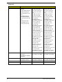
Revision History
Please refer to the table below for the updates made on this service guide.
Date Version Chapter Updates
08-17-2012 First Draft
08-22-2012 V1.00

iii
Copyright
Copyright © 2012 by Acer Incorporated. All rights reserved. No part of this publication may be reproduced,
transmitted, transcribed, stored in a retrieval system, or translated into any language or computer language, in
any form or by any means, electronic, mechanical, magnetic, optical, chemical, manual or otherwise, without
the prior written permission of Acer Incorporated.

iv
Disclaimer
The information in this guide is subject to change without notice.
Acer Incorporated makes no representations or warranties, either expressed or implied, with respect to the
contents hereof and specifically disclaims any warranties of merchantability or fitness for any particular
purpose. Any Acer Incorporated software described in this manual is sold or licensed "as is". Should the
programs prove defective following their purchase, the buyer (and not Acer Incorporated, its distributor, or its
dealer) assumes the entire cost of all necessary servicing, repair, and any incidental or consequential
damages resulting from any defect in the software.
Acer is a registered trademark of Acer Corporation.
Other brand and product names are trademarks and/or registered trademarks of their respective holders.
HDMI, the HDMI logo, and High Definition Multimedia Interface are trademarks or registered trademarks of
HDMI Licensing, LLC in the United States and other countries.

v
Conventions
The following conventions are used in this manual:
SCREEN
MESSAGES
Denotes actual messages that appear on screen.
NOTE Gives additional information related to the current topic.
WARNING Alerts you to any physical risk or system damage that might result from doing
or not doing specific actions.
CAUTION Gives precautionary measures to avoid possible hardware or software
problems.
IMPORTANT Reminds you to do specific actions relevant to the accomplishment of
procedures.

vi
Service Guide Coverage
This Service Guide provides you with all technical information relating to the BASIC CONFIGURATION
decided for Acer's "global" product offering. To better fit local market requirements and enhance product
competitiveness, your regional office MAY have decided to extend the functionality of a machine (e.g. add-on
card, modem, or extra memory capability). These LOCALIZED FEATURES will NOT be covered in this generic
service guide. In such cases, please contact your regional offices or the responsible personnel/channel to
provide you with further technical details.
FRU Information
Please note WHEN ORDERING FRU PARTS, that you should check the most up-to-date information available
on your regional web or channel. If, for whatever reason, a part number change is made, it will not be noted in
the printed Service Guide. For ACER-AUTHORIZED SERVICE PROVIDERS, your Acer office may have a
DIFFERENT part number code to those given in the FRU list of this printed Service Guide. You MUST use the
list provided by your regional Acer office to order FRU parts for repair and service of customer machines.

vii
Features and Specifications...............................................................................1
System Features . . . . . . . . . . . . . . . . . . . . . . . . . . . . . . . . . . . . . . . . . . . . . . . . . . . . . .1
Audio . . . . . . . . . . . . . . . . . . . . . . . . . . . . . . . . . . . . . . . . . . . . . . . . . . . . . . . . . . . . . .
.2
I/O Ports and LED Indicators. . . . . . . . . . . . . . . . . . . . . . . . . . . . . . . . . . . . . . . . . . . . .2
Physical Specifications . . . . . . . . . . . . . . . . . . . . . . . . . . . . . . . . . . . . . . . . . . . . . . . . .3
Environmental Requirements . . . . . . . . . . . . . . . .
. . . . . . . . . . . . . . . . . . . . . . . . . . . .3
System Tour . . . . . . . . . . . . . . . . . . . . . . . . . . . . . . . . . . . . . . . . . . . . . . . . . . . . . . . . .4
Front View . . . . . . . . . . . . . . . . . . . . . . . . . . . . . . . . . . . . . . . . . . . . . . . . . . . .4
Rear Panel . . . . . . . . . . . . . . . . . . . . . . . . . . . . . . . . . . . . . . . . . . . . . . . . . . . . . .5
System Utilities....................................................................................................7
CMOS Setup Utility . . . . . . . . . . . . . . . . . . . . . . . . . . . . . . . . . . . . . . . . . . . . . . . . . . . .7
Accessing the Setup Utility . . . . . . . . . . . . . . . . . . . . . . . . . . . . . . . . . . . . . . . . . .8
Navigating through the Setup Utility. . . . . . . . . . . . . . . . . . . . . . . . . . . . . . . . . . . .9
Setup Utility Menus . . . . . . . . . . . . . . . . . . . . . . . . . . . . . . . . . . . . . . . . . . . . . . . . . . .10
Main menu. . . . . . . . . . . . . . . . . . . . . . . . . . . . . . . . . . . . . . . . . . . . . . . . . . . . . .10
Advanced menu. . . . . . . . . . . . . . . . . . . . . . . . . . . . . . . . . . . . . . . . . . . . . . . . . .11
Power menu. . . . . . . . . . . . . . . . . . . . . . . . . . . . . . . . . . . . . . . . . . . . . . . . . . . . .17
Authentication menu . . . . . . . . . . . . . . . . . . . . . . . . . . . . . . . . . . . . . . . . . . . . . .18
Security menu . . . . . . . . . . . . . . . . . . . . . . . . . . . . . . . . . . . . . . . . . . . . . . . . . . .19
Boot Options menu . . . . . . . . . . . . . . . . . . . . . . . . . . . . . . . . . . . . . . . . . . . . . . .21
Exit menu . . . . . . . . . . . . . . . . . . . . . . . . . . . . . . . . . . . . . . . . . . . . . . . . . . . . . .22
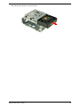
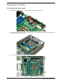
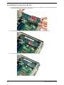
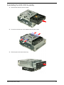
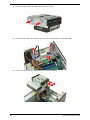
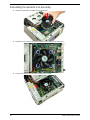
System Disassembly.........................................................................................25
Disassembly Requirements. . . . . . . . . . . . . . . . . . . . . . . . . . . . . . . . . . . . . . . . . . . . .25
Pre-disassembly Procedure . . . . . . . . . . . . . . . . . . . . . . . . . . . . . . . . . . . . . . . . . . . .25
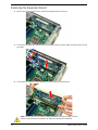
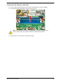
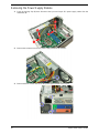
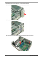
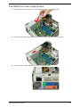
Disassembly Procedures. . . . . . . . . . . . . . . . . . . . . . . . . . . . . . . . . . . . . . . . . . . . . . .26
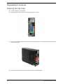
Removing the Side Panel . . . . . . . . . . . . . . . . . . . . . . . . . . . . . . . . . . . . . . . . . .26
Removing the Front Bezel . . . . . . . . . . . . . . . . . .
. . . . . . . . . . . . . . . . . . . . . . . .27
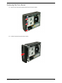
Removing the Heatsink Fan Assembly .
. . . . . . . . . . . . . . . . . . . . . . . . . . . . . . .28
Removing the Processor . . . . . . . . . . . . . . . . . . .
. . . . . . . . . . . . . . . . . . . . . . . .29
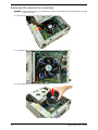
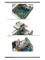
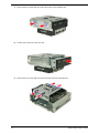
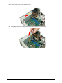
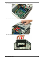
Removing the HDD-ODD Assembly . . . . . . . . . . . . . . . . . . . . . . . . . . . . . . . . . .30
Removing the Expansion Board . . . . . . . . . . . . .
. . . . . . . . . . . . . . . . . . . . . . . .34
Removing the Memory Modules . . . . . . . . . . . . .
. . . . . . . . . . . . . . . . . . . . . . . .35
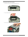
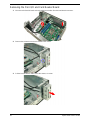
Removing the Power Supply Module. . . . . . . . . . . . . . . . . . . . . . . . . . . . . . . . . .36
Removing the Front I/O and Card Reader Board . . . . . . . . . . . . . . . . . . . . . . . .38
Removing the Power Switch/LED module
. . . . . . . . . . . . . . . . . . . . . . . . . . . . .39
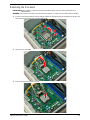
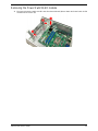
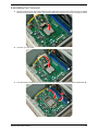
Removing the Mainboard . . . . . . . . . . . . . . . . . . . . . . . . . . . . . . . . . . . . . . . . . .40
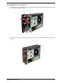
Reassembly Procedures . . . . . . . . . . . . . . . . . . . . . . . . . . . . . . . . . . . . . . . . . . . . . . .42
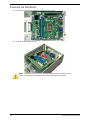
Reinstalling the Mainboard . . . . . . . . . . . . . . . . . . . . . . . . . . . . . . . . . . . . . . . . .42
Reinstalling the Power Switch/LED module . . . . .
. . . . . . . . . . . . . . . . . . . . . . .43
Reinstalling the Front I/O and Card Reader Board . .
. . . . . . . . . . . . . . . . . . . . .44
Reinstalling the Power Supply Module . . . . . . . . . . . . . . . . . . . . . . . . . . . . . . . .45
Reinstalling the Memory Modules . . . . . . . . . . . . . . . . . . . . . . . . . . . . . . . . . . . .47
Reinstalling the Expansion Board . . . . . . . . . . . . . . . . . . . . . . . . . . . . . . . . . . . .48
Reinstalling the HDD-ODD Assembly . . . . . . . . . . . . . . . . . . . . . . . . . . . . . . . . .49
Reinstalling the Processor . . . . . . . . . . . . . . . . . . . . . . . . . . . . . . . . . . . . . . . . . .53
Reinstalling the Heatsink Fan Assembly . . . . . . .
. . . . . . . . . . . . . . . . . . . . . . . .54
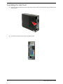
Reinstalling the Front Bezel. . . . . . . . . . . . . . . . . . . . . . . . . . . . . . . . . . . . . . . . .55
Reinstalling the Side Panel . . . . . . . . . . . . . . . . . . . . . . . . . . . . . . . . . . . . . . . . .56
Table of Contents

viii
Troubleshooting................................................................................................57
Hardware Diagnostic Procedure . . . . . . . . . . . . . . . . . . . . . . . . . . . . . . . . . . . . . . . . .57
System Check Procedures . . . . . . . . . . . . . . . . . . . . . . . . . . . . . . . . . . . . . . . . .57
Checkpoints . . . . . . . . . . . . . . . . . . . . . . . . . . . . . . . . . . . . . . . . . . . . . . . . . . . . .58
POST Error Indicators . . . . . . . . . . . . . . . . . . . . . . . . . . . . . . . . . . . . . . . . . . . . .62
Configuring the ME Firmware . . . . . . . . . . . . . . . . . . . . . . . . . . . . . . . . . . . . . . . . . . .73
Clearing CMOS . . . . . . . . . . . . . . . . . . . . . . . . . . . . . . . . . . . . . . . . . . . . . . . . . . . . . .74
BIOS Recovery . . . . . . . . . . . . . . . . . . . . . . . . . . . . . . . . . . . . . . . . . . . . . . . . . . . . . .75
BIOS Update . . . . . . . . . . . . . . . . . . . . . . . . . . . . . . . . . . . . . . . . . . . . . . . . . . . . . . . .76
Updating the BIOS in DOS Mode . . . . . . . . . . . .
. . . . . . . . . . . . . . . . . . . . . . . .76
Updating the BIOS in Windows Mode . . . . . . . . . . . . . . . . . . . . . . . . . . . . . . . . .77
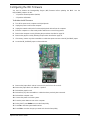
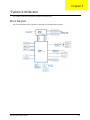
System Architecture..........................................................................................81
Block Diagram . . . . . . . . . . . . . . . . . . . . . . . . . . . . . . . . . . . . . . . . . . . . . . . . . . . . . . .81
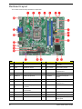
Mainboard Layout . . . . . . . . . . . . . . . . . . . . . . . . . . . . . . . . . . . . . . . . . . . . . . . . . . . .82
Jumper Setting. . . . . . . . . . . . . . . . . . . . . . . . . . . . . . . . . . . . . . . . . . . . . . . . . . .83
Field Replaceable Unit (FRU) List....................................................................85
Exploded Diagram . . . . . . . . . . . . . . . . . . . . . . . . . . . . . . . . . . . . . . . . . . . . . . . . . .86
Aspire XC600 FRU List . . . . . . . . . . . . . . . . . . . . . . . . . . . . . . . . . . . . . . . . . . . . . . . .87
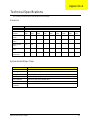
Technical Specifications...................................................................................91
Table of Contents

Aspire XC600 Service Guide 1
This chapter lists the features and specifications of the Aspire XC600 computer.
System Features
NOTE The items listed in this section are for reference only. The exact configuration of your PC depends
on the model purchased. Refer to the FRU list chapter on page 85 for a detailed list of models
supported by each hardware component.
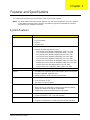
Component Description
Operating system support • Microsoft Windows 8 ML (X64)
• Linpus Xwindows
• FreeDos
• Neokylin Linux
Processor • One LGA 1155 socket
• Supports the following Intel processors:
– Core i5-3330 (3.0G 6M DDR3 1600/1333), Quad Core, 77W
– Core i5-2320 (3.0G 6M DDR3 1333/1066), Quad Core, 95W
– Core i3-3220 (3.3G 3M DDR3 1600/1333), Dual Core, 55W
– Core i3-2130 (3.4G 3M DDR3 1333/1066), Dual Core, 65W
– Core i3-2100 (3.1G 3M DDR3 1333/1066), Dual Core, 65W
– Pentium Dual Core G645 (2.9G 3M DDR3 1066), Dual Core, 65W
– Pentium Dual Core G640 (2.8G 3M DDR3 1066), Dual Core, 65W
– Celeron G550 (2.6G 2M DDR3 1066), Dual Core, 65W
– Celeron G465 (1.9G 1.5M DDR3 1066), Single Core, 35W
Chipset Intel H61 Express Chipset (BD82H61 PCH)
Memory • Two DIMM slots supporting dual-channel DDR3 memory architecture
• Data rate supported: 1066/1333 MT/s
• Maximum memory: 8 GB (using two 4 GB modules)
Expansion options • One PCI Express x16 slot (reserved for GPU card installation)
• One PCI Express x1 slot
• Two SATA 3.0 Gb/s connectors
Connectivity • Wired LAN: Intel 82579V Gbe LAN controller PHY
• WLAN option: Low-profile PCI-E x1 802.11 b/g/n wireless network
adapter and Wireless 802.11b/g/n USB Adapter
• Modem option: 56K Low Profile Dial-Up PCI-E Modem
Hard disk drive (HDD) • One HDD bay suppporting 3.5-inch 25.4 mm SATA HDDs
• Support SATA HDD in 160 – 1500 GB capacities
Optical disc drive (ODD) • One ODD bay supporting 5.25-inch standard SATA ODD
• Supports DVD-R/RW drive or DVD-Super Multi double-layer drive
Features and Specifications
Chapter 1

2 Aspire XC600 Service Guide
Audio
I/O Ports and LED Indicators
Card reader • Multi-in-1 card reader
• The following memory cards are supported:
– CompactFlash (CF) Types I and II
– Memory Stick (MS)
– xD-Picture Card (xD)
– Secure Digital (SD)
– MultiMediaCard (MMC)
– Reduced-Size MultiMediaCard (RS-MMC)
– Memory Stick PRO (MS PRO)
– Microdrive
Power supply • 100~127/200~240 Vac, 220 W non-power factor correction (non-
PFC) power supply unit
• 200~240 Vac, 220 W power factor correction (PFC) power supply unit
Antivirus software Symantec NTI 2009
System BIOS • AMI BIOS with 8 MB SPI Flash ROM
• Supports ACPI and DMI
• Supports Plug and Play, S1/STR(S3)/STD(S4), hardware monitor
Power management • ACPI 2.0 or 1.0b (Advanced Configuration Power Interface) standard
• S0, S1, S2 and S5 sleep states support
• On-board device power management support
• On-board device configuration support
Item Description
Audio codec Realtek ALC662 6-Ch High Definition Audio Codec
Audio jacks • Front panel: Headphone and microphone jacks
• Rear panel: Microphone, line-out, and line-in jacks
Component Description
I/O ports • Front panel
– USB ports (two)
– Headphone jack
– Microphone jack
– Multi-in-1 card reader slots
• Rear panel
– PS/2 keyboard port
– PS/2 mouse port port
– External display (VGA) port
– HDMI port
– USB 2.0 ports (four)
– USB 3.0 ports (two)
– Ethernet jack (RJ45)
– Microphone, line-out, and line-in jacks
Component Description

Aspire XC600 Service Guide 3
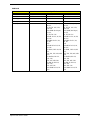
Physical Specifications
Environmental Requirements
LED display and buttons • Power LED
• Power button
Aspect Description
Chassis dimension (W × D × H) 100 mm (W) x 367 mm (D) x 269.5 mm (H)
System weight 5.808 Kg.
Mainboard form factor microATX (µATX)
Mainboard dimensions (W × H) 200mm*244mm , 4 Layers
Aspect Description
Operating temperature 5 to 35 °C (41 to 95 °F)
Operating humidity 15% to 80% RH non-condensing
Component Description

4 Aspire XC600 Service Guide
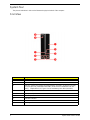
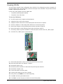
System Tour
The pictures and tables in this section illustrate the physical outlook of the computer.
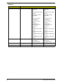
Front View
No. Component
1 Optical drive cover
2 Optical drive eject button
3 Multi-in-1 optional card reader supporting Memory Stick (MS), xD-Picture Card (xD),
Secure Digital (SD), MultiMediaCard (MMC), Reduced-Size MultiMediaCard (RS-
MMC), CompactFlash (CF) Types I and II, and Memory Stick PRO (MS PRO)
4 Headphone jack
5 Microphone-in jack
6 USB 2.0 ports
7 ODD LED indicator
8 Power button/indicator
9Acer logo

Aspire XC600 Service Guide 5
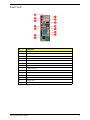
Rear Panel
No. Component
1 PCI Expansion slot
2 Microphone jack
3 USB 2.0 ports
4 USB 3.0 ports
5 HDMI port
6 PS/2 mouse connector
7 PS/2 keyboard connector
8 Power connector
9 Kensington lock
10 External monitor port
11 LAN connector
12 Line-in jack
13 Line-out jack
14 HDMI port

6 Aspire XC600 Service Guide

Aspire XC600 Service Guide 7
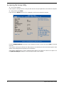
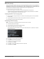
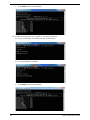
CMOS Setup Utility
CMOS Setup Utility is a hardware configuration program built into the system ROM. Since most systems are
already properly configured and optimized, there is normally no need to run this utility.
You will need to run this utility under the following conditions:
• When changing the system configuration including:
• Setting the system time and date
• Configuring the system drives and peripherals
• Specifying the boot device sequence
• Configuring the power management modes
• Setting up system passwords or making other changes to the security setup
• When trying to resolve IRQ conflicts
• When a configuration error is detected by the system and you are prompted ("Run Setup" message) to
make changes to the BIOS settings.
The Setup Utility loads the configuration values in a battery-backed nonvolatile memory called CMOS RAM.
This memory area is not part of the system RAM, which allows configuration data to be retained when power is
turned off. The values take effect when the system is booted. POST uses these values to configure the
hardware. If the values and the actual hardware do not agree, POST generates an error message. You must
run this utility to change the hardware settings from the default or current configuration.
IMPORTANT If you repeatedly receive “Run Setup” messages, the RTC battery located on the mainboard
(BT1) may be defective. In this case, the system cannot retain configuration values in CMOS.
Replace the RTC battery with a new one.
NOTE For ease of reading, CMOS Setup Utility will be simply referred to as “Setup” or “Setup Utility” in this
Service Guide.
System Utilities
Chapter 2

8 Aspire XC600 Service Guide
Accessing the Setup Utility
1. Turn on the computer.
If the computer is already turned on, save your data and close all open applications, then restart the computer.
2. During POST, press Delete.
If you fail to press Delete before POST is completed, you will need to restart the computer.
Use the Left/Right/Up/Down arrow keys to move between the menu screens, then press Enter to view that
menu tab.
Some options lead to pop-up dialog boxes that prompt you to verify that you wish to execute that option. Other
options lead to dialog boxes that prompt you for information.
Some options (marked with a ) lead to submenus that enable you to change the values for the option. Use
the Up/Down/Left/Right arrow keys to scroll through the items in the submenu

Aspire XC600 Service Guide 9
Navigating through the Setup Utility
Use the keys listed in the legend bar on the bottom of the Setup screen to work your way through the various
menu and submenu screens of the Setup Utility. The table below lists these legend keys and their respective
functions.
Key Function
Left/Right arrow
keys
Move the cursor to the menu screen you want. The currently selected screen will be
highlighted and the items it contain will be shown.
Up/Down arrow
keys
Move the cursor to the item you want. The currently selected field will be highlighted.
Enter • To open the page for the currently selected menu/submenu
• To apply a field value.
+ / - / space bar To select a value for the currently selected field (only if it is user-configurable). Press
these keys repeatedly to display all possible entries. A parameter that is enclosed in
square brackets [ ] is user-configurable. Black font parameters are not user-
configurable for one of the following reasons:
• The field value is auto-configured or auto-detected.·
• The field value is informational only.
• The field is password-protected.
F1 To bring up the General Help
window. The General Help window describes other Setup
navigation keys that are not displayed on the legend bar.
F7 Restore the saved User Default settings.
F8 Save the current menu settings as User Default settings.
F9 Press to load default system values.
F10 Press to save changes and close the Setup Utility.
Esc If you press this key:
• On one of the primary menu screens, the Exit
menu displays.
• On a submenu screen, the previous screen displays.
• When you are making selections from a pop-up menu, closes the pop-up without
making a selection.

10 Aspire XC600 Service Guide
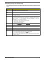
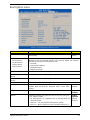
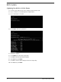
Setup Utility Menus
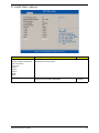
The Setup Utility has seven menus for configuring the various system functions. These include:
Main menu
Main Advanced Power Authentication Security Boot Options Exit
NOTES • The screenshots used in this section are for illustration only. The values displayed may not be
the same as those in your computer.
• In the descriptive tables following each of the menu screen illustrations, settings in boldface are
the default and suggested settings.
Field Description
System BIOS
Version Current system BIOS version
Build Date Date when the system BIOS was built.
Processor
<model> Processor model installed
Core Frequency Core frequency of the installed processor
Count Multi-core factor of the installed processor (number of processor cores)
Memory
Size Size of system memory detected during boot-up
Product Name Official model name of the computer.
System Serial Number System serial number.
Asset Tag Number System asset tag number
System Date Sets the system date.
System Time Sets the system time.

Aspire XC600 Service Guide 11
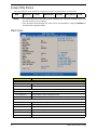
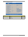
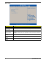
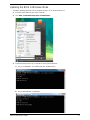
Advanced menu
Field Description
Miscellaneous Access this submenu to view the properties of installed SATA devices and
configure miscellaneous system settings.
Advanced Chipset
Configuration
Access this submenu to enable or disable various Intel technology functions
and configure video memory settings.
Integrated Peripherals Access this submenu to enable or disable operation modes for the onboard
I/O controllers.
PC Health Status Access this submenu to view current level of system/processor/PCH
temperature, voltages, and fan speed.
Smart Fan Configuration Access this submenu to view current smart fan configuration setting.

12 Aspire XC600 Service Guide
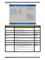
Miscellaneous submenu
Field Description Value
AHCI Port 0-2 Your computer supports three SATA channels, each channel allows one SATA device to
be installed. Press Enter to display the individual configuration screen of installed SATA
drive(s).
Spread Spectrum Enable or Disable mainboard spread spectrum clocking. Enabled
Disabled
Processor
Multiplier
Displays the current system processor multiplier value.
Bootup Num-
Lock
If you set this item to On, the keyboard Num Lock key will be active
when the computer boots up.
On
Off
USB Beep
Message
Select whether to allow the BIOS to emit error beeps or display error
messages during USB device enumeration.
Enabled
Disabled
Page is loading ...
Page is loading ...
Page is loading ...
Page is loading ...
Page is loading ...
Page is loading ...
Page is loading ...
Page is loading ...
Page is loading ...
Page is loading ...
Page is loading ...
Page is loading ...
Page is loading ...
Page is loading ...
Page is loading ...
Page is loading ...
Page is loading ...
Page is loading ...
Page is loading ...
Page is loading ...
Page is loading ...
Page is loading ...
Page is loading ...
Page is loading ...
Page is loading ...
Page is loading ...
Page is loading ...
Page is loading ...
Page is loading ...
Page is loading ...
Page is loading ...
Page is loading ...
Page is loading ...
Page is loading ...
Page is loading ...
Page is loading ...
Page is loading ...
Page is loading ...
Page is loading ...
Page is loading ...
Page is loading ...
Page is loading ...
Page is loading ...
Page is loading ...
Page is loading ...
Page is loading ...
Page is loading ...
Page is loading ...
Page is loading ...
Page is loading ...
Page is loading ...
Page is loading ...
Page is loading ...
Page is loading ...
Page is loading ...
Page is loading ...
Page is loading ...
Page is loading ...
Page is loading ...
Page is loading ...
Page is loading ...
Page is loading ...
Page is loading ...
Page is loading ...
Page is loading ...
Page is loading ...
Page is loading ...
Page is loading ...
Page is loading ...
Page is loading ...
Page is loading ...
Page is loading ...
Page is loading ...
Page is loading ...
Page is loading ...
Page is loading ...
Page is loading ...
Page is loading ...
Page is loading ...
Page is loading ...
Page is loading ...
Page is loading ...
Page is loading ...
Page is loading ...
Page is loading ...
Page is loading ...
Page is loading ...
Page is loading ...
Page is loading ...
Page is loading ...
-
 1
1
-
 2
2
-
 3
3
-
 4
4
-
 5
5
-
 6
6
-
 7
7
-
 8
8
-
 9
9
-
 10
10
-
 11
11
-
 12
12
-
 13
13
-
 14
14
-
 15
15
-
 16
16
-
 17
17
-
 18
18
-
 19
19
-
 20
20
-
 21
21
-
 22
22
-
 23
23
-
 24
24
-
 25
25
-
 26
26
-
 27
27
-
 28
28
-
 29
29
-
 30
30
-
 31
31
-
 32
32
-
 33
33
-
 34
34
-
 35
35
-
 36
36
-
 37
37
-
 38
38
-
 39
39
-
 40
40
-
 41
41
-
 42
42
-
 43
43
-
 44
44
-
 45
45
-
 46
46
-
 47
47
-
 48
48
-
 49
49
-
 50
50
-
 51
51
-
 52
52
-
 53
53
-
 54
54
-
 55
55
-
 56
56
-
 57
57
-
 58
58
-
 59
59
-
 60
60
-
 61
61
-
 62
62
-
 63
63
-
 64
64
-
 65
65
-
 66
66
-
 67
67
-
 68
68
-
 69
69
-
 70
70
-
 71
71
-
 72
72
-
 73
73
-
 74
74
-
 75
75
-
 76
76
-
 77
77
-
 78
78
-
 79
79
-
 80
80
-
 81
81
-
 82
82
-
 83
83
-
 84
84
-
 85
85
-
 86
86
-
 87
87
-
 88
88
-
 89
89
-
 90
90
-
 91
91
-
 92
92
-
 93
93
-
 94
94
-
 95
95
-
 96
96
-
 97
97
-
 98
98
-
 99
99
-
 100
100
-
 101
101
-
 102
102
-
 103
103
-
 104
104
-
 105
105
-
 106
106
-
 107
107
-
 108
108
-
 109
109
-
 110
110


Acer Aspire XC600 User manual
- Category
- Server/workstation motherboards
- Type
- User manual
Ask a question and I''ll find the answer in the document
Finding information in a document is now easier with AI
