All-Power APGG7500 Owner's manual
- Category
- Power generators
- Type
- Owner's manual

7500WATTGENERATOR
Owner's ManuaJ
Limited Warranty
AIEPower warrants to the original purchaser who uses the product in a consumer
application (personal, residential or household usage) that all products covered under this
7500W Generator
Table of Contents
Topic Page
Limited Warrant_ 3
Safety Guidelines 5
General Precautions 6
Battery 15
Assembly 16
Operation 17
Spark Plug Service 22
Inspection, Cleaning, Maintenance and Storage 23
Installation 29
Compliance 31
Specifications 32
General Parts Listing 33
WARNING! READ AND UNDERSTAND ALL SAFETY PRECAUTIONS
IN THIS MANUAL BEFORE OPERATING. FAILURE TO COMPLY WITH
INSTRUCTIONS IN THIS MANUAL COULD RESULT IN PERSONAL
INJURY, PROPERTY DAMAGE, AND/OR VOIDING OF YOUR
WARRANTY. ALL=POWER WILL NOT BE LIABLE FOR ANY DAMAGE
BECAUSE OF FAILURE TO FOLLOW THESE INSTRUCTIONS.
7500W Generator
Limited Warranty (cont'd)
THIS WARRANTY DOES NOT COVER:
warranty are free from defects in material and workmanship for one year from the date of
purchase. A{I products covered by this limited warranty which are used in commercial applications
(i.e. income producing) are warranted to be free of defects in material and workmanship for
90 days from the date of original purchase. Products covered under this warranty include air
compressors, air tools, service parts, pressure washers and generators.
A{FPower wifl repair or rep{ace, at A{FPower sole option, products or
components which have failed within the warranty period. Service will be schelduled according
to the normal work flow and business hours at the service center location, and the avaifibflity of
replacement parts. All decisions of Al{-Power with regard to this limited warranty shall be
final.
This warranty gives you specific legal rights, and you may also have other rights which vary from
state to state.
RESPONSIBILITY OF ORIGINAL PURCHASER (initial User):
To process a warranty claim on this product, DO NOT return item to the retailer. The product must
be evaluated by an Authorized Warranty Service Center. For the location of the nearest Authorized
Warranty Service Center call 888.896.6881.
Retain original cash register sales receipt as proof of purchase for warranty to work=
Use reasonab{e care in the operation and maintenance of the product as described in the Owner's
Manual(s).
Deriver or ship the product to the Authorized Warranty Service Center. Freight costs, if any must
be paid by the purchaser.
If the purchaser does not receive satisfactory results form the Authorized Warranty Sercive
Center, the purchser should contact Al{-Power.
= Merchandise sold as reconditioned, used as rental equipment, or floor or display models.
Merchandise that has become damaged or inoperative because of ordinary wear, misuse,
cold, heat, rain, excessive humidity, freeze damage, use of improper chemicals, negligence,
accident, failure to operate the product in accordance with the instructions provided in the
Owner's Manual(s) supplied with the product, improper maintenance, the use of accessories or
attachments not recommended by All-Power, or unauthorized repair or alterations.
Repair and transportation costs of merchandise determine not to be defective.
o Costs assoiciated with assembly, required oil, adjustments or other installation and start-up
costs.
• Expendable parts or accessories supplied with the product which ere expected to become
inoperative or unusable after a reasonable period of use.
Merchandise sold by All-Power which has been manufactured by and identified as the
product of another company, such as gasoline engines. The product manufacturer's warranty, if
any, will apply.
ANY INCIDENTAL, INDIRECT OR CONSEQUENTIAL LOSS, DAMAGE, OR EXPENSE THAT
MAY RESULT FROM ANY DEFECTS, FAILURE OR MALFUNCTION OF THE PRODUCT iS
NOT COVERED BY THIS WARRANTY. Some states do not allow the exclusion, so it may not
apply to you.
IMPLIED WARRANTIES, INCLUDING THOSE OF MERCHANTABILITY OR FITNESS FOR
A PARTICULAR PURPOSE, ARE LIMITED TO ONE YEAR FROM THE DATE OF ORIGINAL
PURCHASE, Some states do not allow limitations on how long an implied warranty lasts, so the
above limitations may not apply to you,

Owner's Manual
Safety Guidelines = Definitions
This manual contains important information that you need to know and
understand in order to protect YOUR SAFETY and to PREVENT
EQUIPMENT PROBLEMS. The following symbols help you recognize this
information. Please read the manual and pay attention to these sections.
Save These important Safety instructions! @
Read and understand all of these safety instructions. Be
sure to retain them for future use.
_ ARNING! WARNINGS INDICATE A CERTAINTY OR STRONG
POSSIBILITY OF PERSONAL INJURY OR DEATH IF
INSTRUCTIONS ARE NOT FOLLOWED.
A CAUTION: CAUTIONS INDICATE A POSSIBILITY OF
EQUIPMENT DAMAGE IF INSTRUCTIONS ARE NOT
FOLLOWED.
_ NOTE: NOTES GIVE HELPFUL INFORMATION
_ ARNING! IMPROPER OPERATION OR MAINTENANCE
OF THIS PRODUCT COULD RESULT IN SERIOUS INJURY
AND PROPERTY DAMAGE. READ AND UNDERSTAND ALL
WARNINGS AND OPERATING INSTRUCTIONS BEFORE USING
THIS EQUIPMENT. WHEN USING AiR TOOLS, BASIC SAFETY
PRECAUTIONS SHOULD ALWAYS BE FOLLOWED TO REDUCE
THE RISK OF PERSONAL INJURY.
Owner's Manual
Fuel or oil spills must be cleaned up immediately. Dispose of fluids and cleaning materials as per
any local, state, or federal codes and regulations. Store oily rags in a covered metal container.
Never store fuel or other flammable materials near the generator.
General Precautions (cont'd)
Gasoline and Oil (cont'd)
Do not smoke, or allow sparks, flames or other sources of ignition around the engine and fuel
tank, Fuel vapors are explosive.
Keep grounded conductive obiects, such as tools, away from exposed, live electrical parts and
connections to avoid sparking or arcing. These events could ignite fumes or vapors.
• Do not refill the fuel tank while the engine is running or while the engine is still hot. Do not
7500W Generator
General Precautions
WARNING! FAILURE TO FOLLOW THESE INSTRUCTIONS CAN RESULT IN
SEVERE INJURY OR DEATH,
_ AUTION: FAILURE TO FOLLOW THESE INSTRUCTIONS CAN ALSORESULT IN DAMAGE TO THE TOOL AND/OR THE ITEM YOU ARE WORKING
ON.
_DANGER @
CARBON MONOXIDE
Using a generator indoors WILL KILL YOU IN MINUTES.
Generator exhaust contains high levels of carbon monoxide (CO), a poisonous gas you cannot
see or smell If you can smell the generator exhaust, you are breathing CO. But even If you
cannot smell the exhaust, you could be breathing CO.
-NEVER use a generator inside homes, garages, crawlspaces, or other partly enclosed areas.
Deadly levels of carbon monoxide can build up in these areas. Using a fan or opening windows
and doors does NOT supply enough fresh air.
-ONLY use a generator outdoors and far away from open windows, doors, and vents. These
openings can pull in generator exhaust.
Even when you use a generator correctly, CO may leak into the home. ALWAYS use a battery-
powered or battery-backup CO alarm in the home.
If you start to feel sick, dizzy, or weak after the generator has been running, move to fresh air
RIGHT AWAY. See a docto_ You could have carbon monoxide poisoning,
WARNING! THE EXHAUST CONTAINS POISONOUS CARBON MONOXIDE
GAS THAT CAN CAUSE LOSS OF CONSCIOUSNESS AND MAY LEAD TO
DEATH,
Gasoline and Oil (_
This product requires oil and fuel. Attempting to start the engine without oil will ruin
the engine and void the warranty. Work in welt ventilated area. Keep cigarettes,
flames or sparks away from the work area or where gasoline is stored.
_ ARNING! GASOLINE IS EXTREMELY FLAMMABLE AND iS EXPLOSIVE
UNDER CERTAIN CONDITIONS, KEEP OUT OF REACH OF CHILDREN,
Gasoline fuel and fumes are flammable and potentially explosive. Use proper fuel storage and
handling procedures, Always have multiple ABD class fire extinguishers nearby,
Keep the generator and surrounding area clean at all times.
7500W Generator
General Precautions (cont'd)
Work Area
Keep your work area clean and well lit, Cluttered benches and dark areas invite accidents.
Do not operate power tools in explosive atmospheres, such as in the presence of flammable
liquids, gases, or dust. Generators create sparks which may ignite the dust or fumes.
Keep bystanders, children, and visitors away while operating a generator. Provide barriers or
shields as needed.
Electrical Safety
operate the generator with known leaks in the fuel system
Excessive buildup of unburned fuel gases in the exhaust system can create a potentially
explosive condition. This buildup can occur after repeated failed start attempts, valve testing, or
hot engine shutdown. If this occurs, open exhaust system drain plugs, if equipped, and allow the
gases to dissipate before attempting to restart the generator.
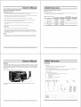
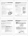
Use only engine manufacturer recommended fuel and oil
Fuel: Oil:
Fuel capacity is 6.6 gallons(25 L). Use regular Oil capacity is 1.16 qt(1.1 L)
unleaded gasoline with a minium octane rating of 90. _
"L"
Hot Components ...... _o0._.,_00.......
WARNING! ENGINE AND EXHAUST SYSTEM PARTS BECOME VERY
HOT AND REMAIN HOT FOR SOME TIME AFTER THE ENGINE IS RUN. WEAR
INSULATED GLOVES OR WAIT UNTIL THE ENGINE AND EXHAUST SYSTEM
HAVE COOLED BEFORE HANDLING THESE PARTS,
Power Output
This generator is not designed to power sensitive electronic equipment (including computers
and medical devices) without the addition of an approved line conditioner, which is sold separately.
CAUTION: ATTEMPTING TO POWER SENSITIVE ELECTRONIC EQUIPMENT
WITHOUT THE USE OF AN APPROVED LINE CONDITIONER MAY CAUSE
DAMAGE TO THE EQUIPMENT. ALL-POWER IS NOT RESPONSIBLE
FOR ANY DIRECT OR INDIRECT DAMAGE CAUSED BY FAILURE TO USE AN
APPROVED LINE CONDITIONER,
Grounded tools must be plugged into an outlet properly installed and
grounded in accordance with all codes and ordinances. Never remove the
grounding prong or modify the plug in any way. Do not use any adapter
plugs.
Grounding provides a low-resistance path to carry electricity away from the
user in the event of an electrical malfunction.
@
Double insulated tools are equipped with a polarized plug where one blade is wider than the
other. This plug fits in a polarized outlet only one way. If the plug does not fit fully in the outlet,
reverse the plug. If it still does not fit, contact a qualified electrician to install a polarized outlet.
Do not change the plug in any way. Double insulation eliminates the need for the three-wire
grounded power cord and grounded power supply system.
Avoid body contact with grounded surfaces such as pipes, radiators, ranges, and refrigerators.
There is an increased risk of electric shock if your body is grounded.
Do not expose generator to rain or wet conditions. Water entering a generator will increase the
risk of electric shock.
Do not abuse the power cord. Keep power cords away from heat, oil, sharp edges, or moving
parts. Replace damaged power cords immediately. Damaged power cords increase the risk of
electdc shock.
When operating a power tool outside, use an outdoor extension cord marked "W-A" or "W".
These extension cords are rated for outdoor use, and reduce the risk of electric shock.

Owner's Manual
General Precautions (cont'd)
Electrical Safety (cont'd)
• All connections and conduits from the generator to the load must on ly be installed by trained and
licensed e{ectricians, and in compliance with all relevant local, state, and federa{ electrica{
codes and standards, and other regulations where applicable.
The generator must be earth-grounded for fixed installations in accordance with all relevant
electrical codes and standards before operation.
Do not attempt to connect or disconnect load connections while standing in water, or on wet or
soggy ground.
Do not touch electrically energized parts of the generator and interconnecting cables or
conductors with any part of the body, or with any nominsulated conductive obiect.
Connect the generator only to a load or electrical system (120 volt) that is compatible with the
electrical characteristics and rated capacities of the generator.
Before servicing equipment powered by the generator, disconnect the equipment from its power
input.
Keep all electrical equipment clean and dry. Replace any wiring where the insulation is cracked,
cut abraded or otherwise degraded. Replace terminals that are worn, discolored, or corroded.
Keep terminals clean and tight.
Insulate all connections and disconnected wires.
Guard against electric shock. Prevent body contact with grounded surfaces such as pipes,
radiators, ranges, and refrigerator enclosures.
Personal Safety
Stay alert. Watch what you are doing, and use common sense when operating a generator. Do
not use generator while tired or under the influence of drugs, alcohol, or medication. A moment
of inattention while operating generators may result in serious personal injury.
Dress properly. Do not wear loose clothing or jewelry. Contain long hair. Keep your hair, clothing,
and gloves away from moving parts. Loose clothes, iewelry, or long hair can be caught in
moving parts.
Owner's Manual
General Precautions (cont'd)
Servicing
Maintain labels and name plates on the generator and engine. These carry important information.
If unreadable or missing, contact our service center toll free at 888-896-6881 immediately for a
replacement.
Generator service must be performed only qualified repair personnel. Service or maintenance
performed by unqualified personnel could result in a risk of injury.
When servicing a generator, use only identical replacement parts. Follow all appropriate
instructions in this manual. Use of unauthorized parts or failure to foflow maintenance instructions
may create a risk of electric shock or injury.
Heart Pacemakers
WARNI NG! PEOPLE WITH PACEMAKERS SHOULD CONSULT THEIR
PHYSiCIAN(S) BEFORE USING THIS PRODUCT. ELECTROMAGNETIC
FIELDS IN CLOSE PROXIMITY TO A HEART PACEMAKER COULD CAUSE
INTERFERENCE TO OR FAILURE OF THE PACEMAKER.
installation
Ensure instaEtation meets all applicabte safety, and IocaE and national electrical codes. Have
installation performed by a qualified, licensed electrician and building contractor.
All electrical work, including the earth-ground connection, should be completed by a licensed
electrician.
Any separate fuel storage or generator supply facility must be built or installed in full compliance
with all relevant local, state, and federal regulations.
7500W Generator
General Precautions (cont'd)
Personal Safety (cont'd)
Avoid accidental starting, Make sure the power switch is in its "OFF" position, and disconnect
the spark plug wire when not in use.
Remove adjusting keys or wrenches before turning the generator on. A wrench or a key that is
left attached to a rotating part of the generator may result in personal iniury.
Do not overreach. Keep proper footing and balance at all times.
Use safety equipment. Always wear eye protection. Wear ANSI approved safety impact eye
goggles. Dust mask, non-skid safety shoes, hard hat, or hearing protection must be used for
appropriate conditions.
Do not force the generator. Use the correct generator for your application. The correct generator
will do the job better and safer at the rate for which it is designed.
Do not use the generator if the power switch does not turn it on or off. Any generator that cannot
be controlled with the power switch is dangerous and must be replaced.
Generator Use and Care
Make sure the power switch is in its "OFF" position and disconnect the spark plug wire before
making any adjustment, changing accessories, or storing the generator. Such preventive safety
measures reduce the risk of starting the generator accidentally.
Store idle generators out of reach of children and other untrained persons. Generators are
dangerous in the hands of untrained users.
Maintain generators with care. Do not use damaged generator. Tag damaged generators "Do not
use" until repaired.
Check for misalignment or binding of moving parts, breakage of parts, and any other condition that
may affect the generator's operation. If damaged, have the generator serviced before using. Many
accidents are caused by poorly maintained generators.
Use only accessories that are recommended by the manufacturer for your model Accessories that
may be suitable for one generator may become hazardous when used on another generator.
7500W Generator
General Precautions (cont'd)
Installation (cont'd)
If the generator is installed outdoors, it must be weatherproofed and should be soundproofed. It
should not be run outdoors without protection to the generator and wiring conduit.
The generator weighs 1001bs (approx). Two or more people should assist when moving or lifting
this product. Never lift the generator using the engine or alternator lifting lugs. Connect lifting
equipment to the frame of the generator
Before rifting the generator, ensure the lift rigging and supporting structure are in good
condition, and are rated to lift such a load.
Keep all personnel away from the suspended generator during relocating.
The supporting floor/ground surface should be level and strong enough to safely hold the weight
of the generator. If the floor/grounded surface is not level, strong cross members should be
placed under the full length of the generator frame at its low side.
For trailer in stallation, the generator should be mounted on the center point of the trailer, over
the wheels. The trailer must be capable of supporting the weight of the generator and all
contents (tools, etc.)
Install sound-and weather-proofing only when it is not raining or snowing to avoid trapping
moisture within the generator's area.
Mechanical
Always make sure the power switch is in its "OFF" position. Disconnect the spark plug wire, and
allow the engine to completely cool before carrying out maintenance.
Check for damaged parts. Before using the generator, any part that appears damaged should
be carefully checked to determine that it will operate properly and perform its intended function.
Check for alignment and binding of moving parts, any broken parts or mounting fixtures, and any
other condition that may affect proper operation technician.
The generator is designed with guards for protection from moving parts. In any case, care must
still be taken to protect personnel and equipment from other mechanical hazards when working
around the generator.

Owner's Manual
General Precautions (cont'd)
Mechanical (cont'd)
• DO not operate the generator wfth safety guards removed, While the generator is running, do not
attempt to reach around the safety guard for maintenance or any other reason,
• Keep hands, arms, long hair, loose clothing, and jewelry away from moving parts. Be aware that
when engine parts are moving fast they cannot be seen clearly.
• Keep access doors on enclosures closed and locked when access is not required.
• When working on or around the generator always wear protective clothing including ANSI
approved safety gloves, safety eye goggles, and safety hat.
• Do not alter or adjust any part of the generator that is assembled and supp{fed by the
manufacturer.
• Always follow and complete scheduled engine and generator maintenance.
Chemicals
• Avoid contact with hot fuel, oil, exhaust fumes, and hot solid surfaces.
• Avoid body contact with fuels, oils, and lubricants used in the generator, If swallowed, seek
medical treatment immediately. Do not induce vomiting ff fuel is swallowed. For skin contact,
immediately wash with soap and water. For eye contact, immediately flush eyes with clean water
and seek medical attention.
Noise
• Prolonged exposure to noise levels above 68 DBA is hazardous to hearing. Always wear ANSI
approved ear protection when operating or working around the generator when it is running.
Owner's Manual
Battery
To start generator with electric start you will need a battery (not included). You can use a 12v lawn
tractor battery with the following specifications: The dimensions are Wx7.5" Dx5" Hx7" (including
terminals). A rated cranking amperage of 200. Terminals are regular, not reversed. Note: Using a
battery not designed for this unit may void warranty. Also this generator can also be started with
the pull start.
Photos below demonstrate battery plate attachment.
Put the battery on the frame, have the battery assembled with the provided accessories
as shown.
7500W Generator
GeneraJ Precautions (cont'd)
Extension Cord
If an extension cord (not included) fs used, make sure to use only UL approved cords having the
correct gauge and length according to the followfng table
NamepJate Amps (@ fag Joad) Cord Lengths
Oft.= 50fto 50fL=lO0fto lOOfto=150ffo 150fto=200fto
0 - 5 16 AWG 16 AWG 12 AWG 12 AWG
5.1 - 8 16AWG 14AWG IOAWG
8.1 - 12 14AWG 12AWG
12.1 - 15 12AWG 10AWG
15 - 20 10AWG 10AWG
Assembly
Unpacking
1. Remove the generator and loose parts box from the carton.
2. Compare the accessory with the inventory list below.
Loose Parts (Wheel kit and handle)
Check all loose parts against the following list. Contact your dealer toll free at 888.896.6881
if any of the loose parts shown are not included with your generator
Hardware Check:
Your Hardware Kit should include:
1) Two Handles with bolts, nuts, pin with chain and brackets
2) One axle shaft with bolts and nuts
3) Two washers
4) Two cotter pins
5) One generator leg with bolts and nuts
6) Two wheels
--1
@@ @@
7500W Generator

Owner's Manual
Operation .........
/
_ OTE: THE PARTS LISTED ABOVE ARE HELPFUL FOR LOCATING THE
CONTROLS MENTIONED BELOW,
7500W Generator
Operation (cont'd)
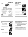
Starting
1, Put the engine switch on the "RUN" position.
The engine switch enables and disables the ignition
system.
STOP: To stop the engine
RUN: To run the engine
START: To Start the engine
2. The fuel valve is located under the fuel tank . When
CAUTION: PRIOR TO FIRST USING THE GENERATOR, THE ENGINE MUST BE
FILLED WiTH OiL OF A HiGH QUALITY SAE 10W-30 GRADE ENGINE OIL,
TO DO SO, UNSCREW AND REMOVE THE ENGINE'S OIL DiPSTiCK LOCATED
AT THE BOTTOM OF THE ENGINE CRANKCASE. FiLL THE ENGINE'S
CRANKCASE UNTIL THE OIL LEVEL IS LEVEL WiTH THE UPPER MARKED
LINE ON THE DIPSTICK, THEN SCREW THE DIPSTICK BACK INTO
THE OIL FILL HOLE.
Before Starting the Generator Fuel tank capacity:25L(6.6gallons)
1. Check that the engine power switch is in its
"OFF" position.
2. Before the first use, remove the fuel
tank cap and fill the fuel tank with unteaded
gasofine. When fuefing, be sure that the
fuel strainer is in place. Replace the fuel
tank cap. Thereafter, check the engine's
fuel gauge for the amount of unleaded
gasoline in the fuel tank. If necessary, FUEL TAf_K CAP
refil} the fuel tank with unleaded gasoline;
the generator must be turned off and
cooled down before refilling the fuel tank,
Use gasoline with a pump octane rating of 90 or higher.
We recommend unleaded gasoling because it produces
fewer engine and spark plug deposits and extends
exhaust system life.
Never use stale or contaminated gasoline or oil/gasoline .....
mixture. Avoid getting dirt or water in the fuel tank.
Owner's Manual
Operation (cont'd)
the valve lever is in the ON position, fuel is allowed
to flow from the fuel tank to the carburetor. Be sure
to return the fuel valve lever to the "OFF" position after
stopping the engine.
3. To start a cold engine, move the choke lever to the
"Start" position. To restart a warm engine, leave the
choke lever in the "RUN" position.
The choke lever opens and closes the choke valve in
the carburetor.
The "Start" position enriches the fuel mixture from
starting a cold engine.
The "RUN" position provides the correct fuel mixture
for operation after starting, and for restarting a warm
engine.
7500W Generator
Starting
4. Operate the Recoil Start:
Puff the starter grip lightly until you feel resistance,
then puff bdsMy. Return the starter grip gently.
Pulling the starter grip operates the recoil start to
crank the engine
Operate the Electric start:
Push and hold the engine switch on the "START"
position for 3-5s and crank the engine.
5. If the choke has been moved to the "Start" position
to start the engine, gradually move it to the "RUN"
position as the engine warms up.
Stopping Engine
1. Turn the engine switch to the "STOP" position.
2. Turn the fuel valve lever to the "OFF" position.
When the engine is not in use, leave the fuel valve in
the "OFF" position to prevent carburetor flooding
and to reduce the possibility of fuel leakage.
Operation (cont'd)
Powering 120 Volt AC Tools And Equipment:
1. Pdor to powering tools and equipment, make sure the generator's rated voltage, and amperage
capacity (120 V AC @ 50 AM Ps) is adequate to supply all electrical {cads that the unit will
power. If powering exceeds the generator's capacity, it may be necessary to group one or more
of the tools and/or equipment for connection to a separate generator.
CAUTION: ATTEMPTING TO POWER SENSITIVE ELECTRONIC EQUIPMENT
_ ITHOUT THE USE OF AN APPROVED LINE CONDITIONER MAY CAUSE
DAMAGE TO THE EQUIPMENT. ALL-POWER IS NOT RESPONSIBLE FOR
ANY DIRECT OR INDIRECT DAMAGE CAUSED BY FAILURE TO USE AN
APPROVED LINE CONDITIONER,
2. Once the generator is running, simply connect the power cords of 120 volt AC powered
tools and equipment into the 120 volt AC dual outlets.
L_ NOTE: THE GENERATOR FEATURES AN AC NON-FUSE THERMAL PROTECTOR
TO PROTECT THE AC CIRCUIT IN CASE OF AN OVERLOAD. SHOULD
AN OVERLOAD OCCUR, THE BREAKER WILL POP,
3. Disconnect all electrical powered tools and equipment from the generator's 120 volt AC
duel outlets.
4. After the engine and generator have completely cooled, store generator in a safe, clean, dry
location (if not already installed).

Owner's Manual
Operation (cont'd)
Powering 12 Volt DC tools and Equipment:
1. Prior to powering tools and equipment, make sure the generator's rated voltage, and amperage
capacity (12VDC) is adequate to supply all electrical loads that the unit will power. If powering
exceeds the generator's capacity, it may be necessary to group one or more of the tools and/or
equipment for connection to a separate generator.
2. Connect the power cord of a 12 VDC powered tool or equipment to the DC Terminals.
_ AUTION: MAKE SURE TO CONNECT THE POSITIVE (+) LEAD OF THE
POWER CORD TO THE POSiTiVE (+) TERMINAL ON THE GENERATOR,
AND CONNECT THE NEGATIVE (-) LEAD OF THE POWER CORD TO THE
NEGATIVE (-) TERMINAL ON THE GENERATOR.
THE 12V DC iS FOR BATTERY CHARGING ONLY.
Owner's Manual
inspection, CJeaning, and
Maintenance
_ WARNING! ALWAYS MAKE SURE THE ENGINE POWER SWITCH (2) IS IN ITS
"OFF" POSITION. DISCONNECT THE SPARK PLUG WIRE FROM THE ENGINE.
AND ALLOW SUFFICIENT TIME FOR THE ENGINE AND GENERATOR TO
COMPLETELY COOL BEFORE PERFORMING ANY INSPECTIONS,
MAINTENANCE, OR CLEANING.
7500W Generator
Spark Plug Service
In order to service the spark plug, you will need a spark plug wrench (commercially available).
Recommended spark plugs: NHSP LD F7TC or NGKBPRGES but we recommend our OEM spark
plug. To ensure proper engine operation, the spark plug must be properly gapped and free of
deposits.
1. Remove the spark plug cap.
2. Clean any dirt from around the spark plug base.
3. Use a spark plug wrench to remove the spark plug.
4. Visually inspect the spark plug. Discard it if the insulator is cracked or chipped. Clean the spark
plug with a wire brush if it is to be reused.
5. Measure the plug gap with a feeler gauge.(Correct as necessary by carefully bending the side electrode.)
The gap should be : 0.70-0.80 mm (0.028-0.031 in)
6. Check that the spark plug washer is in good condition.
7. After the spark plug is seated, tighten with a spark plug in by hand to prevent cross-threading.
8. After the spark plug is seated, tighten with a spark plug wrench to compress the washer.
_ NOTE: THE SPARK PLUG MUST BE SECURELY TIGHTENED. AN IMPROPERLY
TIGHTENED SPARK PLUG CAN BECOME VERY HOT AND COULD DAMAGE THE
ENGINE. NEVER USE SPARK PLUGS WHICH HAVE AN IMPROPER HEAT RANGE.
USE ONLY RECOMMENDED SPARK PLUS OR EQUIVALENT.
7500W Generator
Fuel Sediment Cup Cleaning
The sediment cup prevents dirt or water which may be in the fuel tank from entering the carburetor.
If the engine has not been run for a long time, the sediment cup should be cleaned.
1. Turn the fuel valve to the OFF position. Remove the sedement cup, and O-ring.
2. Clean the sediment cup, and O-ring, in nonflammable or high flash point solvent.
3. Reinstall O-ring, and sediment cup.
4. Turn the fuel valve ON and check for leaks.
I O_R_

Owner's Manual
Maintenance Guide
Periodic maintenance and adjustment is necessary to keep the generator in good operating
condition.
WARNING! Exhaust gas contains poisonous carbon monoxide. Shut off the engine before
performing any maintenance. If the engine must be run, make sure the areas is well ventilated.
Before each use, inspect the generator. Check for:
- Loose screws
- Misaligned or binding moving parts
- Cracked or broken parts
- Damaged electrical wiring
- Any other condition that may affect safe operation.
If an engine problem occurs, have it checked by a qualified service technician before further use.
Do not use damaged equipment.
Before each use, make sure the engine's oil and gas levels are adequate. If necessary, fill the
crankcase until the oil level is even with the oil hill hole and/or fill the fuel tan k.
Before each use, remove all debris with a soft brush, rag, or vacuum.
7500W Generator
Air cleaner service
A dirty air cleaner will restrict air flow to the carburetor. To prevent carburetor malfuncion, service
the air cleaner regularly. Service more frequently when operating the generator in extremely dusty
areas.
A WARNING! Using gasoline or flammable solvent to clean the filter element
can cause a fire or explosion, Use only soapy water or nonflammable
solvent.
NOTE: Never run the without the air cleaner. Rapid engine wear
generator
will result,
1. Unsnap the air cleaner cover clips, remove the air
cleaner cover, and remove the e_ement.
Lubricate all moving parts using a premium
quality, lightweight machine oiL
Every 50 hours of use, drain the old engine oil
and replace with a high a high quality
SAE 10W-30 grade engine oil.
Every 300 hours of use, have a qualified, certified
technician perform thorough maintenance on the
generator and engine.
For long term storage, either drain fuel into
suitable container or add a fuel preservative/
stabilizer (not included) to prevent fuel
breakdown.
Upper Level
Owner's Manual
Transporting/Storage
When transporting the generator, turn the engine switch and the fuel valve OFF, Keep the
generator level to prevent fuel spillage. Fuel vapor or spilled fuel may ingite.
WARNING! Contact with a hot engine or exhaust system can cause
serious burns or fires, Let the engine cool before transporting or
storing the generator.
STORAGE TiME
Less than I month
1 to 2 months
2 months to 1 year
Take care not to drop or strike the generator when transporting. Do not place heavy
objects on the generator.
Before storing the unit for an extended period:
1, Be sure the storage area is free of excessive humidity and dust,
2. Service according to the table below:
RECOMMENDEDSERVICEPROCEDURE
TOPREVENTHARDSTARTING
No preparation required
Fill with fresh gasoline and add gasoline conditioner*,
Fill with fresh gasoline and add gasoline conditioner*,
Drain the carburetor float bowl,
Drain the fuel sediment cup.
1 year or more Fill with fresh gasoline and add gasoline conditioner*,
Drain the carburetor float bowl,
Drain the fuel sediment cup.
2, Wash the element in a solution of household detergent
and warm water, then rinse thoroughly, or wash in
nonflammable or high flash point solvent. Allow the
element to dry thorughly.
3, Soak the element in clean engine oil and squeeze
out the excess oil The engine will smoke during
initial start-up if too much oil is left in the element.
CLiP
4, Reinstall the air cleaner element and the cover,
ELEf_T
At_ CLEANER ELEMEP4T
7500W Generator
Transporting/Storage
2, Char_ge the er_g4r_e oii
3, Remove the spark I_##, a_ pour about a labl÷spoor_ of dear_ engi_ o_i
it_tol_!_e_l_er, Cra_k the engine _etaJ r_¢o_t_o ns to d_tribute the _
the_ reinsta_i the _aA p}_#
4, Stowly pu]] the starter grip uotJl tsa_sta_,_ i8 fe_t, At this pc|hi, the pisl[o_
is comity@ #p on ils compress;ion _roke ar'_J both the intak_ at_d exhau_
Remove the spark plug. Put a tablespoon of engine oil into
the cylinder. Turn the engine slowly with the pull rope to
distribute the oil, Reinstall the spark plug,
Change the engine oil,
After removal from storage, drain the stored gasoline
into a suitable container, and fill with fresh gasoline before
starting.
V_vs_ ate c|o_ed, _r'i_'_ the elegize in _!_ _sltii_n wIIihuh310 protect _t
f_'o_ t_temsi c,.3rro_or_,

Owner's Manual
Installation
_ OTE: PRIOR TO POWERING TOOLS AND EQUIPMENT MAKE SURE THE
GENERATOR'S RATED VOLTAGE, WATTAGE AND AMPERAGE CAPACITY IS
ADEQUATE TO SUPPLY ALL ELECTRICAL LOADS THAT THE UNIT WILL
POWER. IF POWERING EXCEEDS THE GENERATOR'S CAPACITY, IT MAY BE
NECESSARY TO GROUP ONE OR MORE OF THE TOOLS AND/OR EQUIPMENT
FOR CONNECTION TO A SEPARATE GENERATOR.
Electrical and other permits may be required for the installation of emergency power systems.
Investigate your local building and electrical codes before installing this unit. Installation must be
completed by licensed contractors.
A '
WARNING. THE GENERATOR WEIGHS APPROXIMATELY 100 POUNDS. USE
CARE AND THE PROPER LIFTING OR HOiSTiNG EQUIPMENT WHEN MOVING
IT TO THE INSTALLATION LOCATION. ALWAYS CONNECT HOIST LINES TO
THE FRAME OF THE GENERATOR.
General Location
Make sure to locate and install the generator outdoors where cooling air is readily available.
Install the generator so that the air inlets and outlets are not blocked by obstructions such as
bushes, trees, or snow drifts. Locating it in the path of heavy winds or snowdrifts may require
the placement of a barrier for protection. In normal weather conditions, the air vent should face
the prevailing wind direction.
Install the generator on a concrete slab or other area where rain drainage or flood waters can
not reach it.
Generator placement should allow four feet of access to all sides for maintenance.
Place the generator as close as possible to the electrical tools and equipment being powered to
reduce the length of extension cords.
7500W Generator
Compliance
UNITED STATES ENVIRONMENTAL PROTECTION AGENCY,
WASHINGTON, DC 20460
2010 Model Year Certifcate of Conformity
Manufactare_: Jiangsu Jiangdong Group Co., Ltd.
• Certificate Number: JDG-NRSi-10-12
• Effective Date: 12/23/2009
• Date Issued: 12/23/2009
Merrytin Zaw-Mon, Director, Compliance and Innovation Strategies Division, Office of
Transportation and Air Quality.
Pursuant to Section 213 of Clean Air Act (42 U.S.C. section 7547) and 40 CFR 90, and subiect to
the terms and conditions prescribed in those provisions, this certificate of conformity is hereby
issued for the following small non-road engine family, more fully described in the documentation
required by 40 CFR 90 and produced in the stated model year.
7500W Generator
Installation (cont'd)
Supporting and Mounting
Mount the generator on a concrete slab capable of supporting the weight of the generator, The
slab must extend on all sides beyond the frame by at least one foot, Contact a cement contractor
for slab specifications if necessary, Attach the frame to the concrete slab using 3/8" diameter
expansion anchor bolts (not supplied).
Grounding
_ OTE: IT IS RECOMMENDED THAT ONLY A TRAINED AND LICENSED
ELECTRICIAN PERFORM THIS PROCEDURE
Connect a #6 AWG grounding wire (not included) from the ground connector (8) on the generator
to a grounding rod (not included) that has been driven at least 24 inches deep into the earth, The
grounding rod must be an earth-driven copper or brass rod (electrode) which can adequately
ground the generator,
Owner's Manual
Specifications
AO electrical
Current Output 120V/240V AC @50/25A 60Hz
Continuous/rated Wattage 6000 W
Peak Wattage 7500 W
Outlet Four 120V outlets, OI-_e 120V twisEtock
One 120/240V twistdock
DC electrical
12V 8.3A
Gasoline engine
Type 4_cycle OHV air_cooled recoil & electric starl
Displacement 389cc
Oil capacity 1.16 quart (1.1 liter)
EPA approved yes
Fuel
Type Unleaded gasoline
Capacity 6.6 gallons
Running time 11 hours (approx.) on 1/2 load
Fuel gauge included
Weight
Approximate weight 195 Ibs.
32
This certificate of conformity covers only those new small non-road engines which conform in
all material respects to the design specifications described in the documentation required by 40
CFR 90 and which are produced during the model year stated on this certificate. This certificate
of conformity does not cover small non-road engines imported prior to the effective date of the
certificate. SMALL NON-ROAD ENGINE FAMILY: AJDGS.3892GA
It is a term of this certificate that the manufacturer shall consent to all inspections described in
40 CFR 90.126 and 90.506 and authorized in a warrant or court order. Failure to comply with
the requirements of such a warrant or court order may lead to revocation or suspension of this
certificate for reasons specified in 40 CFR 90. It is also a term of this certifi care that this certificate
may be revoked or suspended or rendered void ab initio for other reasons specified in 40 CFR
Part 90.
This certificate does not cover small non-road engines sold, offered for sale, or introduced, or
delivered for introduction, into commerce in the U.S. prior to the effective date of the certificate.

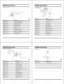
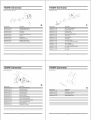
7500W Generator
Cylinder head system assy.
APA Part No. Description
APG3075_A-01-JD HEAD COVER COMP. BOLT
APG3075-A-02-JD HEAD COVER WASHER COMP
APG3075-A-03-JD WASHER COVER PACKING
APG3075-A-04-JD HEAD COVER COMP
APG3075-A-05-JD HEAD COVER PACKING
APG3075-A-06-JD FLANGE BOLT (M10X 80)
APG3075-A-07-JD SPARK PLUG
APG3075-A-08-JD EXHAUST PIPE STUD BOLT
APG3075_A-09-JD CYLINDER HEAD COMP
APG3075_A-10-JD CARBURETOR STUD BOLT
APG3075_A-11-JD CYLINDER HEAD SEALING PAD
APG3075_A-12_JD DOWEL PIN (q)10xq)12x20)
APG3075_A-13-JD AIR CLEANER STAY
33
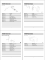
7500W Generator
Crankcase cover system assy.
:o
APA Part No.
APG3075-C-01 -JD
APG3075-C-02-JD
APG3075-C-03-JD
APG3075-C-04-JD
APG3075-C-05-JD
APG3075-C-06-JD
APG3075-C-07-JD
APG3075-C-08-JD
APG3075-C-09-JD
APG3075-C-10-JD
APG3075-C-11 -JD
APG3075-C-12-JD
APG3075-C-13-JD
APG3075-C-14-JD
APG3075-C-15-JD
APG3075-C-16-JD
/:%,
Description
DUCT COVER
FLANGE BOLT (M8 X 35)
OIL SCALE
OIL SCALE SEAL RING
OIL S EAL(q)35x¢52x8)
FLANGE BOLT (M8X35)
CRANKCASE COVER
GOVERNOR GEAR WASHER (6 mm)
GOVERNOR GEAR
SLIDER SHAFT
SLIDER WASHER (6 mm__
GOVERNOR SLIDER
BALL BEARING (6202)
BALL BEARING (6207)
CRANKCASE COVER PAD
DOWEL PIN (8X12)
A
C
7500W Generator
Cylinder barrel
e_. s
@ 7
APA Part No.
APG3075-B-01-JD
APG3075-B-02-JD
APG3075-B-03-JD
APG3075-B-04-JD
APG3705-B-05-JD
APG3075-B-06-JD
APG3075-B-07-JD
APG3075-B-08-JD
APG3075-B-09-JD
APG3075-B-10-JD
APG3075-B-11-JD
APG3075-B-12-JD
APG3075-B-13-JD
APG3075-B-14-JD
APG3075-B-15-JD
_s _4
4
B
7500W Generator
Crankshaft assy,
APA Part No.
APG3075-D-01-JD
APG3075-D-02-JD
Description
FLANGE BOLT (M6X 14)
OIL LEVEL SWITCH ASSY
O-RING
FLANGE NUT M(ML0_
CRANK CASE
BALL BEARING (6207)
WASHER(q)8.3x¢17x1))
LOCK PIN (10 ram)
GOVERNOR ARM SHAFT
OIL SEAL_
DRAIN PLUG WASHER 12mm
DRAIN PLUG BOLT
OIL SEAL (¢35xq)52x8)
OIL PROTECTOR
FLANGE BOLT
1
Description
CRANKSHAFT COMP
BALANCER WEIGHT
D

7500W Generator
Piston & Connecting Rod Assy.
10
8
APA Part No. Description
APG3075-E-01-JD COMPRESSION RING A
APG3075-E-02-JD COMPRESSION RING B
APG3075-E-03-JD OIL RING A
APG3075-E-04-JD OIL RING B
APG3075-E-05dD PISTON PIN CLIP (20 mm)
APG3075-E-06-JD PISTON
APG3075-E-07-JD PISTON PIN
APG3075-E-08-JD CONNECTING ROD
APG3075-E-09-JD CONNECTING COVER
APG3075-EN0-JD CONNECTING ROD BOLT
37
E
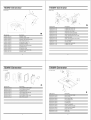
7500W Generator
Recoil Starter Assy.
7500W Generator
Recoil Starter Assy,
/1
APA Part No.
APGG7500-G-01-JD
APG3075-G-02-JD
APG3075-G-03*JD
APG3075-G-04-JD
APG3075-G-05-JD
APG3075-G-06-JD
APG3075-G-07-JD
APG3075-G-08-JD
APGG7500-G-09-JD
APG3075-G-10*JD
APG3075-G-11-JD
APG3075-G-12-JD
39
..........................................................................................................................J
Description
RECOIL STARTER ASSY
SETTING SCREW
SPRING RETAINER
PLATEN SPRING
STARTER DETENT
DETENT SPRING
RECOIL STARTER REEL
START RETURN SPRING
RECOIL STARTER CASE COMP
RECOIL STARTER ROPE
STARTER KNOB
FLANGE BOLT (M6X8)
G
APA Part No.
APG3075-F-01-JD
APG3075-F-02-JD
APG3075-F-03-JD
APG3075-F-04-JD
APG3075-F-05-JD
APG3075-F-06-JD
APG3075-F-07-JD
APG3075-F-08-JD
APG3075-F-09-JD
APG3075-F-10-JD
APG3075-F-11-JD
APG3075-F-12-JD
APG3075-F-13-JD
APG3075-F-14-JD
APG3075-F-15-JD
7 '%-j__
Description
PIVOT ADJUSTING NUT
ROCKER ARM PIVOT
ROCKER ARM
PIVOT BOLT M_
PUSH ROD GUIDE PLATE
ROD PUSH
VALVE LI FTE R
CAMSHAFT
VALVE ROTATOR
EX. VALVE SPRING RETAINER
VALVE SPRING
VALVE SPRING SEAT
IN. VALVE SPRING RETAINER
EX. VALVE
IN. VALVE
7500W Generator
Fan Cover Assy.
APA Part No. Description
APG3075-H-01-JD SHROUD
APG3075-H-02-JD FLANGE BOLT (M6 X 14)
APGG7500-H-03-JD FAN COVER COMP
APG3075-H-04-JD WIRE HARNESS CLIP
F
H

7500W Generator
Carburetor Assy.
APA Part No. Description
APG3075q-01-JD TUBE CLIP
APG3075q-02_JD TUBE A
APG3075q-03-JD TUBE B
APG3075q-04-JD WIPE HARNESS CLIP
APG3075q-05-JD DASHPOT CHECK VALVE
APG3075q-06-JD MANUAL CHOKE STAY ASSY
APG3075q-07_JD CARBURETOR IRON GASKET
APG3075q-08_JD CARBURETOR ASSY
APG3075q-09_JD CARBURETOR PAPER GASKET
APG3075qq 0-JD CARBURETOR INSULATING PLATE
APG3075qq 1-JD INTAKE PIPE GASKET
41
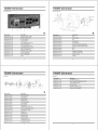
7500W Generator
Ignition System Assy.
7500W Generator
Flywheel Assy.
Y
U s _ C 3 ,
;;....._0]
4
APA Part No. Description
APG3075-J-01-JD FLYWHEEL
APG3075-J-02-JD SPECIAL WOODRUFF KEY
APG3075-J-03-JD COOLING FAN
APG3075-J-04-JD STARTER PULLEY
APG3075-J-05-JD FLYWHEEL NUT (M16)
7500W Generator
Starter Motor Assy.
APA Part No.
APG3075-K-01-JD
APG3075-K-02-JD
APG3075-K-03-JD
APG3075-K-04-JD
APG3075-K-05-JD
APG3075-K-06-JD
APG3075-K-07-JD
APG3075-K-08-JD
APG3075-K-09-JD
APG3075-K-10-JD
43
8
9
Description
NOISE SUPPERSSOR CAP ASSY
IGNITION COIL ASSY
STOP SWITCH CORD
STOP SWITCH CORD HOLDER
FLANGE BOLT (M6 X 25)
CORD GROMMENT
CHARGE COIL ASSY
FLANGE BOLT (M6 X 40)
CORD CLAMPER
FLANGE BOLT (M6X20)
K
APA Part No.
APG3075-L-01-JD
APG3075-L-02-J D
APG3075-L-03-J D
3
1
Description
UNIT STARTER MOTOR
CONTACTOR ASSY
FLANGE BOLT (M8x35)
J

7500W Generator
Control Assy.
M
7500W Generator
Muffler Assy.
.J'!
APA Part No. Descri tion
APG3075-M-01-JD
APG3075-M-02-JD
APG3075-M-03-JD
APG3075-M-04-JD
APG3075-M-05-JD
APG3075-M-06-JD
APG3075-M-07-JD
APG3075-M-08-JD
APG3075-M-09-JD
APG3075-Mq 0-JD
APG3075-Mq I-JD
7500W Generator
Air Cleaner
CONTROL ASSY
CONTROL BASE COMP
CONTROL ADJUSTING SPRING
PAN SCREW (M5 X 34)
FLANGE BOLT (M6 X 14)
GOVERNOR SPRING
THROTTLE RETURN SPRING
GOVERNOR ROD
FLANGE NUT (M6)
GOVERNOR ARM BOLT M_
CONTROL ARM
2
'6
,, 2
APA Part No. Description
APG3075_N_01-JD FLANGE BOLT (M8 X 16)
APG3075-N-02-JD FLANGE BOLT (M6 X 12)
APG3075-N-03-JD MUFFLER STAY COMP
APG3075-N-04-JD MUFFLER PROTECTOR SEAL
APG3075-N-05-JD MUFFLER SIDE PROTECTOR
APG3075_N_06-JD MUFF. INNER PROTECTOR COMP
APG3075_N_07_JD MUFFLER COMP
APG3075-N_08-JD MUFF. OUTER PROTECTOR COMP
APG3075_N_09-JD EX. PIPE GASKET
APG3075_Nq0-JD EX PIPE COMP
APG3075_Nq 1-JD FLANGE BOLT (M8 X 25)
APG3075-Nq2-JD FLANGE NUT (M8)
46
4
" -_ _\ o 7
,,,
3
12 11
APA Part No. Description
APGG7500-P-01-JD FUEL FILLER CAP COMP
APGG7500-P-02-JD FUEL FILTER
APGG7500-P-03-JD FUEL TANK COMP
APGG7500-P-04-JD FUEL METER ASSY
APGG7500-P-05-JD FLAT SCREW
APGG7500-P-06-JD FLANGE BOLT
APGG7500-P-07-JD AIR DUCT WASHER
APGG7500-P-08-JD TANK CUSHION COLLAR
APGG7500-P-09-JD CONTROL BOX RUBBER
APGG7500-P-10-JD FUEL TANK JOINT
APGG7500-P-11-JD TUBE CLIP
APGG7500-P-12-JD FUEL TUBE
48
O
7500W Generator
Fuel Tank Assy.
APA Part No. Description
APG3075-O-01-JD AIR CLEANER COVER COMP
APG3075-O-02-JD AIR CLEANER ELEMENT
APG3075-O-03-JD FLANGE NUT (M5)
APG3075-O-04-JD AIR CLEANER SEPARATOR
APG3075-O-05-JD AIR CLEANER SEAL
APG3075-O-06-JD AIR CLEANER CASE COMP
APG3075-O-07-J D BREATH ER GASKET
N
P

7500W Generator
Control BOX Assy.
4
APA Part No. Description
APGG7500-Q-01-JD CONTROL PANEL COMP
APGG7500-Q-02-JD ENGINE SWITCH ASSY
APGG7500-Q-03-JD DC 12V OUTPUT
APGG7500-Q-04-J D HOURS METER
APGG7500-Q-05-J D 120V RECEPTACLE(Ru-22)
APGG7500-Q-06-J D CIRCUIT BREAKER
APGG7500-Q-07-J D 120V RECEPTACLE(L5-30)
APGG7500-Q-08-J D 240V RECEPTACLE(L14-30)
APGG7500-Q-09-JD EARTH TERMINAL SET
APGG7500-Q-10-JD CONTROL PANEL CASE
APGG7500-Q-11-JD CIRCUIT BREAKER
APGG7500-Q-12-JD CIRCUIT BREAKER
APGG7500-Q-13-JD LAMP
49
7500W Generator
Generator
17
i
APA Part No. Description
APG3075-S-01-JD STATOR COVER
APG3075-S-02-JD STATORASSY
APG3075-S-03-JD COOLING FAN
APG3075-S-04-JD BRUSH ASSY.
APG3075-S-05-JD TAPPING SCREW
APG3075-S-06-JD RR HOUSING
APG3075-S-07-JD PAN SCREW
APG3075-S-08-JD FLANGE BOLT (M6X 179)
APG3075-S-09-JD AUTO VOLTAGE REG. ASSY
APGG7500-S-10-JD GENERATOR COVER
APG3075-S-11-JD CABLE TIE
APG3075-S-12-JD FLANGE BOLT
APG3075-S-13-JD ROTOR COMP
APG3075-S-14-JD BEARING ASSY
APG3075-S-15-JD PLAIN WASHER
APG3075-S-16-JD FLANGE BOLT (M10)
APG3075-S-17-JD FLANGE BOLT (M5)
51
lo
Q
2
S
7500W Generator
Frame Comp Assy.
APA Part No. Description
APGG7500-R-01-J D BOLT
APGG7500-R-02-J D REAR COVER
APGG7500-R-03-J D NUT
APGG7500-R-04-J D FLANGE NUT
APGG7500-R-05-J D FLANGE BOLT
APGG7500-R-06-J D MUFFLER SUPPORTER(UPPER)
APGG7500-R-07-J D MUFFLER SUPPORTER(NETHER)
APGG7500-R-08-J D BOLT
APGG7500-R-09-J D NUT
APGG7500-Rq 0-JD GENERATOR FRAME
APGG7500-Rq 1-JD CONTROL PANEL BOX
APGG7500-Rq 2-JD FRONT COVER
APGG7500-Rq 3-JD SCREW
50
7500W Generator
R
Generator
APG3075-S-18-JD HEX.BOLT (M5 X 20)
APG3075-S-19-JD VOLT CHANGE TERMINAL BR-AC-W
APG3075-S-20-JD PLAIN WASHER 5m_
APG3075-S-21-JD HEX. NUT M_
APG3075-S-22-JD SPRING WASHER (5mm)
APG3075-S-23-JD CRANK CASE GROMMET

7500W Generator
Wheel & Hand Assy. ? 7
7_
',._ _ 7 7
912 6 ; 46/_/
'2z l-_-'4,0-,4
APA Part No. Description
APGG7500-%01-JD PIN SPLIT
APGG7500-%02-JD WSHER PLAIN
APGG7500-%03-JD WHEEL
APGG7500-%04-JD BAFFLE
APGG7500-%05-JD SHAFT
APGG7500-%06-JD FLANGE BOLT (M6X 35)
APGG7500-%07-JD FLANGE NUT
APGG7500-%08-JD RUBBER BOLT
APGG7500-%09-JD FLANGE NUT
_G7500-%10-JD _TANDER
APGG7500-%11-JD FLANGE BOLT M6X_
APGG7500-%12-JD NUT
APGG7500-%13-JD HANDLE
APGG7500-%14-JD BOLT
APGG7500-%15-JD BRACKET WITH LOCK PIN
APGG7500-%16-JD FLANGE BOLT
53
2 1
T
Distributed by:
ALL-POWER AMERICA
730 S.Ebpelson Dr.
City Of tndustry,CA91748
www allpowe_ ame_ica.com
-
 1
1
-
 2
2
-
 3
3
-
 4
4
-
 5
5
-
 6
6
-
 7
7
-
 8
8
-
 9
9
-
 10
10
-
 11
11
-
 12
12
-
 13
13
-
 14
14


All-Power APGG7500 Owner's manual
- Category
- Power generators
- Type
- Owner's manual
Ask a question and I''ll find the answer in the document
Finding information in a document is now easier with AI
Related papers
-
All-Power APG3075 Owner's manual
-
-
-
-
-
-
-
All-Power APG3012 Owner's manual
-
-
Other documents
-
All Power APGG6000 Owner's manual
-
Pulsar PG7750B Installation guide
-
-
-
-
-
-
-
Steele SP-GG350 Owner's manual
-
 Ironton 190F Owner's manual
