ESAB INSTALLATION AIR COMPRESSOR KIT MA-5040DD Installation guide
- Category
- Welding System
- Type
- Installation guide
This manual is also suitable for

INSTALLATION INSTRUCTIONS FOR
AIR COMPRESSOR KIT
MA-5040DD
For the Following Assemblies:
•
494200
OWNER’S MANUAL Number 430429-198
Revised December 1, 1997
THERMAL ARC INC., TROY, OHIO 45373-1085, U.S.A.
IMPORTANT: Readtheseinstructionsbeforeinstalling, operating, or servicing this system.


PROTECT YOURSELF AND OTHERS FROM POSSIBLE SERIOUS INJURY OR DEATH. KEEP CHILDREN AWAY. PACEMAKER
WEARERSKEEPAWAY UNTIL CONSULTINGYOURDOCTOR. DO NOTLOSETHESEINSTRUCTIONS.READOPERATING/INSTRUC-
TION MANUAL BEFORE INSTALLING, OPERATING OR SERVICING THIS EQUIPMENT.
Welding products and welding processes can cause serious injury or death, or damage to other equipment or property, if the operator does
not strictly observe all safety rules and take precautionary actions.
Safe practices have developed from past experience in the use of welding and cutting. These practices must be learned through study and
trainingbefore using thisequipment. Anyone not having extensivetraining inwelding and cuttingpractices should notattemptto weld. Certain
of the practices apply to equipment connected to power lines; other practices apply to engine driven equipment.
Safe practices are outlined in the American National Standard Z49.1 entitled:
SAFETY IN WELDING AND CUTTING. This publication and
other guides to what you should learn before operating this equipment are listed at the end of these safety precautions.
HAVE ALL INSTALLATION, OPERATION, MAINTENANCE, AND REPAIR WORK PERFORMED ONLY BY QUALIFIED PEOPLE.
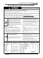
ELECTRIC SHOCK can kill.
Touchinglive electricalparts cancause fatalshocks
or severe burns. The electrode and work circuit is
electricallylive wheneverthe output ison. Theinput
power circuit and machine internal circuits are also
livewhenpowerison.Insemiautomaticorautomatic
wire welding, the wire, wire reel, drive roll housing,
and all metal parts touching the welding wire are
electrically live. Incorrectly installed or improperly
grounded equipment is a hazard.
1. Do not touch live electrical parts.
2. Wear dry, hole-free insulating gloves and body protection.
3. Insulate yourself fromwork andground usingdry insulatingmats
or covers.
4. Disconnect input power or stop engine before installing or serv-
icing this equipment. Lock input power disconnect switch open,
or remove line fuses so power cannot be turned on accidentally.
5. Properly install and ground this equipment according to its
Owner’s Manual and national, state, and local codes.
6. Turn off all equipment when not in use. Disconnect power to
equipment if it will be left unattended or out of service.
7. Use fully insulated electrode holders. Never dip holder in water
to coolit or lay it down on the ground or the worksurface. Do not
touch holders connected to two welding machines at the same
time or touch other people with the holder or electrode.
8. Do notuseworn,damaged, undersized,orpoorly splicedcables.
9. Do not wrap cables around your body.
10. Ground the workpiece to a good electrical (earth) ground.
11. Do not touch electrode while in contact with the work (ground)
circuit.
12. Useonlywell-maintainedequipment.Repairorreplacedamaged
parts at once.
13. In confined spaces or damp locations, do not use a welder with
AC output unless it is equipped with a voltage reducer. Use
equipment with DC output.
14. Wear a safety harness to prevent falling if working above floor
level.
15. Keep all panels and covers securely in place.
ARC WELDING SAFETY INSTRUCTIONS AND WARNINGS
ARC RAYS can burn eyes and skin;
NOISE can damage hearing.
Arc rays from the welding process produce intense
heat and strong ultraviolet rays that can burn eyes
and skin. Noise from some processes can damage
hearing.
1. Wear a welding helmet fitted with a proper shade of filter (see
ANSI Z49.1 listed in Safety Standards) to protect your face and
eyes when welding or watching.
2. Wear approved safety glasses. Side shields recommended.
3. Use protective screens or barriers to protect others from flash
and glare; warn others not to watch the arc.
4. Wear protective clothing made from durable, flame-resistant
material (wool and leather) and foot protection.
5. Use approved ear plugs or ear muffs if noise level is high.
ARC WELDING can be hazardous.
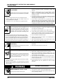
Eye protection filter shade selector for welding or cutting (goggles or helmet), from AWS A6.2-73.
Welding or Cutting
Operation
Torch soldering
Torch brazing
Oxygen cutting
Light
Medium
Heavy
Gas welding
Light
Medium
Heavy
Shielded metal-arc welding
(stick) electrodes
Welding or Cutting
Operation
Gas metal-arc welding (MIG)
Non-ferrous base metal
Ferrous base metal
Gastungstenarc welding(TIG)
Atomic hydrogen welding
Carbon arc welding
Plasma arc welding
Carbon arc air gouging
Light
Heavy
Plasma arc cutting
Light
Medium
Heavy
Electrode Size
Metal Thickness
or Welding Current
—
—
Under 1 in., 25 mm
1 to 6 in., 25-150 mm
Over 6 in., 150 mm
Under 1/8 in., 3 mm
1/8 to 1/2 in., 3-12 mm
Over 1/2 in., 12 mm
Under 5/32 in., 4 mm
5/32 to 1/4 in., 4 to 6.4 mm
Over 1/4 in., 6.4 mm
Electrode Size
Metal Thickness
or Welding Current
All
All
All
All
All
All
Under 300 Amp
300 to 400 Amp
Over 400 Amp
Filter
Shade
No.
2
3or4
3or4
4or5
5or6
4or5
5or6
6or8
10
12
14
Filter
Shade
No.
11
12
12
12
12
12
12
14
9
12
14
ARC WELDING SAFETY INSTRUCTIONS AND WARNINGS
Instruction 830001
May 8, 1996 2-1

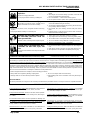
WELDING can cause fire or explosion.
Sparks and spatter fly off from the welding arc. The
flying sparks and hot metal, weld spatter, hot work-
piece, and hot equipment cancause fires and burns.
Accidental contact of electrode or welding wire to
metal objects can cause sparks, overheating, or fire.
1. Protect yourself and others from flying sparks and hot metal.
2. Do not weld where flying sparks can strike flammable material.
3. Remove all flammables within 35 ft (10.7 m) of the welding arc.
If this is not possible, tightly cover them with approved covers.
4. Be alert that welding sparks and hot materials from welding can
easily go through small cracks and openings to adjacent areas.
5. Watch for fire, and keep a fire extinguisher nearby.
6. Be aware that welding on a ceiling, floor, bulkhead, or partition
can cause fire on the hidden side.
7. Do not weld on closed containers such as tanks or drums.
8. Connect work cable to the work as close to the welding area as
practical to prevent welding current from traveling long, possibly
unknown paths and causing electric shock and fire hazards.
9. Do not use welder to thaw frozen pipes.
10. Remove stick electrode from holder or cut off welding wire at
contact tip when not in use.
11. Wear oil-free protective garments such as leather gloves, heavy
shirt, cuffless trousers, high shoes, and a cap.
FLYING SPARKS AND HOT METAL can
cause injury.
Chipping and grinding cause flying metal. As welds
cool, they can throw off slag.
1. Wear approved face shield or safety goggles. Side shields rec-
ommended.
2. Wear proper body protection to protect skin.
CYLINDERS can explode if damaged.
Shielding gas cylinders contain gas under high pres-
sure. If damaged, a cylinder can explode. Since gas
cylinders are normally part of the welding process,
be sure to treat them carefully.
1. Protectcompressedgascylindersfromexcessiveheat,mechani-
cal shocks, and arcs.
2. Install and secure cylinders in an upright position by chaining
themtoastationarysupportorequipmentcylinderracktoprevent
falling or tipping.
3. Keep cylinders awayfrom anywelding orother electricalcircuits.
4. Never allow a welding electrode to touch any cylinder.
5. Use only correct shielding gas cylinders, regulators, hoses, and
fittings designed for the specific application; maintain them and
associated parts in good condition.
6. Turn face away from valve outlet when opening cylinder valve.
7. Keep protective cap in place over valve except when cylinder is
in use or connected for use.
8. Readand follow instructions on compressed gas cylinders, asso-
ciated equipment, and CGA publication P-1 listed in Safety
Standards.
ENGINES can be hazardous.
ENGINE EXHAUST GASES can kill.
Engines produce harmful exhaust gases.
1. Use equipment outside in open, well-ventilated areas.
2. If used in a closed area, vent engine exhaust outside and away
from any building air intakes.
FUMES AND GASES can be hazardous
to your health.
Weldingproducesfumesandgases.Breathingthese
fumes and gases can be hazardous to your health.
1. Keep your head out of the fumes. Do not breath the fumes.
2. If inside, ventilate the area and/or use exhaust at the arc to
remove welding fumes and gases.
3. If ventilation is poor, use an approved air-supplied respirator.
4. Read the Material Safety Data Sheets (MSDSs) and the manu-
facturer’s instruction for metals, consumables, coatings, and
cleaners.
5. Work in a confined space only if it is well ventilated, or while
wearing an air-supplied respirator. Shielding gases used for
welding can displace air causing injury or death. Be sure the
breathing air is safe.
6. Do not weld in locations near degreasing, cleaning, or spraying
operations. The heat and raysof the arc canreact with vaporsto
form highly toxic and irritating gases.
7. Do not weld on coated metals, such as galvanized, lead, or
cadmium plated steel, unless the coating is removed from the
weld area, the area is well ventilated, and if necessary, while
wearing an air-supplied respirator. The coatings and any metals
containing these elements can give off toxic fumes if welded.
ARC WELDING SAFETY INSTRUCTIONS AND WARNINGS
Instruction 830001
2-2 May 8, 1996

STEAM AND PRESSURIZED HOT
COOLANT can burn face, eyes, and
skin.
The coolant inthe radiatorcan bevery hotand under
pressure.
1. Do not remove radiator cap when engine is hot. Allow engine to
cool.
2. Wear gloves and put a rag over cap area when removing cap.
3. Allow pressure to escape before completely removing cap.
PRINCIPAL SAFETY STANDARDS
Safety inWelding andCutting, ANSIStandard Z49.1,fromAmerican
Welding Society, 550 N.W. LeJeune Rd., Miami, FL 33126.
Safetyand Health Standards, OSHA29 CFR1910,from Superinten-
dent of Documents, U.S. Government Printing Office, Washington,
D.C. 20402.
Recommended Safe Practices for the Preparation for Welding and
CuttingofContainersThatHaveHeldHazardousSubstances,Ameri-
can Welding Society Standard AWS F4.1, from American Welding
Society, 550 N.W. LeJeune Rd., Miami, FL 33126.
National Electrical Code, NFPA Standard 70, from National Fire
Protection Association, Batterymarch Park, Quincy, MA 02269.
Safe Handling of Compressed Gases in Cylinders, CGA Pamphlet
P-1, from Compressed Gas Association, 1235 Jefferson Davis High-
way, Suite 501, Arlington, VA 22202.
Code forSafety inWelding andCutting, CSAStandardW117.2, from
Canadian Standards Association, Standards Sales, 178 Rexdale
Boulevard, Rexdale, Ontario, Canada M9W 1R3.
Safe Practices for Occupation and Educational Eye and Face Pro-
tection, ANSI Standard Z87.1, from American National Standards
Institute, 1430 Broadway, New York, NY 10018.
Cutting and Welding Processes, NFPA Standard 51B, from National
Fire Protection Association, Batterymarch Park, Quincy, MA 02269.
SPARKS can cause BATTERY GASES
TO EXPLODE; BATTERY ACID can
burn eyes and skin.
Batteriescontainacidandgenerateexplosivegases.
1. Always wear a face shield when working on a battery.
2. Stop engine before disconnecting or connecting battery cables.
3. Do not allow tools to cause sparks when working on a battery.
4. Do not use welder to charge batteries or jump start vehicles.
5. Observe correct polarity (+ and –) on batteries.
MOVING PARTS can cause injury.
Moving parts,such as fans,rotors, and beltscan cut
fingers and hands and catch loose clothing.
1. Keep all doors, panels, covers, and guards closed and securely
in place.
2. Stop engine before installing or connecting unit.
3. Have only qualified people remove guards or covers for mainte-
nance and troubleshooting as necessary.
4. Toprevent accidental starting duringservicing, disconnectnega-
tive (-) battery cable from battery.
5. Keep hands, hair, loose clothing, and tools away from moving
parts.
6. Reinstall panels or guards and close doors when servicing is
finished and before starting engine.
ENGINE FUEL can cause fire or
explosion.
Engine fuel is highly flammable.
1. Stop engine before checking or adding fuel.
2. Donot addfuel whilesmokingor ifunitisnearanysparksoropen
flames.
3. Allow engine to cool before fueling. If possible, check and add
fuel to cold engine before beginning job.
4. Do not overfill tank — allow room for fuel to expand.
5. Do not spill fuel. If fuel is spilled, clean up before startingengine.
NOTE: Considerations About Welding And The Effects Of Low Frequency Electric And Magnetic Fields
The following is a quotation from the General Conclusions Section of the U.S. Congress, Office of Technology Assessment,
Biological Effects
of Power Frequency Electric & Magnetic Fields — Background Paper, OTA-BP-E-63 (Washington, DC: U.S. Government Printing Office, May
1989): “... there is now a very large volume of scientific findings based on experiments at the cellular level and from studies with animals and
people which clearly establish that low frequency magnetic fields can interact with, and produce changes in, biological systems. While most of
this work is of very high quality, the results are complex. Current scientific understanding does not yet allow us to interpret the evidence in a
single coherent framework. Even more frustrating, it does not yet allow us to draw definite conclusions about questions of possible risk or to
offer clear science-based advice on strategies to minimize or avoid potential risks.”
To reduce magnetic fields in the workplace, use the following procedures:
About Pacemakers:
The above procedures are among those also normally recommended for pacemaker wearers. Consult your doctor for complete information.
1. Keep cables close together by twisting or taping them.
2. Arrange cables to one side and away from the operator.
3. Do not coil or drape cables around the body.
4. Keep welding power source and cables as far away from body as
practical.
WARNING: This product, when used for welding or cutting, produces fumes or gases which contain chemicals known to the State
of California to cause birth defects and, in some cases, cancer. (California Health & Safety Code Sec. 25249.5 et seq.)
ARC WELDING SAFETY INSTRUCTIONS AND WARNINGS
Instruction 830001
May 8, 1996 2-3

This page intentionally left blank.
ARC WELDING SAFETY INSTRUCTIONS AND WARNINGS
Instruction 830001
2-4 May 8, 1996

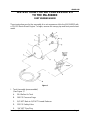
INSTRUCTIONS FOR AIR COMPRESSOR KIT
TO THE MA-5040DD
PART NUMBER 494200
These instructions are for the assembly of an air compressor kit to the MA-5040DD with
a F3L-912 Deutz Diesel Engine. To begin, remove the canopy top and front panel sheet
metal.
I. Tank Assembly (preassembled)
(See Figure 1)
A. 30.4 Gallon Air Tank
B. 160 PSI Pressure Gage
C. 3/4" NPT Male to 1/4" NPT Female Reducer
D. 125 PSI Safety Valve
E. 3/4" NPT Pipe Plug
Figure 1
430429-198
December 1, 1997 Revised Page 1

F. 1/2" NPT Gate Valve
G. 3/4" NPT Male to 1/2" NPT Male Adapter
H. 1-1/2" NPT Pipe Plug
I. 1-1/2" NPT Male to 3/4" NPT Female Reducer
J. 3/4" NPT Male to 1/2" NPT Female Adapter
K. 5/8" JIC Flare to 1/2" NPT Male Connector
II. Regulator Assembly
(See Figure 1)
2. Regulator mounting plate
3. Screw, cap, hex head, M12 x 24.5mm (2) req’d
4. Washer, lock, M12 (2) req’d
5. Regulator, Wabco 003
Mount the Regulator (item 5) to the mounting plate (item 2) using the 10mm nut and lock
washer furnished with the regulator. Mount the Regulator mounting plate (item 2) to the
engine, below the starter, using the two 12mm screws and lock washers (items 3 and 4).
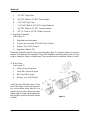
III. Drive Pulley
(See Figure 2)
6. Pulley, drive, two groove
7. Stud, M8 x 33mm (4) req’d
8. Nut, hex, M8 (4) req’d
9. Washer, lock, M8 (4) req’d
Install the four M8 studs (item 7) into
four of the holes in the crankshaft pul-
ley, use the drive pulley (item 6) as a
guide to which holes. Mount the drive
pulley (item 6) to the crankshaft pulley
withtheM8nutandlock washer (items
8 and 9).
Figure 2
430429-198
Page 2 December 1, 1997 Revised

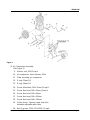
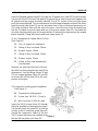
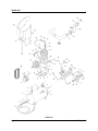
IV. Air Compressor Assembly
(See Figure 3)
9. Washer, lock, M8 (9) req’d
10. Air compressor, Knorr-Bremse, 300cc
11. Plate, mounting, air compressor
12. O-ring, 32mm OD
13. O-ring, 24mm OD
14. Screw, Allen head, M8 x 35mm (2) req’d
15. Screw, Hex head, M8 x 35mm (4) req’d
16. Screw, Hex head, M8 x 40mm
17. Screw, Hex head, M8 x 100mm
18. Screw, Hex head, M8 x 120mm
19. Pulley, driven, 2 groove, taper hub, pitch
diameter adjustable with shims
39. Belt, V-groove, 2200, 12.5x1100 (2) req’d
Figure 3
430429-198
December 1, 1997 Revised Page 3

Remove (2) M8 bolts and oil return plug from the front of the engine, see Figure 3 for
location. Insert the 32mm O-ring (item 12) between the air compressor mounting plate
(item 11) and the engine block. The O-ring should line up with the oil return plug hole.
Attach the mounting plate (item 11) to the engine using the (3) longer M8 screws and lock
washers (items 16, 17, 18 and 9) in the front and the (2) Allen head M8 screws and lock
washers (items 9 and 14) on the top.
Insertthe24mmO-ring(item13) inthebottomofthecompressor, betweenthecompressor
(item 10) and the mounting plate (item 11). Attach the driven pulley (item 19) to the
compressor (item 10). Attach the (2) belts (item 39) to the driven pulley (item 19) and the
drive pulley (item 6). Secure the compressor to the mounting plate with the (4) M8 x 35mm
screws and lock washers (items 15 and 9). If belt tensioning is required, remove shims
between the compressor driven pulley halves to adjust the pitch.
V. Air Cleaner to Intake Manifold Hose
(See Figure 4)
20. Hose, air intake extension, “Z” Shaped
21. Collar, steel, 2-3/16" OD x 1" long
22. Flanged adapter with M23 hex nut and flat washer
Figure 4
430429-198
Page 4 December 1, 1997 Revised

23. Clamps, hose, 3-1/8" (2) req’d
Insert the flanged adapter (item 22) through the Z-shaped hose (item 20) from the inside.
Secure with the M23 nut and flat washer. Remove the air intake hose from between the
air cleaner and the engine air intake manifold. Cut off 5.5 inches of this hose (the larger
end) at the manifold end. This should remove all of the larger diameter portion of the hose.
Insert the steel collar (item 21) into the air intake hose in the end that was previously cut.
The collar should be flush with the end of the hose. Insert this end of the air intake hose
into the Z-shaped hose and clamp with one of the hose clamps (item 23). Re-install this
air intake hose assembly onto the engine with the Z-shaped hose end going to the engine
intake manifold. Clamp with the second hose clamp (item 23).
VI. Air Compressor to Engine Block Oil Line
(See Figure 3)
24. Line, oil, engine to compressor
25. Fitting, oil line, hex head, 10mm
26. Gasket, copper, 10mm
27. Fitting, oil line, hex head, 12mm
28. Gasket, copper, 12mm
29. Clamp, oil line, outer formed piece
(not required)
Remove one plug from the side of the en-
gine block and one plug from the side of the
compressor. Use the fittings (items 25 and
27) and copper gaskets (items 26 and 28)
to connect the oil line (item 24) to the com-
pressor and engine.
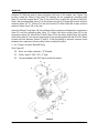
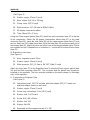
VII.Compressor cooling guard Installation
(See Figure 5)
40. Compressor cooling guard
41. Screw, hex, 1/4-20 x 1 (2) req’d
42. Nut, hex, keps, 1/4-20 (4) req’d
Insert the 1/4-20 screws (item 41) through
the holes available on the engine as shown.
Secure with keps nuts (item 42) to hold the
screws in place. Install the guard (item 40)
around the compressor. Attach to the two
1/4-20 screws that were just installed using
the two left over keps nuts (item 42).
Figure 5
430429-198
December 1, 1997 Revised Page 5

VIII. Air cleaner hose to compressor inlet hose
(See Figure 4)
33. Gasket, copper, 27mm (1) req’d
34. Hose, rubber, 5/8", 16 to 18" long
35. Clamp, hose, 5/8" (2) req’d
36. Male connector, 1/2" OD tube to M26x1.5 Male
37. 90 degree compression elbow
38. Tube, 18mm OD x 3" long
Using the 27mm copper gasket (item 33), attach the male connector (item 36) to the top
of the compressor. Attach the 90 degree compression elbow (item 37) to the male
connector (item 36). Insert the tube (item 38) into the compression elbow (item 37) and
secure. Attach the 5/8" rubber hose (item 34) to the tube (item 38) and secure with one of
the clamps (item 35). Attach the otherend of the hose to the flanged adapter (item 22) that
was installed on the Z-shaped hose in Instruction V., secure with the second hose clamp
(item 35).
IX. Regulator to tank hose
(See Figure 1)
31. Hose, regulator to tank, 8 foot
54. Gasket, copper, 22mm (1) req’d
55. Male connector, 5/8" JIC flare to 3/4" NPT Male (1) req’d
Attach the hose (item 31) to the Regulator (item 5) using the 22mm copper gasket (item
54) and the Male connector (item 55). The connector and the gasket may already be
installed on the regulator. The hose must be installed on the down stream, or discharge
side, of the regulator.
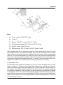
X. Compressor to Regulator Tube
(See Figure 6)
32. Special bent steel, 5/8" OD, air tube, with flare adapter 5/8" JIC Female nut
and flare adapter sleeve on each end
33. Gasket, copper, 27mm (1) req’d
44. Screw, hex, socket head, 1/4 x 5/8 (2) req’d
45. Washer, lock, 1/4 (2) req’d
46. Screw, HHC, M8 x 35mm
47. Washer, lock, M8
48. Washer, flat, M8
49. Adjustable air tube support bracket, 6" x 5/8"
430429-198
Page 6 December 1, 1997 Revised

50. Clamp, conduit, 1/2" EMT (2) req’d
51. Tyrap, 5"
52. Adapter, 3/4" NPT Female to M26 x 1.5 Male
53. 90 degree male elbow 5/8" JIC flare to 3/4" NPT Male
54. Gasket, copper, 22mm (1) req’d
55. Male connector, 5/8" JIC flare to 3/4" NPT Male (1) req’d
Attach adapter (item 52) to compressor using the 27mm copper gasket (item 33). Install
the 90 degree elbow (item 53) to the adapter (item 52). Be sure to use thread sealant.
Attach male connector (item 55) to the regulator (item 5) using the 22mm copper gasket
(item 54). This may already be done on some kits. Attach the special bent steel tube (item
32) to the compressor and the regulator. Attach the 6" support bracket (item 49) to the
engine block using the M8 hardware (items 46, 47 and 48). Secure the steel tubing to the
support bracket with the conduit clamps and hardware (items 44, 45 and 50).
XI. Operational Test
This completes the compressor installation. Be sure the air tank discharge valve is closed
(item F in Figure 1). Start the unit and allow the compressor to build up air in the tank.
When the pressure gage reads approximately 100 PSI the compressor should unload. As
this happens, there will be a loud “banging” sound. That sound is the regulator beginning
to unload the compressor. With your hand you should feel an air discharge at the bottom
of the regulator. Open the air tank discharge valve slowly and watch the air tank pressure
gage.Whenthepressurereachesapproximately95PSIthecompressorshouldloadagain,
there should no longer be any air escaping from the bottom of the regulator. Shut the unit
off and check for air leaks.
Figure 6
430429-198
December 1, 1997 Revised Page 7

XII.General Specifications
Compressor Make: Knorr-Bremse, 300cc
Approximately 4 HP
Air Delivery:
15 CFM at 0 PSI
13 CFM at 60 PSI
12 CFM at 90 PSI
11 CFM at 120 PSI
NOTE: These air deliveries are based on continuous usage. It is what the
compressor is capable of. Higher deliveries are possible for shorter times.
Compressor Unload Pressure: 100 PSI
Compressor Load Pressure: 95 PSI
430429-198
Page 8 December 1, 1997 Revised

This page intentionally left blank.
430429-198
December 1, 1997 Revised Page 9

Parts List
430429-198
Page 10 December 1, 1997 Revised

MA-5040DD Air Compressor Kit
PARTS LIST
1. Tank Assembly — including the following parts:
A. 30.4 gallon air tank
B. 160 PSI pressure gage
C. 3/4" NPT Male to 1/4" NPT Female Reducer
D. 125 PSI Safety Valve
E. 3/4" NPT pipe plug
F. 1/2" NPT Gate Valve
G. 3/4" NPT Male to 1/2" NPT Male Adapter
H. 1-1/2" NPT pipe plug
I. 1-1/2" NPT Male to 3/4" NPT Female Reducer
J. 3/4" NPT Male to 1/2" NPT Female Adapter
K. 5/8" JIC Flare to 1/2" NPT Male Connector
2. Regulator mounting plate
3. Screw, cap, hex head, M12 x 24.5mm (2) req’d
4. Washer, lock, M12 (2) req’d
5. Regulator, Wabco 003
6. Pulley, drive, two groove
7. Stud, M8 x 33mm (4) req’d
8. Nut, hex, M8 (4) req’d
9. Washer, lock, M8 (13) req’d
10. Air compressor, Knorr-Bremse, 300cc
11. Plate, mounting, air compressor
12. O-ring, 32mm OD
13. O-ring, 24mm OD
14. Screw, Allen Head, M8 x 35mm (2) req’d
15. Screw, Hex head, M8 x 35mm (4) req’d
16. Screw, Hex head, M8 x 40mm
17. Screw, Hex head, M8 x 100mm
18. Screw, Hex head, M8 x 120mm
19. Pulley, driven, 2 groove, taper hub, pitch diameter adjustable with shims
20. Hose, air intake extension, “Z” shaped
21. Collar, steel, 2-3/16" OD x 1" long
22. Flanged adapter with M23 hex nut and flat washer
23. Clamps, hose, 3-1/8" (2) req’d
24. Line, oil, engine to compressor
25. Fitting, oil line, hex head, 10mm
26. Gasket, copper, 10mm
27. Fitting, oil line, hex head, 12mm
28. Gasket, copper, 12mm
29. Clamp, oil line, outer formed piece (not required)
30. Clamp, oil line, inner flat plate (not required)
31. Hose, regulator to tank, 8 foot
32. Special bent steel, 5/8" OD, air tube, with flare adapter 5/8" JIC Female nut and flare
adapter sleeve on each end
33. Gasket, copper, 27mm (2) req’d
34. Hose, rubber, 5/8", 16 to 18" long
35. Clamp, hose, 5/8" (2) req’d
36. Male connector, 1/2" OD tube to M26x1.5 Male
37. 90 degree compression elbow
38. Tube, 18mm OD x 3" long
39. Belt, V-groove, 2200, 12.5x1100 (2) req’d
40. Compressor cooling guard
41. Screw, hex, 1/4-20 x 1 (2) req’d
42. Nut, hex, keps, 1/4-20 (4) req’d
43. Washer, flat, 1/4 (5)
44. Screw, hex, socket head, 1/4 x 5/8
(2) req’d
45. Washer, lock, 1/4 (2) req’d
46. Screw, HHC, M8 x 35mm
47. Washer, lock, M8
48. Washer, flat, M8
49. Adjustable air tube support bracket,
6" x 5/8"
50. Clamp, conduit, 1/2" EMT (2) req’d
51. Tyrap, 5"
52. Adapter, 3/4" NPT Female to
M26 x 1.5 Male
53. 90 degree male elbow 5/8" JIC flare
to 3/4" NPT Male
54. Gasket, copper, 22mm (2) req’d
55. Male connector, 5/8" JIC flare to 3/4"
NPT Male (2) req’d
430429-198
December 1, 1997 Revised Page 11

This page intentionally left blank.
430429-198
Page 12 December 1, 1997 Revised

STATEMENT OF WARRANTY
LIMITED WARRANTY: ThermalArc
®
, Inc., AThermadyne Company, warrantsthat itsproducts will befree of defectsin workmanship
ormaterial.Shouldany failureto conform tothiswarranty appearwithin thetime periodapplicable tothe Thermal Arcproductsas stated
below, Thermal Arc shall, upon notification thereof and substantiation that the product has been stored, installed, operated, and
maintained in accordance withThermal Arc’sspecifications,instructions, recommendationsand recognizedstandard industry practice,
and not subject to misuse, repair, neglect, alteration, or accident, correct such defects by suitable repair or replacement, at Thermal
Arc’s sole option, of any components or parts of the product determined by Thermal Arc to be defective.
THERMAL ARC MAKES NO OTHER WARRANTY, EXPRESS OR IMPLIED. THIS WARRANTY IS EXCLUSIVE AND IN LIEU OF
ALL OTHERS, INCLUDING, BUT NOT LIMITED TO ANY WARRANTY OF MERCHANTABILITY OR FITNESS FOR ANY
PARTICULAR PURPOSE.
LIMITATION OF LIABILITY: Thermal Arc shall not under any circumstances be liable for special or consequential damages, such as,
but not limited to, damage or loss of purchased or replacement goods, or claims of customers of distributor (hereinafter “Purchaser”)
for service interruption. The remedies of the Purchaser set forth herein are exclusive and the liabilityof Thermal Arcwith respect to any
contract, or anything done in connection therewith such as the performance or breach thereof, or from the manufacture, sale, delivery,
resale, or use of any goods covered by or furnished by Thermal Arc whether arising out of contract, negligence, strike tort, or under
any warranty, or otherwise, shall not, except as expressly provided herein, exceed the price of the goods upon which such liability is
based. No employee, agent, or representative of Thermal Arc is authorized to change this warranty in any way or grant any other
warranty.
PURCHASER’SRIGHTSUNDERTHISWARRANTYAREVOIDIFREPLACEMENTPARTSORACCESSORIESAREUSEDWHICH
IN THERMAL ARC’S SOLE JUDGMENT MAY IMPAIR THE SAFETY OR PERFORMANCE OF ANY THERMAL ARC PRODUCT.
PURCHASER’S RIGHTS UNDER THIS WARRANTY ARE VOID IF THE PRODUCT IS SOLD TO PURCHASER BY
NON-AUTHORIZED PERSONS.
Except with regards to the products listed below, this warranty shall remain effective three (3) years from the date Thermal Arc’s
authorized distributor delivers the product to Purchaser, but in no event more than (4) years from the date Thermal Arc delivers the
product to the authorized distributor.
Shorter warranty periods apply to the products listed below. On these products, the warranty is effective for the time stated below
beginning on the date that the authorized distributor deliversthe productsto the Purchaser. Notwithstanding the foregoing, in no event
shall the warranty period extend more than the time stated plus one year from the date Thermal Arc delivered the product to the
authorized distributor.
ALL OTHER P-WEE, PRO-LITE
POWER SUPPLIES POWER SUPPLIES PRO-PLUS, PRO-WAVE LABOR
MAIN POWER MAGNETICS (STATIC & ROTATING) 3 YEARS 2 YEARS 1 YEAR
ORIGINAL MAIN POWER RECTIFIER 3 YEARS 2 YEARS 1 YEAR
CONTROL PC BOARD 3 YEARS 2 YEARS 1 YEAR
ALLOTHERCIRCUITSAND COMPONENTSINCLUDING 1 YEAR 1 YEAR 1 YEAR
BUT NOT LIMITED TO, CONTACTORS, RELAYS,
SOLENOID, PUMPS, POWER SWITCHING SEMI-CONDUCTORS
ENGINES: ENGINES ARE NOT WARRANTED BY THERMAL ARC, ALTHOUGH MOST ARE WARRANTED BY THE ENGINE
MANUFACTURER. SEE THE ENGINE MANUFACTURES WARRANTY FOR DETAILS
.
CONSOLES, CONTROL EQUIPMENT, HEAT 1 YEAR 1 YEAR 1 YEAR
EXCHANGES, AND ACCESSORY EQUIPMENT
TORCH AND LEADS 180 DAYS 180 DAYS 180 DAYS
REPAIR/REPLACEMENT PARTS 90 DAYS 90 DAYS 90 DAYS
Warranty repairsor replacement claimsunder thislimited warrantymustbe submitted toThermalArc byan authorizedThermal Arc
®
repair
facility within thirty (30) days of the repair. No transportation costs of any kind will be paid under this warranty. Transportation charges to
sendproductstoanauthorizedwarrantyrepairfacilityshallbetheresponsibilityofthecustomer.Allreturnedgoodsshallbeat thecustomer’s
risk and expense. This warranty supersedes all previous Thermal Arc warranties.
Thermal Arc
®
is a Registered Trademark of Thermadyne Industries Inc.
Thermal Arc Inc. Effective January 4, 1999
Troy, Ohio 45373 830538

-
 1
1
-
 2
2
-
 3
3
-
 4
4
-
 5
5
-
 6
6
-
 7
7
-
 8
8
-
 9
9
-
 10
10
-
 11
11
-
 12
12
-
 13
13
-
 14
14
-
 15
15
-
 16
16
-
 17
17
-
 18
18
-
 19
19
-
 20
20


ESAB INSTALLATION AIR COMPRESSOR KIT MA-5040DD Installation guide
- Category
- Welding System
- Type
- Installation guide
- This manual is also suitable for
Ask a question and I''ll find the answer in the document
Finding information in a document is now easier with AI
Related papers
-
ESAB Installation Instructions for Engine Protection Shutdown Kit Installation guide
-
-
ESAB Mega-Arc® Constant Current Welding Machine Installation guide
-
-
-
-
-
-
-
Other documents
-
T & S Brass & Bronze Works HG-2E-24 Datasheet
-
 T & S Brass & Bronze Works B-1342 Datasheet
-
Strong SM-FIXPOLE-24-WH Owner's manual
-
-
 T & S Brass & Bronze Works BL-4705-02 Datasheet
-
 T & S Brass & Bronze Works BL-4705-01 Datasheet
-
 Attwood Marine 98200QG User guide
-
Unimig U14007 User manual
-
Dwyer Series 4000 User manual
-
Lincoln Electric SA-350 Operating instructions


