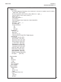
Emerson XMT-C Conductivity Two-Wire Transmitter Owner's manual
- Category
- Measuring, testing & control
- Type
- Owner's manual
This manual is also suitable for

Model Solu Comp
™
Xmt-C
Two-Wire Contacting Conductivity Transmitter
Instruction Manual
PN 51-Xmt-C/rev.E
January 2011

Emerson Process Management
2400 Barranca Parkway
Irvine, CA 92606 USA
Tel: (949) 757-8500
Fax: (949) 474-7250
http://www.raihome.com
© Rosemount Analytical Inc. 2011
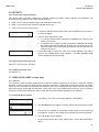
ESSENTIAL INSTRUCTIONS
READ THIS PAGE BEFORE PROCEEDING!
Rosemount Analytical designs, manufactures, and tests its products to meet many national and international
standards. Because these instruments are sophisticated technical products, you must properly install, use, and
maintain them to ensure they continue to operate within their normal specifications. The following instructions
must be adhered to and integrated into your safety program when installing, using, and maintaining Rosemount
Analytical products. Failure to follow the proper instructions may cause any one of the following situations to
occur: Loss of life; personal injury; property damage; damage to this instrument; and warranty invalidation.
• Read all instructions prior to installing, operating, and servicing the product. If this Instruction Manual is not the
correct manual, telephone 1-800-654-7768 and the requested manual will be provided. Save this Instruction
Manual for future reference.
• If you do not understand any of the instructions, contact your Rosemount representative for clarification.
• Follow all warnings, cautions, and instructions marked on and supplied with the product.
• Inform and educate your personnel in the proper installation, operation, and maintenance of the product.
• Install your equipment as specified in the Installation Instructions of the appropriate Instruction Manual and per
applicable local and national codes. Connect all products to the proper electrical and pressure sources.
• To ensure proper performance, use qualified personnel to install, operate, update, program, and maintain the
product.
• When replacement parts are required, ensure that qualified people use replacement parts specified by
Rosemount. Unauthorized parts and procedures can affect the product’s performance and place the safe
operation of your process at risk. Look alike substitutions may result in fire, electrical hazards, or improper
operation.
• Ensure that all equipment doors are closed and protective covers are in place, except when maintenance is
being performed by qualified persons, to prevent electrical shock and personal injury.
NOTICE
If a Model 375 Universal Hart
®
Communicator is used with these transmitters, the software within the Model 375 may require
modification. If a software modification is required, please contact your local Emerson Process Management Service Group
or National Response Center at 1-800-654-7768.
About This Document
This manual contains instructions for installation and operation of the Model Xmt-C Two-Wire
Contacting Conductivity Transmitter. The following list provides notes concerning all revisions of this
document.
Rev. Level Date Notes
A 3/05 This is the initial release of the product manual. The manual has been
reformatted to reflect the Emerson documentation style and updated to reflect
any changes in the product offering. This manual contains information on
HART Smart and F
OUNDATION Fieldbus versions of Model Solu Comp Xmt-C.
B 9/05 Add Foundation fieldbus agency approvals and FISCO version.
C 2/06 Revised section 1.0, page 1, and the case specification on page 2. Added new
drawings of FF and FI on section 4.0, pages 24-35.
D 12/10 Removed mention of patent, “Liquid Division” on address, and updated DNV logo.
E 1/11 Updated DWG no 9241581-00 pg 22 from rev A to rev B.

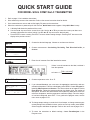
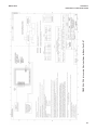
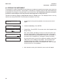
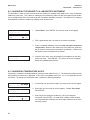
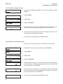
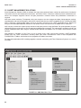
QUICK START GUIDE
FOR MODEL SOLU COMP Xmt-C TRANSMITTER
5. Choose the desired language. Choose >> to show more choices.
6. Choose measurement: Conductivity, Resistivity, Total Dissolved Solids, or
Custom.
7. Enter the cell constant. See label attached to sensor.
8. Choose temperature units: °C or °F.
9. If you selected Custom, you must enter the appropriate conductivity and con-
centration data points. From the main display, press MENU. Choose Program fol-
lowed by Measurement and Custom. The screen shown at left appears. Select
Enter Data Pts. Follow the prompts and enter the display units, the number of
data points, and enter the concentration and conductivity data points. Enter the
reference temperature and the temperature coefficient (slope). Once the analyz-
er has been configured, press EXIT. For a guide to the program menu, see the
menu trees on pages 5 & 6.
10. To change output settings, to scale the 4-20 mA output, to change measurement-
related settings from the default values, and to set security codes, press MENU.
Select Program and follow the prompts. Refer to the menu tree on pages 5 & 6.
11. To return the transmitter to default settings, choose ResetAnalyzer in the
Program menu.
Enter Data Pts
Ref Temp Slope
Cell Constant?
1.0000/cm
Temperature in?
° C ° F
Concentration
Units?
% ppm none
1. Refer to page 11 for installation instructions.
2. Wire conductivity sensor to the transmitter. Refer to the sensor instruction sheet for details.
3. Once connections are secure and verified, apply DC power to the transmitter.
4. When the transmitter is powered up for the first time, Quick Start screens appear. Using Quick Start is easy.
a. A blinking field shows the position of the cursor.
b. Use the t or u key to move the cursor left or right. Use the p or q key to move the cursor up or down or to
increase or decrease the value of a digit. Use the p or q key to move the decimal point.
c. Press ENTER to store a setting. Press EXIT to leave without storing changes. Pressing EXIT also returns the
display to the previous screen.
&
If there is no cell constant on the label, calculate it
from the equation:
cell const = K
500 + cal const
1000
e
j
Measure?
Cond
Resistivity >>
Measure?
TDS Custom >>
English
Français
Español >>


i
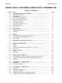
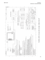
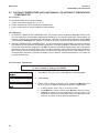
MODEL XMT-C TABLE OF CONTENTS
MODEL XMT-C TWO-WIRE CONDUCTIVITY TRANSMITTER
TABLE OF CONTENTS
Section Title Page
1.0 DESCRIPTION AND SPECIFICATIONS ................................................................ 1
1.1 Features and Applications........................................................................................ 1
1.2 Specifications........................................................................................................... 2
1.3 Hazardous Location Approval .................................................................................. 4
1.4 Menu Tree for Model XMT-C-HT.............................................................................. 5
1.5 Menu Tree for Model XMT-C-FF .............................................................................. 6
1.6 HART Communications............................................................................................ 7
1.7 FOUNDATION Fieldbus .............................................................................................. 7
1.8 Asset Management Solutions ................................................................................. 8
1.9 Ordering Information ............................................................................................... 10
1.10 Accessories ............................................................................................................. 10
2.0 INSTALLATION ....................................................................................................... 11
2.1 Unpacking and Inspection........................................................................................ 11
2.2 Installation................................................................................................................ 11
3.0 WIRING.................................................................................................................... 15
3.1 Power Supply / Current Loop — Model XMT-C-HT ................................................. 15
3.2 Power Supply Wiring for Model XMT-C-FF.............................................................. 16
3.2 Sensor Wiring .......................................................................................................... 17
4.0 INTRINSICALLY SAFE INSTALLATION................................................................. 18
5.0 DISPLAY AND OPERATION ................................................................................... 36
5.1 Display ..................................................................................................................... 36
5.2 Keypad..................................................................................................................... 36
5.3 Programming and Calibrating the Model Xmt — Tutorial......................................... 37
5.4 Menu Trees .............................................................................................................. 38
5.5 Diagnostic Messages............................................................................................... 38
5.6 Security .................................................................................................................... 41
5.7 Using Hold ............................................................................................................... 41
6.0 OPERATION WITH MODEL 375............................................................................. 42
6.1 Note on Model 375 HART and Foundation Fieldbus Communicator....................... 42
6.2 Connecting the HART and Foundation Fieldbus Communicator ............................. 42
6.3 Operation ................................................................................................................. 43
7.0 CALIBRATION — TEMPERATURE........................................................................ 47
7.1 Introduction .............................................................................................................. 47
7.2 Calibrating Temperature........................................................................................... 47
8.0 CALIBRATION — CONDUCTIVITY ....................................................................... 48
8.1 Introduction .............................................................................................................. 48
8.2 Entering the Cell Constant ....................................................................................... 49
8.3 Zeroing the Instrument............................................................................................. 50
8.4 Calibrating the Sensor in a Conductivity Standard................................................... 51
8.5 Calibrating the Sensor to a Laboratory Instrument .................................................. 52

MODEL XMT-C TABLE OF CONTENTS
TABLE OF CONTENTS CONT’D
ii
9.0 PROGRAMMING THE TRANSMITTER.................................................................. 53
9.1 General .................................................................................................................... 53
9.2 Changing Start-up Settings ...................................................................................... 53
9.3 Configuring and Ranging the Output ....................................................................... 54
9.4 Choosing and Configuring the Analytical Measurement .......................................... 57
9.5 Choosing Temperature Units & Manual or Automatic Temperature Compensation . 58
9.6 Setting a Security Code ........................................................................................... 59
9.7 Making HART-related Settings................................................................................. 60
9.8 Resetting Factory Calibration and Factory Default Settings .................................... 60
9.9 Selecting a Default Screen and Screen Contrast .................................................... 61
10.0 MAINTENANCE ...................................................................................................... 62
10.1 Overview .................................................................................................................. 62
10.2 Replacement Parts .................................................................................................. 62
11.0 THEORY OF OPERATION ...................................................................................... 63
11.1 Conductivity / Resistivity / % Concentration............................................................. 63
11.2 Temperature Correction ........................................................................................... 63
12.0 THEORY — REMOTE COMMUNICATIONS........................................................... 65
12.1 Overview of HART Communications........................................................................ 65
12.2 HART Interface Devices........................................................................................... 65
12.2 Asset Management Solutions .................................................................................. 66
13.0 RETURN OF MATERIAL......................................................................................... 67

MODEL XMT-C TABLE OF CONTENTS
LIST OF FIGURES
Number Title Page
1-1 Menu Tree — XMT-C-HT ......................................................................................... 5
1-2 Menu Tree — XMT-C-FF.......................................................................................... 6
1-3 Configuring Model XMT Transmitter with FOUNDATION Fieldbus .............................. 7
1-4 HART and FOUNDATION Fieldbus Communicators ................................................... 8
1-5 AMS Main Menu Tools ............................................................................................. 9
2-1 Removing the Knockouts ......................................................................................... 11
2-2 Power Supply / Current Loop Wiring ........................................................................ 11
2-3 Panel Mount Installation ........................................................................................... 12
2-4 Pipe Mount Installation ............................................................................................. 13
2-5 Surface Mount Installation........................................................................................ 14
3-1 Load/Power Supply Requirements........................................................................... 15
3-2 Power Supply / Current Loop Wiring ........................................................................ 15
3-3 Typical Fieldbus Network Electrical Wiring Configuration ........................................ 16
3-4 Loop Power and Sensor Wiring................................................................................ 16
4-1 FM Intrinsically Safe Label for Model XMT-C-HT ..................................................... 18
4-2 FM Intrinsically Safe Installation for Model XMT-C-HT............................................. 19
4-3 CSA Intrinsically Safe Label for Model XMT-C-HT ................................................... 20
4-4 CSA Intrinsically Safe Installation for Model XMT-C-HT........................................... 21
4-5 ATEX Intrinsically Safe Label for Model XMT-C-HT ................................................. 22
4-6 ATEX Intrinsically Safe Installation for Model XMT-C-HT......................................... 23
4-7 FM Intrinsically Safe Label for Model XMT-C-FF ..................................................... 24
4-8 FM Intrinsically Safe Installation for Model XMT-C-FF ............................................. 25
4-9 CSA Intrinsically Safe Label for Model XMT-C-FF ................................................... 26
4-10 CSA Intrinsically Safe Installation for Model XMT-C-FF ........................................... 27
4-11 ATEX Intrinsically Safe Label for Model XMT-C-FF ................................................. 28
4-12 ATEX Intrinsically Safe Installation for Model XMT-C-FF ......................................... 29
4-13 FM Intrinsically Safe Label for Model XMT-C-FI....................................................... 30
4-14 FM Intrinsically Safe Installation for Model XMT-C-FI .............................................. 31
4-15 CSA Intrinsically Safe Label for Model XMT-C-FI..................................................... 32
4-16 CSA Intrinsically Safe Installation for Model XMT-C-FI ............................................ 33
4-17 ATEX Intrinsically Safe Label for Model XMT-C-FI................................................... 34
4-18 ATEX Intrinsically Safe Installation for Model XMT-C-FI .......................................... 35
5-1 Displays During Normal Operation........................................................................... 36
5-2 Solu Comp Xmt Keypad ........................................................................................... 36
5-3 Menu Tree for Model XMT-C-HT .............................................................................. 39
5-4 Menu Tree for Model XMT-C-FF .............................................................................. 40
6-1 Connecting the Model 375 Communicator .............................................................. 42
6-2 XMT-C-HT HART / Model 375 Menu Tree................................................................ 44
12-1 HART Communicators ............................................................................................. 65
12-2 AMS Main Menu Tools ............................................................................................. 66


1
MODEL XMT-C SECTION 1.0
DESCRIPTION AND SPECIFICATIONS
SECTION 1.0
DESCRIPTION AND SPECIFICATIONS
Model Xmt Family of Two-wire Transmitters
• CHOICE OF COMMUNICATION PROTOCOLS:
HART
®
or FOUNDATION
®
Fieldbus
• CLEAR, EASY-TO-READ two-line display shows commissioning menus
and process measurement displays in English
• SIMPLE TO USE MENU STRUCTURE
• CHOICE OF PANEL OR PIPE/SURFACE MOUNTING
• NON-VOLATILE MEMORY retains program settings and calibration
data during power failures
• SIX LOCAL LANGUAGES - English, French, German, Italian, Spanish and Portuguese
1.1 FEATURES AND APPLICATIONS
The Solu Comp Model Xmt family of transmitters can be
used to measure pH, ORP, conductivity (using either con-
tacting or toroidal sensors), resistivity, oxygen (ppm and
ppb level), free chlorine, total chlorine, monochloramine
and ozone in a variety of process liquids. The Xmt is com-
patible with most Rosemount Analytical sensors. See the
Specification sections for details.
The transmitter has a rugged, weatherproof, corrosion-
resistant enclosure (NEMA 4X and IP65). The panel mount
version fits standard ½ DIN panel cutouts, and its shallow
depth is ideally suited for easy mounting in cabinet-type
enclosures. A panel mount gasket is included to maintain
the weather rating of the panel. Surface/pipe mount enclo-
sure includes self-tapping screws for surface mounting. A
pipe mounting accessory kit is available for mounting to a
2-inch pipe.
The transmitter has a two-line 16-character display. Menu
screens for calibrating and registering choices are simple
and intuitive. Plain language prompts guide the user
through the procedures. There are no service codes to
enter before gaining access to menus.
Two digital communication protocols are available: HART
(model option -HT) and F
OUNDATION fieldbus (model option
-FF or -FI). Digital communications allow access to AMS
(Asset Management Solutions). Use AMS to set up and
configure the transmitter, read process variables, and trou-
bleshoot problems from a personal computer or host any-
where in the plant.
The seven-button membrane-type keypad allows local pro-
gramming and calibrating of the transmitter. The HART
Model 375 communicator can also be used for program-
ming and calibrating the transmitter.
The Model Xmt-C Transmitter with the appropriate sensor
measures dissolved oxygen (ppm and ppb level), free
chlorine, total chlorine, monochloramine, and ozone in
water and aqueous solutions. The transmitter is compati-
ble with Rosemount Analytical 499A amperometric sen-
sors for oxygen, chlorine, monochloramine, and ozone;
and with Hx438, Bx438, and Gx448 steam-sterilizable oxy-
gen sensors.
For free chlorine measurements, both automatic and man-
ual pH correction are available. pH correction is necessary
because amperometric free chlorine sensors respond only
to hypochlorous acid, not free chlorine, which is the sum of
hypochlorous acid and hypochlorite ion. To measure free
chlorine, most competing instruments require an acidified
sample. Acid lowers the pH and converts hypochlorite ion
to hypochlorous acid. The Model Xmt-C eliminates the
need for messy and expensive sample conditioning by
measuring the sample pH and using it to correct the chlo-
rine sensor signal. If the pH is relatively constant, a fixed
pH correction can be used, and the pH measurement is
not necessary. If the pH is greater than 7.0 and fluctuates
more than about 0.2 units, continuous measurement of pH
and automatic pH correction is necessary. See
Specifications section for recommended pH sensors.
Corrections are valid to pH 9.5.
The transmitter fully compensates oxygen, ozone, free
chlorine, total chlorine, and monochloramine readings for
changes in membrane permeability caused by tempera-
ture changes.
For pH measurements — pH is available with free chlorine
only — the Xmt-C features automatic buffer recognition
and stabilization check. Buffer pH and temperature data
for commonly used buffers are stored in the transmitter.
Glass impedance diagnostics warn the user of an aging or
failed pH sensor.

2
MODEL XMT-C SECTION 1.0
DESCRIPTION AND SPECIFICATIONS
1.2 SPECIFICATIONS
1.2.1 GENERAL SPECIFICATIONS
Case: ABS (panel mount), polycarbonate (pipe/wall mount);
NEMA 4X/CSA 4 (IP65)
Dimensions
Panel (code -10): 6.10 x 6.10 x 3.72 in. (155 x
155 x 94.5 mm)
Surface/Pipe (code -11): 6.23 x 6.23 x 3.23 in. (158
x 158 x 82 mm); see page 15 for dimensions of pipe
mounting bracket.
Conduit openings: Accepts PG13.5 or 1/2 in. conduit fit-
tings
Ambient Temperature: 32 to 122°F (0 to 50°C). Some
degradation of display above 50°C.
Storage Temperature: -4 to 158°F (-20 to 70°C)
Relative Humidity: 10 to 90% (non-condensing)
Weight/Shipping Weight: 2 lb/3 lb (1 kg/1.5 kg)
Display: Two line, 16-character display. Character height:
4.8 mm; first line shows process variable, second line
shows process temperature and output current. Fault
and warning messages, when triggered, alternate with
temperature and output readings.
During calibration and programming, messages,
prompts, and editable values appear on the two-line
display.
Temperature resolution: 0.1°C (≤99.9°C);
1°C (≥100°C)
Hazardous Location Approval: For details, see specifi-
cations for the measurement of interest.
RFI/EMI: EN-61326
DIGITAL COMMUNICATIONS:
HART —
Power & Load Requirements: Supply voltage at the
transmitter terminals should be at least 12 Vdc.
Power supply voltage should cover the voltage
drop on the cable plus the external load resistor
required for HART communications (250 Ω mini-
mum). Minimum power supply voltage is 12 Vdc.
Maximum power supply voltage is 42.4 Vdc. The
graph shows the supply voltage required to
maintain 12 Vdc (upper line) and 30 Vdc (lower
line) at the transmitter terminals when the cur-
rent is 22 mA.
Analog Output: Two-wire, 4-20 mA output with
superimposed HART digital signal. Fully scalable
over the operating range of the sensor.
Output accuracy: ±0.05 mA
F
OUNDATION fieldbus —
Power & Load Requirements: A power supply volt-
age of 9-32 Vdc at 13 mA is required.
Fieldbus Intrinsically Safe COncept/FISCO-compliant
versions of Model Xmt Foundation Fieldbus trans-
mitters are available.
Solu Comp is a trademark of Rosemount Analytical.
Xmt is a trademark of Rosemount Analytical.
HART is a registered trademark of the HART Communication Foundation.
FOUNDATION is a registered trademark of Fieldbus Foundation.

MODEL XMT-C SECTION 1.0
DESCRIPTION AND SPECIFICATIONS
3
1.2.2 FUNCTIONAL SPECIFICATIONS
Automatic Temperature Compensation:
3-wire Pt 100 or Pt 1000 RTD
Conductivity: 0 to 200°C (32 to 392°F)
Resistivity: 0 to 100°C (32 to 212°F)
Low Conductivity: 0 to 100°C (32 to 212°F)
Diagnostics: The internal diagnostics can detect:
Calibration Error ROM Failure
Temperature Slope Error Zero Error
High Temperature Warning CPU Failure
Low Temperature Warning Input Warning
Once one of the above is diagnosed, the Xmt-C will
display a message describing the problem.
Digital Communications:
HART: PV, SV, and TV assignable to measurement
(conductivity, resistivity, or concentration), tempera-
ture, and raw conductivity. Raw conductivity is meas-
ured conductivity before temperature correction.
Fieldbus: Three AI blocks assignable to measurement
(conductivity, resistivity, or concentration), tempera-
ture, and raw conductivity. Raw conductivity is meas-
ured conductivity before temperature correction.
Execution time 75 msec. One PID block; execution
time 150 msec. Device type: 4084. Device revision: 1.
Certified to ITK 4.5.
1.2.3 TRANSMITTER SPECIFICATIONS @ 25°C
Measured Range: 0-20,000 µS/cm
Accuracy: ± 0.7% of reading and ± 0.002 µS/cm
Repeatability: ± 0.25% of reading
Temperature Accuracy: ± 0.2°C between 0 and 50°C;
± 0.5°C above 50°C (excludes inaccuracies in sensor)
Temperature Compensation: Slope 0-5%/°C, ultra-pure
water, cation conductivity, or raw (uncompensated)
conductivity.
Compatible RTD: 100Ω or 1000Ω with automatic recogni-
tion
Ambient Temperature Coefficient:
± 0.05% of reading/°C
Maximum Cable Length: 200 ft (61 m)
1.2.4 LOOP SPECIFICATIONS
Accuracy: under controlled laboratory conditions at 25°C
(77°F) with perfectly calibrated ENDURANCE sensor of
appropriate cell constant:
Calibration: Calibrate against previously calibrated stan-
dard sensor and analyzer, or calibrate against solution
of known conductivity.
1.2.5 SENSOR SELECTION GUIDELINES
Note: The conductivity values shown in the above chart are for
UNCOMPENSATED (or RAW) conductivity at 25°C.
Maximum range values will vary due to temperature compen-
sation selection, process temperature, and other process
conditions.
RECOMMENDED SENSORS:
Model 140 Retractable Conductivity
Model 141 Insertion High Conductivity
Model 142 Insertion Low Conductivity
Model 150 Insertion/Submersion Conductivity
Model 400/VP Screw-In Low Conductivity
Model 401 Screw-In High Conductivity
Model 402/VP Retractable Conductivity
Model 403/VP Sanitary Conductivity
Model 404 Low Flow Conductivity
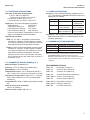
Cell Constant Range Loop accuracy
0.01/cm up to 50 µS/cm ±0.7% of reading
±0.002 µS/cm
0.1/cm 0.4 to 50 µS/cm ±0.7% of reading
50 to 200 µS/cm ±2% of reading
1.0/cm 4 to 5000 µS/cm ±0.7% of reading
5000 to 20,000 µS/cm ±2% of reading
Cell Constant Suggested Conductivity Range
0.01/cm up to 50 µS/cm
0.1/cm 0.4 to 500 µS/cm
1.0/cm 4 to 20,000 µS/cm

4
MODEL XMT-C SECTION 1.0
DESCRIPTION AND SPECIFICATIONS
1.3 HAZARDOUS LOCATION APPROVALS
Intrinsic Safety:
Class I, II, III, Div. 1
Groups A-G
T4 Tamb = 50°C
Class I, II, III, Div. 1
Groups A-G
T4 Tamb = 50°C
ATEX 1180
II 1 G
Baseefa04ATEX0214X
EEx ia IIC T4
Tamb = 0°C to 50°C
Non-Incendive:
Class I, Div. 2, Groups A-D
Dust Ignition Proof
Class II & III, Div. 1, Groups E-G
NEMA 4/4X Enclosure
Class I, Div. 2, Groups A-D
Dust Ignition Proof
Class II & III, Div. 1, Groups E-G
NEMA 4/4X Enclosure
T4 Tamb = 50°C

MODEL XMT-C SECTION 1.0
DESCRIPTION AND SPECIFICATIONS
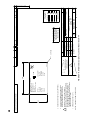
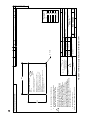
FIGURE 1-1. MENU TREE FOR MODEL SOLU COMP XMT-C-HT TRANSMITTER
1.4 MENU TREE FOR MODEL XMT-C-HT
5
Language

MODEL XMT-C SECTION 1.0
DESCRIPTION AND SPECIFICATIONS
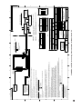
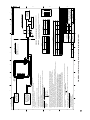
FIGURE 1-2. MENU TREE FOR MODEL SOLU COMP XMT-C-FF TRANSMITTER
1.5 MENU TREE FOR MODEL XMT-C-FF
6
Language

7
MODEL XMT-C SECTION 1.0
DESCRIPTION AND SPECIFICATIONS
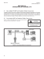
1.7 FOUNDATION FIELDBUS
Figure 1-3 shows a Xmt-C-FF being used to measure conductivity. The figure also shows three ways in which Fieldbus
communication can be used to read process variables and configure the transmitter.
FIGURE 1-3. CONFIGURING MODEL XMT-C TRANSMITTER WITH FOUNDATION FIELDBUS
1.6 HART COMMUNICATIONS
1.6.1 OVERVIEW OF HART COMMUNICATION
HART (highway addressable remote transducer) is a digital communication system in which two frequencies are superim-
posed on the 4 to 20 mA output signal from the transmitter. A 1200 Hz sine wave represents the digit 1, and a 2400 Hz
sine wave represents the digit 0. Because the average value of a sine wave is zero, the digital signal adds no dc compo-
nent to the analog signal. HART permits digital communication while retaining the analog signal for process control.
The HART protocol, originally developed by Fisher-Rosemount, is now overseen by the independent HART
Communication Foundation. The Foundation ensures that all HART devices can communicate with one another. For more
information about HART communications, call the HART Communication Foundation at (512) 794-0369. The internet
address is http://www.hartcomm.org.
1.6.2 HART INTERFACE DEVICES
The Model 375 HART Communicator is a hand-held device that provides a common link to all HART SMART instru-
ments and allows access to AMS (Asset Management Solutions). Use the HART communicator to set up and control the
XMT-C-HT and to read measured variables. Press ON to display the on-line menu. All setup menus are available
through this menu.
HART communicators allow the user to view measurement data (conductivity, TDS, resistivity, and temperature), program
the transmitter, and download information from the transmitter for transfer to a computer for analysis. Downloaded informa-
tion can also be sent to another HART transmitter. Either a hand-held communicator, such as the Rosemount Model 375, or
a computer can be used. HART interface devices operate from any wiring termination point in the 4 - 20 mA loop. A mini-
mum load of 250 ohms must be present between the transmitter and the power supply. See Figure 1-4.
If your communicator does not recognize the Model XMT-C transmitter, the device description library may need updating.
Call the manufacturer of your HART communication device for updates.
XMT-C-FF
conductivity
HCl

8
MODEL XMT-C SECTION 1.0
DESCRIPTION AND SPECIFICATIONS
FIGURE 1-4. HART and FOUNDATION™ Fieldbus Communicators.
Both the Rosemount Model 375 (or 275) and a computer can be used to communicate with a HART transmitter. The 250 ohm load
(minimum) must be present between the transmitter and the power supply.
1.8 ASSET MANAGEMENT SOLUTIONS
Asset Management Solutions (AMS) is software that helps plant personnel better monitor the performance of analytical
instruments, pressure and temperature transmitters, and control valves. Continuous monitoring means maintenance per-
sonnel can anticipate equipment failures and plan preventative measures before costly breakdown maintenance is
required.
AMS uses remote monitoring. The operator, sitting at a computer, can view measurement data, change program settings,
read diagnostic and warning messages, and retrieve historical data from any HART-compatible device, including the Model
XMT-C transmitter. Although AMS allows access to the basic functions of any HART compatible device, Rosemount
Analytical has developed additional software for that allows access to all features of the Model Xmt-C transmitter.
AMS can play a central role in plant quality assurance and quality control. Using AMS Audit Trail, plant operators can track
calibration frequency and results as well as warnings and diagnostic messages. The information is available to Audit Trail
whether calibrations were done using the infrared remote transmitter, the Model 375 HART communicator, or AMS soft-
ware.
AMS operates in Windows 2000, NT, and XP operating systems. See Figure 1-5 for a sample screen. AMS communicates
through a HART-compatible modem with any HART transmitters, including those from other manufacturers. AMS is also
compatible with FOUNDATION Fieldbus, which allows future upgrades to Fieldbus instruments.
Rosemount Analytical AMS windows provide access to all transmitter measurement and configuration variables. The
user can read raw data, final data, and program settings and can reconfigure the transmitter from anywhere in the plant.
Model XMT-C

MODEL XMT-C SECTION 1.0
DESCRIPTION AND SPECIFICATIONS
FIGURE 1-5. AMS MAIN MENU TOOLS
9

10
MODEL XMT-C SECTION 1.0
DESCRIPTION AND SPECIFICATIONS
1.10 ACCESSORIES
POWER SUPPLY: Use the Model 515 Power Supply to provide dc loop power to the transmitter. The Model 515 pro-
vides two isolated sources at 24Vdc and 200 mA each. For more information refer to product data sheet 71-515.
ALARM MODULE: The Model 230A alarm Module receives the 4-20 mA signal from the XMT-C-HT transmitter and acti-
vates two alarm relays. High/high, low/low, and high/low are available. Hysteresis (deadband) is also adjustable. For
more information, refer to product data sheet 71-230A.
HART COMMUNICATOR: The Model 375 HART communicator allows the user to view measurement values as well as
to program and configure the transmitter. The Model 375 attaches to any wiring terminal across the output loop. A
minimum 250 Ω load must be between the power supply and transmitter. Order the Model 375 communicator from
Emerson Process Management. Call (800) 999-9307.
1.9 ORDERING INFORMATION
The Solu Comp Model Xmt Two-Wire Transmitter is intended for conductivity and resistivity measurements using con-
tacting conductivity sensors.
ACCESSORIES
MODEL/PN DESCRIPTION
515 DC loop power supply (see product data sheet 71-515)
230A Alarm module (see product data sheet 71-230A)
23820-00 2-in. pipe mounting kit
9240048-00 Stainless steel tag, specify marking
23554-00 Gland fittings PG 13.5, 5 per package
CODE REQUIRED SELECTION
HT Analog 4-20 mA output with superimposed HART digital signal
FF Foundation fieldbus digital output
FI Foundation fieldbus digital output with FISCO
CODE REQUIRED SELECTION
10 Panel mounting enclosure
11 Pipe/Surface mounting enclosure (pipe mounting requires accessory kit PN 23820-00)
CODE AGENCY APPROVALS
60 No approval
67 FM approved intrinsically safe and non-incendive (when used with appropriate sensor and safety barrier)
69 CSA approved intrinsically safe and non-incendive (when used with appropriate sensor and safety barrier)
73 ATEX approved intrinsically safe (when used with appropriate sensor and safety barrier)
CODE REQUIRED SELECTION
P pH/ORP
MODEL
Xmt SMART TWO-WIRE MICROPROCESSOR TRANSMITTER
Xmt-P-HT-10-67 EXAMPLE

11
MODEL XMT-C SECTION 2.0
INSTALLATION
SECTION 2.0
INSTALLATION
2.1 Unpacking and Inspection
2.2 Installation
2.1 UNPACKING AND INSPECTION
Inspect the shipping container. If it is damaged, contact the shipper immedi-
ately for instructions. Save the box. If there is no apparent damage, remove
the transmitter. Be sure all items shown on the packing list are present. If
items are missing, immediately notify Rosemount Analytical.
Save the shipping container and packaging. They can be reused if it is later
necessary to return the transmitter to the factory.
2.2 INSTALLATION
1. Although the transmitter is suitable for outdoor use, do not install it in
direct sunlight or in areas of extreme temperatures.
2. Install the transmitter in an area where vibrations and electromagnetic
and radio frequency interference are minimized or absent.
3. Keep the transmitter and sensor wiring at least one
foot from high voltage conductors. Be sure there is
easy access to the transmitter.
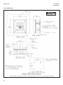
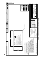
4. The transmitter is suitable for panel (Figure 2-3), pipe
(Figure 2-4), or surface (Figure 2-5) mounting.
5. The transmitter case has two 1/2-inch (PG13.5) con-
duit openings and either three or four 1/2-inch knock-
outs. The panel mount XMT-C-HT has four knockouts.
The pipe/surface mount transmitter has three knock-
outs*. One conduit opening is for the power/output
cable; the other opening is for the sensor cable.
Figure 1 shows how to remove a knockout. The knock-
out grooves are on the outside of the case. Place the
screwdriver blade on the inside of the case and align it
approximately along the groove. Rap the screwdriver
sharply with a hammer until the groove cracks. Move
the screwdriver to an uncracked portion of the groove
and continue the process until the knockout falls out.
Use a small knife to remove the flash from the inside
of the hole.
6. Use weathertight cable glands to keep moisture out to
the transmitter. If conduit is used, plug and seal the
connections at the transmitter housing to prevent
moisture from getting inside the instrument.
7. To reduce the likelihood of stress on wiring connec-
tions, do not remove the hinged front panel (-11 mod-
els) from the base during wiring installation. Allow suf-
ficient wire leads to avoid stress on conductors.
*NEMA plug may be supplied instead of knockout for
pipe/surface version.
FIGURE 2-1. Removing the Knockouts
FIGURE 2-2. Power Supply/Current Loop Wiring

12
MODEL XMT-C SECTION 2.0
INSTALLATION
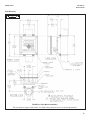
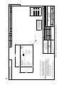
FIGURE 2-3. Panel Mount Installation
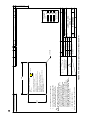
Access to the wiring terminals is through the rear cover. Four screws hold the cover in place.
Panel Mounting.
MILLIMETER
INCH
Page is loading ...
Page is loading ...
Page is loading ...
Page is loading ...
Page is loading ...
Page is loading ...
Page is loading ...
Page is loading ...
Page is loading ...
Page is loading ...
Page is loading ...
Page is loading ...
Page is loading ...
Page is loading ...
Page is loading ...
Page is loading ...
Page is loading ...
Page is loading ...
Page is loading ...
Page is loading ...
Page is loading ...
Page is loading ...
Page is loading ...
Page is loading ...
Page is loading ...
Page is loading ...
Page is loading ...
Page is loading ...
Page is loading ...
Page is loading ...
Page is loading ...
Page is loading ...
Page is loading ...
Page is loading ...
Page is loading ...
Page is loading ...
Page is loading ...
Page is loading ...
Page is loading ...
Page is loading ...
Page is loading ...
Page is loading ...
Page is loading ...
Page is loading ...
Page is loading ...
Page is loading ...
Page is loading ...
Page is loading ...
Page is loading ...
Page is loading ...
Page is loading ...
Page is loading ...
Page is loading ...
Page is loading ...
Page is loading ...
Page is loading ...
Page is loading ...
Page is loading ...
-
 1
1
-
 2
2
-
 3
3
-
 4
4
-
 5
5
-
 6
6
-
 7
7
-
 8
8
-
 9
9
-
 10
10
-
 11
11
-
 12
12
-
 13
13
-
 14
14
-
 15
15
-
 16
16
-
 17
17
-
 18
18
-
 19
19
-
 20
20
-
 21
21
-
 22
22
-
 23
23
-
 24
24
-
 25
25
-
 26
26
-
 27
27
-
 28
28
-
 29
29
-
 30
30
-
 31
31
-
 32
32
-
 33
33
-
 34
34
-
 35
35
-
 36
36
-
 37
37
-
 38
38
-
 39
39
-
 40
40
-
 41
41
-
 42
42
-
 43
43
-
 44
44
-
 45
45
-
 46
46
-
 47
47
-
 48
48
-
 49
49
-
 50
50
-
 51
51
-
 52
52
-
 53
53
-
 54
54
-
 55
55
-
 56
56
-
 57
57
-
 58
58
-
 59
59
-
 60
60
-
 61
61
-
 62
62
-
 63
63
-
 64
64
-
 65
65
-
 66
66
-
 67
67
-
 68
68
-
 69
69
-
 70
70
-
 71
71
-
 72
72
-
 73
73
-
 74
74
-
 75
75
-
 76
76
-
 77
77
-
 78
78


Emerson XMT-C Conductivity Two-Wire Transmitter Owner's manual
- Category
- Measuring, testing & control
- Type
- Owner's manual
- This manual is also suitable for
Ask a question and I''ll find the answer in the document
Finding information in a document is now easier with AI
Related papers
-
Rosemount XMT-P pH Two-Wire Analyzer Transmitter Owner's manual
-
-
Emerson XMT-P-FF/FI User manual
-
-
-
AMS 375 Quick start guide
-
-
-
-
Emerson DLC3020f User manual
Other documents
-
-
-
-
-
-
-
 HART HPHV50 Owner's manual
-
-
-
