Uninterruptible Power Supply
EVO DSP TM
10-30kVA
User’s manual


UPS EVO DSP TM 1 User’s manual
Important Notice
Thank you for purchasing TECNOWARE UPS.
This document provides instructions about safety, installation and handling of the UPS. It is necessary
to read the manual completely before working on this equipment.
Read the manual completely before working on this equipment!
Keep this manual near UPS for easy consultation!
Symbols
This symbol points out the instructions which are especially important.
This symbol points out the risk of electric shock if the following instruction is not
obeyed.
This symbol points out the instructions, which may result in injury to the
operator or damage to the equipment if not obeyed.
© Copyright 2009 TECNOWARE s.r.l. All rights reserved.
All trademarks are property of their respective owners.
TECNOWARE s.r.l.
www.service.tecnoware.com
This manual has been printed and edited by TECNOWARE s.r.l.
June 2009 edition - version 1.4

User’s manual 2 UPS EVO DSP TM
Index
1 Safety .......................................................................................................... 4
2 Installation .................................................................................................... 5
2.1 Transportation ............................................................................................. 5
2.2 Unpacking................................................................................................... 5
2.3 Storage...................................................................................................... 5
2.4 Location and Connection of the UPS ................................................................... 5
2.4.1 Environmental Requisites........................................................................................5
2.4.2 Electrical Requisites ..............................................................................................6
2.5 Connections ................................................................................................ 7
2.5.1 Internal Battery Connection.....................................................................................8
2.5.2 Power Connections................................................................................................9
2.5.2.1 Protective Earth (Ground) Connections.............................................................9
2.5.2.2 Input Connection .......................................................................................9
2.5.2.3 Separated Bypass Mains Input Connection (Optional) .......................................... 10
2.5.2.4 External Battery Connection .......................................................................10
2.5.2.5 Output Connection................................................................................... 10
2.5.3 Communication Interfaces Connections .....................................................................10
3 Operating Modes ............................................................................................11
3.1 Bypass Mode...............................................................................................12
3.2 Normal Mode ..............................................................................................13
3.3 Battery Mode..............................................................................................13
4 Control and Monitoring ....................................................................................14
4.1 Front Panel................................................................................................14
4.1.1 Keypad............................................................................................................ 14
4.1.2 Mimic Panel ......................................................................................................15
4.1.3 Liquid Crystal Display (LCD) and User Menu................................................................. 16
4.1.4 Buzzer............................................................................................................. 19
5 Operating Procedures......................................................................................20
5.1 Commissioning ............................................................................................20
5.2 Decommissioning .........................................................................................20
5.3 Switching into Manual Bypass during Operation.....................................................21
5.4 Returning from Manual Bypass to UPS.................................................................21
5.5 Connection to a Generator..............................................................................21
6 Operating Procedures for Parallel System.............................................................22
6.1 Introduction ...............................................................................................22
6.2 Procedure for Commissioning and Start Up (First Installation) ...................................22
6.3 Procedure for Transferring to Static Bypass .........................................................25
6.4 Procedure for Transferring to (Maintenance) Manual Bypass......................................25
6.5 Procedure for Switching OFF ...........................................................................25
7 Features and Operating Limits...........................................................................26
7.1 Mains Limits for Normal mode..........................................................................26
7.2 Bypass Mains Limits for Bypass mode..................................................................26
7.3 Battery Test...............................................................................................26
7.4 Overload Behavior........................................................................................27
7.5 Electronic Short Circuit Protection....................................................................27

UPS EVO DSP TM 3 User’s manual
8
Communication Interfaces ............................................................................... 28
8.1 RS232 Communication ...................................................................................28
8.2 RS422 Communication ...................................................................................28
8.3 Digital Inputs (UPS OFF and GEN ON)..................................................................29
8.4 Free Contact Communication...........................................................................29
9 Maintenance ................................................................................................ 30
9.1 Battery Fuses..............................................................................................30
9.2 Battery .....................................................................................................30
9.3 Fans.........................................................................................................30
9.4 Capacitors .................................................................................................30
10 Troubleshooting............................................................................................ 31
11 Technical Specifications.................................................................................. 34
12 Internal Battery Location - Connection Instructions ............................................... 36
13 Internal Battery Location - Connection Diagram .................................................... 37

User’s manual 4 UPS EVO DSP TM
1 Safety
Information related to the safety of the UPS, loads and the user is summarized
below. But the equipment should not be installed before reading this manual
completely.
The equipment may only be installed and commissioned by authorized technical persons.
When the UPS is brought from a cold place to a warmer place, humidity in the air may cause
condensation in the UPS. In this case, allow UPS to stand for two hours in the warmer place
before beginning with the installation.
Even if no connection has been done, hazardous voltages may exist on connection terminals
and inside the UPS. Do not touch these parts.
Connect the PE (Earth) ground connector before connecting any other cable.
Do not put the Battery fuses into the fuse holder before operating the equipment and seeing
the “NORMAL” message on the LCD.
The connections shall be made with cables of appropriate cross-section in order to prevent the
risk of fire. All cables shall be of insulated flexible type (tri-rated) and shall not be laid out on
the walk path of persons. Cables crossing a path must be protected in accordance with local
electrical and safety regulations.
Do not expose UPS to rain or liquids in general. Do not put any solid objects into any
access/vent hole or space.
The equipment shall be operated in an environment, which is specified in “Location and
Connection of the UPS” section of this manual.
Affix a label bearing the following expression, on the distribution panels feeding the UPS:
“Isolate the Uninterruptible Power Supply (UPS) before working on this circuit”.
Do not plug the communication cables in or out during lightening or electrical storms.
The equipment shall only be maintained and fixed by authorized technical persons.
In case of a fault situation (damaged cabinet or connections, penetration of foreign materials
into the cabinet etc.) de-energize the UPS immediately and consult with Tecnoware Technical
Service.
Used/dead batteries must be disposed of at an authorized waste disposal centre – local
regulations may apply – batteries must not be put in a land fill.
Keep this manual nearby the UPS for easy consultation.
The equipment shall be packed properly during transportation.
The equipment is compliant with the European Community directives. Hence it is marked:

UPS EVO DSP TM 5 User’s manual
2 Installation
2.1 Transportation
The UPS must remain in a vertical position throughout the transportation. Make sure that the floor can
support the weight of the system – check with building engineer if not sure.
2.2 Unpacking
Equipment and batteries whose packaging is damaged during transportation shall be
inspected by a qualified technical person before starting with the installation.
The procedure is as follows:
Remove the bands and the protective packaging from the UPS.
Use suitable equipment to remove the UPS from the pallet.
The equipment shall be packed properly during transportation. Therefore it is
recommended to keep the original package for future needs (e.g. further transportation
or return to Service Department).
Check if the following are provided with the equipment:
Key of the cabinet door
Battery fuses (three pieces)
Test report
2.3 Storage
Recommended storage temperature, humidity and altitude values are listed in the “Technical
Specifications” section.
If the batteries will be stored for longer than 2 months, they must be charged periodically. Charge
period depends on the storage temperature. The relationship is as shown below:
Every 9 months if the temperature is below 20°C.
Every 6 months if the temperature is between 20°C and 30°C.
Every 3 months if the temperature is between 30°C and 40°C.
Every 2 months if the temperature is over 40°C.
2.4 Location and Connection of the UPS
2.4.1 Environmental Requisites
This product meets the safety requirements for devices to be operated in restricted access locations
according to EN 60950-1 safety standard, which states that the owner should guarantee the following:
Access to the equipment can only be gained by service persons or by users who have been
instructed about the reasons for the restrictions applied to the location and about any
precautions that shall be taken.

User’s manual 6 UPS EVO DSP TM
Access is through the use of a tool or lock and key, or other means of security and is controlled
by the authorized person responsible for the location.
Recommended operating temperature, humidity and altitude values are listed on the “Technical
Specifications” section. Air conditioning may be required to provide these values.
Other requisites are:
The equipment and the batteries shall not be exposed to direct sunlight or placed near to a
heat source.
Do not expose UPS to rain or any liquids in general. Do not introduce any solid objects.
Avoid dusty environments or areas where dust of conductive or corrosive materials is present.
Air outlets of the UPS are on sides, front and back. Leave at least 75 cm at the front and both
sides and 50 cm at the back for maintenance and ventilation.
2.4.2 Electrical Requisites
The installation must comply with local national installation regulations.
The electrical distribution panels for the mains and separate Bypass mains inputs must have a
protection and disconnection system. Disconnection devices used in these panels shall disconnect all
line conductors and the neutral conductor simultaneously. The following table shows the recommended
size of the mains and separate Bypass mains input protection devices (thermal, magnetic and
differential) and the cable cross-sections for the linear loads.
UPS
Rating
Input
thermal
protection
Bypass mains
input
thermal
protection
Input cable
cross-section
Bypass mains
input cable
cross-section
Battery cable
cross-section
Neutral
Cable Cross
section
Leakage
current
protection*
10 kVA 25 A 50 A 6 mm
2
10 mm
2
6 mm
2
10 mm
2
30 mA
15 kVA 25 A 80 A 6 mm
2
10 mm
2
6 mm
2
10 mm
2
30 mA
20 kVA 40 A 100 A 10 mm
2
25 mm
2
10 mm
2
16 mm
2
30 mA
30 kVA 63 A 160 A 16 mm
2
35 mm
2
16 mm
2
35 mm
2
30 mA
Input magnetic protection devices shall have D characteristic.
*Load leakage currents are added to those generated by the UPS. If loads with high leakage currents
are present, adjust this value accordingly. It is recommended to adjust the protective device after
measuring the total leakage current with the UPS installed and operational with the intended load.
During transitory phases (power failure, return and voltage fluctuations) short leakage current peaks
may occur. Make sure that the protection is not activated in such cases.
If the loads have a nonlinear characteristic, the current on the mains input, separate
Bypass mains input may have a value that is 1.5-2 times the current phase value during
operation. In this case, size the neutral cables and the input/output protection
accordingly.

UPS EVO DSP TM 7 User’s manual
According to EN 62040-1-2, the user shall place a warning label on the input distribution
panel and the other primary power isolators, in order to prevent the risk of electric
shock caused by a fault voltage on the UPS. The label shall carry the following wording:
ISOLATE THE UNINTERRUPTIBLE POWER SUPPLY (UPS) BEFORE WORKING ON THIS CIRCUIT
2.5 Connections
Connections shall be done by authorized technical staff only.
When the UPS is brought from a cold place to a warmer place, humidity of the air may
condensate in it. In this case, wait for two hours before beginning with the installation.
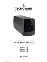
UPS front side
The layout of the Communication Interface board, Parallel board, slot
for SNMP Interface, circuit breakers and connection terminals, is shown
below (for accessing open the UPS front door):
A1: Communication Interface board
A2: Parallel board (optional)
A3: Slot for SNMP Interface: SNMP (Simple Network Management
Protocol) Interface is optional.
ATTENTION: bring the 2 dip switches of A1 board to ON position
before using SNMP Interface.
F1: Input mains circuit breaker
F2: Output circuit breaker
F3: Manual Bypass circuit breaker
F4: Static Bypass circuit breaker (optional)
F5: Battery circuit breaker
F6: Inrush circuit breaker
X1: Battery terminals (for connecting the batteries)
X2: Input terminals (for connecting AC Input mains)
X3: Bypass terminals (optional – for connecting AC Input mains for
Split Bypass)
X4: Output terminals (for connecting Output line)
A1
A2
F5
F1
F3
F2
F6
F4
X1
X2
X3
X4
A3

User’s manual 8 UPS EVO DSP TM
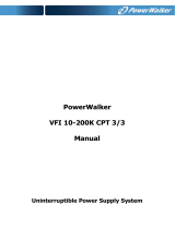
2.5.1 Internal Battery Connection
The models EVO DSP TM 10-30 KVA can be equipped with internal batteries. In such case
these devices may have very hazardous voltages on the Battery terminals.
When the UPS has battery inside, before doing any operation please do the following
points:
1 Remove the back UPS cover to access to the battery pack.
2 Connect the negative battery terminal A to the positive battery terminal B through
the included cable (see the following figure).
3 Connect the negative battery terminal C to the positive battery terminal D through
the included cable (see the following figure).
4 Replace the back UPS cover.
PAY ATTENTION: RISK OF ELECTRICAL SHOCK – HIGH BATTERY VOLTAGE
A-B and C-D battery terminals are disconnected in factory to reduce the risk of electrical
shock during shipment. After points 2 and 3 the NOMINAL TOTAL BATTERY VOLTAGE is
about 744 VDC (there are 62 batteries 12 VDC serial connected).
Figure - A-B and C-D Battery terminals connections

UPS EVO DSP TM 9 User’s manual
2.5.2 Power Connections
The power screw terminals are located on the lower front side of the UPS. Refer to the names of each
terminal to identify it during connection.
Connection terminals for all models with optional split Bypass
Battery terminals: use only to connect external battery.
Cables shall be passed through the hole under the connection terminals.
Make sure that all circuit breakers are “OFF”/“0” before starting with the installation.
Connections shall be done in the order below only.
2.5.2.1 Protective Earth (Ground) Connections
The device shall be earthed for a safe and reliable operation. Connect the PE ground
connectors before connecting any other cable
Input Protective Earth connection terminal (PE) of the UPS shall be connected to ground with a low
impedance connection.
PE terminals of the loads shall be connected to Output Protective Earth terminal of the UPS.
If there is an external battery cabinet present, it shall be grounded via Battery Protective Earth
terminal of the UPS. Battery case must be earthed only. Do not connect any DC/battery point to PE
earth.
2.5.2.2 Input Connection
Bring the circuit breaker on the distribution panel to “OFF”/“0” position before making
the connections.
Connect the phases to input (X2) L1, L2 and L3 terminals. Connect neutral to N terminal of X2
A definite phase sequence is needed for the UPS to operate. If you encounter “INP SEQ FAIL” alarm
message at start-up, stop and switch off the UPS, ensure the protection devices (breakers/isolators) on
the input distribution panels are “OFF”/“0”, then interchange any two phases on the UPS input only.

User’s manual 10 UPS EVO DSP TM
2.5.2.3 Separated Bypass Mains Input Connection (Optional)
Bring the circuit breaker on the distribution panel to “OFF” or “0” position before
making the connections
Connect the Phase of Bypass Input mains to Bypass (X3) L1 terminal.
Connect the Neutral to N terminal of X3.
2.5.2.4 External Battery Connection
Do not put the Battery fuses into the fuse holder (F5) before operating the equipment
and seeing the “NORMAL” message on the LCD.
Devices with internal batteries may have dangerous voltages on the Battery terminals
To connect external batteries, do the following:
Switch the circuit breaker of the external batteries to “OFF”/“0” position.
Connect the (-) pole of the external batteries to the Battery (-) terminal,
Connect the (+) pole of the external batteries to the Battery (+) terminal,
Connect the midpoint of the external batteries to the Battery (N) terminal.
Danger of explosion and fire if batteries of the wrong type are used.
2.5.2.5 Output Connection
To enable the short circuit protection feature of the UPS, each load shall be fed over a
separate circuit breaker chosen according to the load current. This may provide quick
disconnection of the short circuited load and operation continuity of the other loads. To
obtain maximum protection, the rating of each individual load circuit breaker shall have
the minimum value, which is enough to carry the full load current continuously.
Rated apparent and active power of the loads shall be less than the UPS power ratings.
Connect the loads to output (X4) L1 and N terminals. Do not use L2 and L3 terminals.
2.5.3 Communication Interfaces Connections
Related information is given in “Communication Interfaces” section.

UPS EVO DSP TM 11 User’s manual
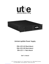
3 Operating Modes
There are three operating modes, which differ in the path of the energy flow.
UPS block diagrams and the energy flow path in each operating mode is shown below:
Figure – Block diagram and energy flow paths
(up: without Separate Bypass mains Input – down: with Separate Bypass mains Input)
Static Bypass
F3
F1
F6
F5
F2
Inverter
Rectifier
Inrush circuit
Battery
INPUT
3 Phases +
Neutral
OUTPUT
1 Phase +
Neutral
Static Bypass
F3
F1
F6
F5
F2
Inverter
Rectifier
Inrush circuit
Battery
INPUT
3 Phases +
Neutral
OUTPUT
1 Phase +
Neutral
F4
BYPASS
INPUT
1 Phase +
Neutral
Flow path:
Normal mode
Bypass mode
Battery mode

User’s manual 12 UPS EVO DSP TM
When UPS has no separate Bypass mains input, Bypass line is also fed from the mains input. Thus, if
such a device is in question, mains input shall be comprehended when the Bypass mains input is
referred in the following sections of the manual.
UPS behavior at the start-up is different from the usual operation. The UPS can only operate in Bypass
mode during start-up. So, in order for the UPS to start-up, frequency/waveform/RMS value of the
Bypass mains voltage shall be in acceptable limits and Bypass shall be enabled.
After start-up, the following applies:
Operating mode depends on the priority, Inverter, Rectifier and Bypass preferences made by the user
and mains, separate Bypass mains and battery voltages.
Priority and Inverter, Rectifier and Bypass preferences can be set by using the “COMMANDS” menu and
“EXTENDED CMNDS” submenu.
If operation in any of these modes is impossible, output voltage will not be present. In this case, loads
will not be fed, and “VSECFLR” alarm message is shown on the LCD instead of operating mode.
3.1 Bypass Mode
Devices without separate Bypass mains input, energy is drawn from the mains. In devices with separate
Bypass mains input, energy is drawn from the separate Bypass mains.
Loads are fed via static Bypass line.
Output voltage has the same amplitude, frequency and waveform as the input voltage.
Current drawn by the loads are only limited by the thermal/magnetic breakers over the energy flow
path.
Voltage, frequency and waveform of the Bypass supply shall be within their tolerance limits, and
Bypass shall be enabled for the UPS to operate in this mode.
When the upper provisions are met, the UPS works in Bypass mode in the following conditions:
During the start-up;
If the Bypass priority is selected;
If the Inverter is disabled or blocked;
In case of a prolonged Overload.
ECO Mode
You can save energy by selecting the Bypass priority. Efficiency in Bypass mode is higher than
the efficiency in Normal mode. If the Bypass priority is selected, the UPS will operate in Bypass
mode whenever the frequency/waveform/RMS value of Bypass mains voltage is within their
tolerance limits. If the Bypass voltage goes beyond these limits, the UPS switches into normal
operation.
Bypass mode does not provide perfect stability in frequency/waveform/RMS value of the
output voltage like in Normal mode. Thus, the use of this mode should be carefully
executed according to the level of protection required by the application.
Bypass mode does not provide electronic short circuit protection like in Normal mode. If
a short circuit occurs on the output during Bypass operation, the thermal/magnetic
protection will act and all loads will be de energized – load will be stopped.
Prolonged overloads may cause the thermal/magnetic protection to act. In this case, all
loads will be de energized – load output will be stopped.

UPS EVO DSP TM 13 User’s manual
3.2 Normal Mode
Energy is drawn from the mains input.
Loads are fed via the Rectifier and the Inverter. The AC voltage at the input is converted to a DC
voltage by the Rectifier. The Inverter converts this DC voltage to an AC voltage with a stable sinusoidal
waveform, amplitude and frequency.
Output voltage is sinusoidal and has a regulated amplitude and frequency. It is independent from the
input voltage.
The Inverter is synchronized in frequency with the Bypass mains input to enable load transfer to the
Bypass supply without any interruption, in case of an Overload or Inverter failure.
Voltage and frequency of the mains input shall be within their tolerance limits, and both the Rectifier
and the Inverter shall be enabled for the UPS to operate in this mode.
When the upper provisions are met, the UPS works in Normal mode in the following conditions:
If the Inverter priority is selected.
If the Bypass priority is selected but Bypass is disabled or frequency/waveform/RMS value of
Bypass mains voltage is not within acceptable limits.
3.3 Battery Mode
Energy is drawn from the batteries. Loads are fed via the Inverter.
Output voltage is sinusoidal and has a regulated amplitude and frequency. It is independent from the
battery voltage.
Battery voltage shall be within acceptable limits and the Inverter shall be enabled for the UPS to
operate in this mode.
When the upper provisions are met, the UPS works in Battery mode in the following conditions:
If Rectifier is disabled.
If the Rectifier is disabled or frequency/waveform/RMS value of mains voltage is not in
acceptable limits.

User’s manual 14 UPS EVO DSP TM
4 Control and Monitoring
4.1 Front Panel
The front panel located on the upper part of the UPS informs the user about operating status, alarm
conditions and measurements. It also provides access to controls and configuration parameters.
Front panel shown below consists of three parts:
1. Mimic panel provides basic information about the energy flow path and existing alarms;
2. LCD (liquid crystal display) offers detailed information and provides access to controls;
3. Keypad enables the user to move in the menu and to make selections.
4.1.1 Keypad
Functions of the buttons are given below:
BUTTON SYMBOL DEFINITION
MENU
To access to a menu or to exit from the current menu.
UP
Scrolls the available menus/values upwards. It increases the
value each time it is pushed when changing a parameter.
DOWN
Scrolls the available menus/values downwards. It decreases
the value each time it is pushed when changing a parameter.
ENTER
Enters the menu displayed on the screen. It makes selections
or confirms the choice/changes made.

UPS EVO DSP TM 15 User’s manual
4.1.2 Mimic Panel
Mimic panel is a diagram, which shows the path of energy flow in the UPS by means of several LED’s.
Definitions of LED status are shown below:
LED's
ID COLOR DEFINITION STATE
Input mains voltage is OK and Rectifier is active. Steady
Input mains voltage is OK and Rectifier is inactive.
Input mains voltage is very close to its upper/lower limit and Rectifier
is active.
Flashing
Line 1 Green
Input mains voltage is not OK. Off
Bypass voltage is OK. Steady
Bypass voltage is not OK and output voltage is synchronized to the
Bypass voltage.
Flashing
Line 2 Green
Bypass mains voltage is not OK and output voltage is not synchronized
to the Bypass voltage.
Off
Battery mode is active and battery voltage is OK.
UPS is performing Battery Test and battery voltage is OK.
Steady
Battery mode is active and battery voltage is close to its lower limit
(energy available in the battery is about to be depleted).
Battery Test is active and battery voltage is close to its lower limit
(energy available in the battery is about to be depleted).
Flashing
Battery Red
Rectifier is active and able to supply whole power required by the
Inverter.
Off
Load is fed via Inverter. Steady
Inverter Green
Inverter is not active. Off
Load is powered. Steady
Load is powered but UPS is overloaded. Flashing
Load Green
Output voltage is not OK. Off
Load is fed via static Bypass line. Steady
Bypass Yellow
Bypass is not active. Off
No alarms. Off
A minor priority alarm is present. Flashing
Fault Red
A major priority alarm is present. Steady

User’s manual 16 UPS EVO DSP TM
4.1.3 Liquid Crystal Display (LCD) and User Menu
LCD provides detailed information about device status, alarms and measurements. It also enables the
operator to manage the UPS. All information, commands and configuration parameters are given in a
menu, which has the following structure:
LCD consists of two rows and has the following structure:
Upper row: operating mode notification or “VSECFLR” alarm message
Lower row: menu, submenu, measurements
If there is no voltage on the output, “VSECFLR” alarm message is displayed on the upper row.
Operating mode is one of the notations below:
OPERATING MODE NOTATIONS
NORMAL Normal mode
BYPASS Bypass mode
BATT. Battery mode
Menu and submenu descriptions are given below.
“ALARMS” MENU
ALR = “XXXXXXXXXXXX”
ST = “XXXX-XXXXXXXX”
12 digit service codes.
Note these numbers before referring to Technical Service.
Alarm codes and names can be seen by entering into “ALR” submenu.
“ALARMS” table, with code, name and definition for each alarm, is given below.
All alarms except “VSEC NOT OK” are minor priority alarms.
MEASUREMENTS
COMMANDS
CO
NFI
GU
RATI
O
N
EVENTS
IDENTIFI
C
ATI
O
N
LAN
GU
A
G
E
ALARM
S
ALR
ST
DATE
TIME
EVENTS (xxx)
CLEAR EVENTS
PRIORITY
START B. TEST
BUZZER
COMM
EXTENDED CMNDS
RECTFR
INVRTR
BYPASS

UPS EVO DSP TM 17 User’s manual
“ALARMS” TABLE
CODE NAME DEFINITION
A01 BYP BADSHAPE
Bypass mains voltage is different than the Inverter reference signal (e.g. its
frequency is beyond synchronization limits or it has a Total Harmonic Distortion >
%10).
A02 BYP VOL HIGH
Bypass mains voltage is higher than its upper limit.
A03 BYP VOL LOW
Bypass mains voltage is lower higher than its lower limit.
A06 BYP SYN FAIL
Frequency of Bypass mains voltage is beyond the frequency range for Bypass
operation or Bypass mains voltage is very low.
A07 BYP SEQ FAIL
Phase sequence of Bypass mains voltages is not OK.
A08 MNBYP SW ON
Manual Bypass breaker is “ON”/“1”.
A09 INV TMP HIGH
Inverter block temperature is very high.
A10 OUT OVERLOAD
RMS current drawn from any of the output lines exceeds its nominal value.
A11 BYP ACT
Bypass mode is activated.
A12 INV NOT ACT
Inverter is not started due to a fault.
A13 INV BLCK
Inverter operation is automatically stopped due to a fault.
A14 VSEC NOT OK
Output voltage is beyond its limits.
A17 INP VOL HIGH
Input line/neutral voltage is higher than its upper limit.
A18 INP VOL LOW
Input line/neutral voltage is lower than its lower limit.
A21 INP SYN FAIL
Frequency of mains voltage is beyond the frequency range for Normal operation
or mains voltage is very low.
A22 INP SEQ FAIL
Phase sequence of input mains voltages is not OK.
A23 REC TMP HIGH
Rectifier block temperature is very high.
A24 REC OVERLOAD
RMS current drawn from any of the input lines exceeds its nominal value.
A25 VDC HIGH
DC bus voltages is higher than its upper limit
A26 VDC LOW
DC bus voltages is lower than its lower limit.
may mean that the battery is empty during Battery mode.
A27 REC NOT ACT
Rectifier is not started due to a fault.
A28 REC BLCK
Rectifier operation is automatically stopped due to a fault.
A30 TESTING BATT
The Battery Test is being performed.
A31 REDUND. LOST
Redundancy lost condition in Parallel System
A33 REC OFF
Rectifier is inactive.
A34 INV OFF
Inverter is inactive.
A35 BYP OFF
Bypass mode is inactive.
A36 BYP PRI HIGH
Priority is Bypass.
A37 BATT DISCHAR
Batteries are discharging after a mains failure.
A38 VDC NOT OK
DC bus voltage is out of its normal range.
A39 T-AMP HIGH
Ambient temperature exceeds its upper limit.
A40 GENSET ON
“Generator Friendly” operation is activated.
A41 EMG STOP ON
Emergency stop is activated.
A42 MINOR ALR
Minor priority alarm.
A43 MAJOR ALR
Major priority alarm.
A44 BATT TS FAIL
Batteries failed in the Battery Test.
A45 BATT CR OPEN
Battery circuit breaker is open.
A47 INV RX T-OUT
Communication between the Inverter and the front panel is lost.
A48 REC RX T-OUT
Communication between the Rectifier and the front panel is lost.

User’s manual 18 UPS EVO DSP TM
“MEASUREMENTS” MENU
MEASUREMENT DEFINITION
LD = XXX %
Ratio of the actual Inverter active power to its nominal value.
Vsc = XXX V
Output line/neutral voltage.
Isc = XXX A
Output line current.
Fo = XX.X Hz
Frequency of output Line/Neutral voltage.
Vby = XXX V
Bypass Line/Neutral voltage.
Vin = XXX,XXX,XXX V
Input Line/Neutral voltages.
Iin = XXX,XXX,XXX A
Input currents.
Fin = XX.X Hz
Frequency of input Line/Neutral voltages.
Vdc = XXX,XXX V
Positive and negative DC bus voltages.
Vbat = XXX,XXX V
Positive and negative battery branch voltages.
Ibat = ±XXX,±XXX A
Positive and negative battery branch currents.
Positive during charge, negative during discharge.
Tbat = XXX °C
Ambient temperature.
“COMMANDS” MENU
PRIORITY = INVRTR/BYPASS
Selects the priority for Normal mode or Bypass mode.
Push ENTER to switch between INVRTR and BYPASS.
START B. TEST
Push ENTER to start the Battery Test.
BUZZER = ENBLD/DSBLD
Enable or disable the buzzer.
Push ENTER to switch between ENBLD and DSBLD.
COMM = RS232/RS485
Push ENTER to switch between RS232/RS485 communication.
EXTENDED
CMNDS
Push ENTER to enter this submenu.
“EXTENDED CMNDS” SUBMENU
= ENBLD/DSBLD
Enable or disable operation of the Rectifier block.
Push ENTER to switch between ENBLD and DSBLD.
RECTFR
= BLCKD
Can be seen only when the Rectifier is blocked.
Push ENTER to remove the blockage and enable the Rectifier.
= ENBLD/DSBLD
Enable or disable the operation of the Inverter block.
Push ENTER to switch between ENBLD and DSBLD.
INVRTR
= BLCKD
Can be seen only when the Inverter is blocked.
Push ENTER to remove the blockage and enable the Inverter.
BYPASS = ENBLD/DSBLD
Enable or disable the operation of the Bypass thyristors.
Push ENTER to switch between ENBLD and DSBLD.
Page is loading ...
Page is loading ...
Page is loading ...
Page is loading ...
Page is loading ...
Page is loading ...
Page is loading ...
Page is loading ...
Page is loading ...
Page is loading ...
Page is loading ...
Page is loading ...
Page is loading ...
Page is loading ...
Page is loading ...
Page is loading ...
Page is loading ...
Page is loading ...
Page is loading ...
Page is loading ...
Page is loading ...
Page is loading ...
/