Kenmore 153.339572 User manual
- Category
- Water heaters & boilers
- Type
- User manual

Owner's Manual
POWER MISERTM 9
GAS WATER HEATER
FOR POTABLE WATER HEATING ONLY.
NOT SUITABLE FOR SPACE HEATING.
NOT FOR USE IN MOBILE HOMES.
MODEL NO.
153.339372 30 Gallon
153.339432 40 Gallon Short
153.339473 40 Gallon
153.339482 40 Gallon (LP)
153.339572 50 Gallon
• Safety Instructions
• Installation
• Operation
• Care and Maintenance
• Troubleshooting
• Parts List
For Your Safety
AN ODORANT ISADDED TO THE GAS USED BY THIS WATER HEATER.
This water heater complies with ANSI Z21.10.1-
current edition regarding the accidental or
unintended ignition of flammable vapors, such
as those emitted by gasoline.
Read and understand instruction
manual and safety messages
before installing, operating or
servicing this water heater.
Failure to follow instructions and
safety messages could result in
death or serious injury.
Instruction manual must remain
with water heater.
Si no puede leer o entender el ingles y necesita el manual de
instrucciones en espaSol, puede solicitarlo al 1-800-821-2017. NO
TRATE DE INSTALAR U OPERAR ESTE CALENTADOR DE AGUA
Sl NO ENTIENDE LAS INSTRUCCIONES. No hacer caso de esta
advertencia podria originar lesiones graves o mortales.
WARNING: If the information in these
instructions is not followed exactly, a fire
or explosion may result causing property
damage, personal injury or death.
m Do not store or use gasoline or other
flammable vapors and liquids in the
vicinity of this or any other appliance.
-- WHAT TO DO IF YOU SMELL GAS:
• Do not try to light any appliance.
• Do not touch any electrical switch; do
not use any phone in your building.
• Immediately call your gas supplier
from a neighbor's phone. Follow the
gas supplier's instructions.
• If you cannot reach your gas supplier,
call the fire department.
m lnstallation and service must be
performed by a qualified installer,
service agency or the gas supplier.
Sears, Roebuck and Co., Hoffman Estates, IL 60179 U.S.A
PRINTED IN THE U.S.A 0409 www.sears.com PART NO. 186497-001

Your safety and the safety of others is extremely important in the installation, use and servicing of this water heater.
Many safety-related messages and instructions have been provided in this manual and on your own water heater to warn you and others of
a potential injury hazard. Read and obey all safety messages and instructions throughout this manual. It is very important that the meaning
of each safety message is understood by you and others who install, use or service this water heater.
,_ I This is the safety alert symbol, it is used to alert you to potential personal injury hazards.
n
I
Obey all safety messages that follow this symbol to avoid possible injury or death.
DANGER indicates an imminently hazardous situation which, if not avoided, will
result in death or injury.
WARNING indicates a potentially hazardous situation which, if not avoided, could result
in death or injury.
CAUTION indicates a potentially hazardous situation which, if not avoided, could result
in minor or moderate injury.
CAUTION used without the safety alert symbol indicates a potentially hazardous
situation which, if not avoided, could result in property damage.
All safety messages will generally tell you about the type of hazard, what can happen if you do not follow the safety message and
how to avoid the risk of injury.
The California Safe Drinking Water and Toxic Enforcement Act requires the Governor of California to publish a list of substances known to
the State of California to cause cancer, birth defects, or other reproductive harm, and requires businesses to warn of potential exposure
to such substances. WARNING: This product contains a chemical known to the State of California to cause cancer, birth defects, or other
reproductive harm. This appliance can cause low-level exposure to some of the substances included in the act.
IMPORTANT DEFINITIONS
• Qualified Technician: A qualified technician must have ability equivalent to a licensed tradesman in the fields of plumbing, air supply,
venting, and gas supply, including a thorough understanding of the requirements of the National Fuel Gas Code as it relates to the
installation of gas fired water heaters The qualified technician must also be familiar with the design features and use of flammable vapor
ignition resistant water heaters, and have a thorough understanding of this instruction manual
• Service Agency: A service agency also must have ability equivalent to a licensed tradesman in the fields of plumbing, air supply, venting
and gas supply, including a thorough understanding of the requirements of the National Fuel Gas Code as it relates to the installation of
gas fired water heaters The service agency must also have a thorough understanding of this instruction manual, and be able to perform
repairs strictly in accordance with the service guidelines provided by the manufacturer
• Gas Supplier: The natural gas or propane utility or service who supplies gas for utilization by the gas burning appliances within this
application The gas supplier typically has responsibility for the inspection and code approval of gas piping up to and including the natural
gas meter or propane storage tank of a building Many gas suppliers also offer service and inspection of appliances within the building
FIRE AND EXPLOSION HAZARD
Can result in serious injury or death
Do not store or use gasoline or other
flammable vapors and liquids in the vicinity of this
or any other appliance. Storage of or use of
gasoline or other flammable vapors or liquids in the
vicinity of this or any other appliance can result in
serious injury or death.
Read and follow water heater warnings and instructions.
© Sears, Roebuck and Co.

Read and understand instruction
manual and safety messages
before installing, operating or
servicing this water heater.
Failure to follow instructions and
safety messages could result in
death or serious injury.
Instruction manual must remain
with water heater.
Fire Hazard
For continued protection against
riskof fire:
• Do not install water heater on
carpeted floor.
• Do not operate water heater if
flood damaged.
Water temperature over 125°F
(52°C) can cause severe burns
instantly resulting in severe injury
or death.
Children, the elderly, and the
physically or mentally disabled
are at highest riskforscald injury.
Feel water before bathing or
showering.
Temperature limiting valves are
available.
Read instruction manual for safe
temperature setting
Fire or Explosion Harzard
• Do not store or use gasoline or other flammable vapors and
liquids in the vicinity of this or any other appliance.
• Avoid all ignition sources if you smell Natural or LP gas.
• Do not expose water heater control to excessive gas
pressure.
• Use only gas shown on rating plate.
• Maintain required clearances to combustibles.
• Keep ignition sources away from faucets after extended
period of non-use.
Read instruction manual before
installing, using or servicing
water heater.
Explosion Hazard
• Overheated water can cause
water tank explosion.
• Properly sized temperature
and pressure relief valve must
be installed in opening
provided.
Breathing Hazard - Carbon Monoxide Gas
• Install vent system in accordance with
codes.
• Do not operate water heater if flood
damaged
• High altitude orifice must be installed for
operation above 7,700 feet (2,347m).
• Do not operate if soot is present.
• Do not obstruct water heater air intake
with insulating jacket.
• Do not place chemical vapor emitting
products near water heater.
• Gas and carbon monoxide detectors
are available.
Breathing carbon monoxide can cause brain damage or
death. Always read and understand instruction manual.
Improper installation and use may result
in property damage.
• Do not operate water heater if flood damaged.
• Inspect and replace anode.
• Install in location with drainage.
• Fill tank with water before operation.
• Be alert for thermal expansion.
Refer to instruction manual for installation and service.

SAFE INSTALLATION, USE AND SERVICE ................................................................................................. 2
SAFETY PRECAUTIONS ........................................................................................................................... 2-3
PRODUCT WARRANTY ................................................................................................................................ 6
CUSTOMER RESPONSIBILITIES ................................................................................................................. 7
PRODUCT SPECIFICATIONS ...................................................................................................................... 8
MATERIALS AND BASIC TOOLS NEEDED .................................................................................................. 9
TYPICAL INSTALLATION ............................................................................................................................ 10
IMPORTANT INFORMATION ABOUT THIS WATER HEATER .................................................................... 11
Installation Checklist ................................................................................................................................................ 11
INSTALLATION INSTRUCTIONS ........................................................................................................... 12-15
Removing the Old Water Heater ............................................................................................................................. 12
Location Requirements ........................................................................................................................................... 13
Site Location ........................................................................................................................................................... 13
Insulation Blankets .................................................................................................................................................. 14
Clearances and Accessibility ............................................................................................................................. 14-15
Filling the Water Heater .......................................................................................................................................... 15
GAS SUPPLY .......................................................................................................................................... 15-16
Gas Requirements .................................................................................................................................................. 15
Gas Piping .............................................................................................................................................................. 15
Gas Pressure .......................................................................................................................................................... 16
Gas Pressure Testing .............................................................................................................................................. 16
LP Gas Only ............................................................................................................................................................ 16
COMBUSTION AIR SUPPLY & VENTILATION ...................................................................................... 17-20
Unconfined Space ................................................................................................................................................... 17
Confined Space ...................................................................................................................................................... 17
All Air from Inside the Building ........................................................................................................................... 17-18
All Air from Outdoors ............................................................................................................................................... 18
Louvers and Grilles ............................................................................................................................................ 18-19
Vent Pipe System ................................................................................................................................................... 19
Draft Hood Installation ............................................................................................................................................ 19
Vent Pipe Size ........................................................................................................................................................ 19
Vent Connectors ................................................................................................................................................ 19-20
Chimney Connection ............................................................................................................................................... 20
Vertical Exhaust Gas Vent ...................................................................................................................................... 20
WATER SYSTEM PIPING ....................................................................................................................... 21-22
Piping Installation .................................................................................................................................................... 21
Closed System/Thermal Expansion ........................................................................................................................ 22
Temperature and Pressure Relief Valve ................................................................................................................. 22
T&P Relief Valve and Pipe Insulation ........................................................................................................................ 22

OPERATINGYOURWATERHEATER...................................................................................................23-25
LightingInstructions................................................................................................................................................23
CheckingtheDraft..................................................................................................................................................24
BurnerFlames........................................................................................................................................................24
EmergencyShutDown...........................................................................................................................................24
WaterTemperatureRegulation..........................................................................................................................24-25
SERVICEANDADJUSTMENT...............................................................................................................26-28
Tank(Sediment)Cleaning......................................................................................................................................26
VentSystemInspection..........................................................................................................................................26
BurnerInspection....................................................................................................................................................26
BurnerCleaning......................................................................................................................................................26
Housekeeping.........................................................................................................................................................27
AnodeRodInspection............................................................................................................................................27
Temperature-PressureReliefValveOperation.......................................................................................................27
DrainingandFlushing........................................................................................................................................27-28
Service....................................................................................................................................................................28
MAINTENANCEOFYOURWATERHEATER........................................................................................29-32
ReplacementParts.................................................................................................................................................29
ExternalInspection&CleaningoftheBase-RingFilter.........................................................................................29
RemovingtheManifold/BurnerAssembly...............................................................................................................29
RemovingtheBurnerfromtheManifold/BurnerAssembly....................................................................................29
ReplacingtheThermocouple.............................................................................................................................29-30
ReplacingthePilot/PilotTubeAssembly...............................................................................................................30
CleaningtheCombustionChamberandFlame-arrestor........................................................................................30
ReplacingtheManifold/BurnerAssembly...............................................................................................................31
PiezoelectricIgniterSystem...................................................................................................................................31
TestingtheIgniterSystem......................................................................................................................................32
RemovingandReplacingtheGasControlValve/Thermostat................................................................................32
FVlRSystemOperationalChecklist.......................................................................................................................32
TROUBLESHOOTINGGUIDE................................................................................................................33-35
StartUpConditions............................................................................................................................................33-34
OperationalConditions......................................................................................................................................34-35
TROUBLESHOOTINGCHART...............................................................................................................36-37
PILOTLIGHTTROUBLESHOOTINGFLOWCHART...................................................................................38
PARTSORDERLIST...................................................................................................................................39

9 - YEAR LIMITED WARRANTY ON WATER HEATER
For nine years from the date of purchase, if this water heater is installed and operated in a single-family home in accordance
with the owner's manual instructions and all local applicable plumbing codes, Sears will:
1. Supply free water heater parts for those that are defective in material or workmanship.
2. Supply a free water heater for one that develops a leak.
For the second through the ninth year from the purchase date, you must pay the labor cost for installation of parts or water heater.
For commercial, institutional, industrial or residential use by two or more families, the above limited warranty is only for two
years. During the second year you must pay the labor cost for parts or water heater installation.
1 - YEAR EXCLUSIVE KENMORE LABOR WARRANTY
For the first year from the date of purchase, Sears will, free of charge, supply and install new water heater parts for defective
ones or a new water heater for one that develops a leak.
WARRANTY SERVICE
To obtain warranty service, call 1-800-4-MY-HOME ® (1-800-469-4663).
This warranty applies only while this product is in use in the United States.
This warranty gives you specific legal rights, and you may also have other rights which vary from state to state.
SEARS, ROEBUCK AND CO., Dept.817WA, Hoffman Estates, IL 60179
The price of your water heater does not include a free checkup service call. On water heater installations arranged by Sears, Sears
warrants the installation.
A charge will be made on service calls due to poor or incomplete installation. These include:
a. Adjusting thermostat b. Condensation c. Leaks in pipes or fittings
Master Protection Agreements
Congratulations on making a smart purchase. Your new
Kenmore ® product is designed and manufactured for years
of dependable operation. But like all products, it may require
preventive maintenance or repair from time to time. That's when
having a Master Protection Agreement can save you money and
aggravation.
The Master Protection Agreement also helps extend the life of your
new product. Here's what the Agreement* includes:
• Parts and labor needed to help keep products operating
properly under normal use, not just defects. Our coverage
goes well beyond the product warranty. No deductibles, no
functional failure excluded from coverage-- real protection.
• Expert service by a force of more than 10,000 authorized
Sears service technicians, which means someone you can
trust will be working on your product.
• Unlimited service calls and nationwide service, as often as
you want us, whenever you want us.
• "No-lemon" guarantee - replacement of your covered product
if four or more product failures occur within twelve months.
• Product replacement if your covered product can't be fixed.
• Annual Preventive Maintenance Check at your request - no
extra charge.
• Fast help by phone - we call it Rapid Resolution - phone
support from a Sears representative on all products. Think of
us as a "talking owner's manual."
• Power surge protection against electrical damage due to
power fluctuations.
• $250 Food Loss Protection annually for any food spoilage
that is the result of mechanical failure of any covered
refrigerator or freezer.
• Rental reimbursement if repair of your covered product takes
longer than promised.
• 10% discount off the regular price of any non-covered repair
service and related installed parts.
Once you purchase the Agreement, a simple phone call is all that it
takes for you to schedule service. You can call anytime day or night,
or schedule a service appointment online.
The Master Protection Agreement is a risk free purchase. If you
cancel for any reason during the product warranty period, we
will provide a full refund. Or, a prorated refund anytime after the
product warranty period expires. Purchase your Master Protection
Agreement today!
Some limitations and exclusions apply. For prices and additional
information in the U.S.A. call 1-800-827-6655.
* Coverage in Canada varies on some items. For full details,
call Sears Canada at 1-800-361-6665.
Sears Installation Service
For Sears professional installation of home appliances, garage door
openers, water heaters, and other major home items, in the U.S.A.
or Canada call 1-800-4-MY-HOME ®.

ThankYouforpurchasingaKenmorewaterheater.Properlyinstalled
andmaintained,itshouldgiveyouyearsoftroublefreeservice.If
youshoulddecidethatyouwantthenewwaterheaterprofessionally
installedbySearscall1-800-4-MY-HOME®.Theywillarrangefor
prompt,qualityinstallationbySearsauthorizedcontractors.
Abbreviations Found In This Instruction Manual:
• CSA- Canadian Standards Association
• ANSI- American National Standards Institute
• N FPA- National Fire Protection Association
• ASME - American Society of Mechanical Engineers
• GAMA- Gas Appliance Manufacturers Association
Important Information About This Water Heater:
This gas water heater was manufactured to voluntary safety
standards to reduce the likelihood of a flammable vapor ignition
incident. New technology used in meeting these standards makes this
product more sensitive to installation errors or improper installation
environments. Please review the Installation Checklist found at the
end of the installation instructions section and make any required
installation upgrades or changes.
This manual contains instructions for the installation, operation,
and maintenance of the gas-fired water heater, tt also contains
warnings through out the manual that you must read and be aware
of. All warnings and all instructions are essential to the proper
operation of the water heater and your safety. Since we cannot put
everything on the first few pages, READ THE ENTIRE MANUAL
BEFORE ATTEMPTING TO INSTALL OR OPERATE THE WATER
HEATER.
The installation must conform with these instructions and the
local code authority having jurisdiction. In the absence of local
codes, installations shall comply with the following:
In the United States: The National Fuel Gas CodeANSI Z223.1/
NFPA 54. This publication is available from the Canadian
StandardsAssociation, 8501 East Pleasant Valley Rd, Cleveland
Ohio 44131, or The National Fire Protection Association, 1
Batterymarch Park, Quincy, MA 02269.
• If after reading this manual you have any questions or do not
understand any portion of the instructions, call the Sears Service
Center.
Carefully plan the place where you are going to put the water heater.
Correct combustion, vent action, and vent pipe installation are
very important in preventing death from possible carbon monoxide
poisoning and fires. See Figure 1.
• Examine the location to ensure the water heater complies with
the Installation Instructions section in this manual.
For California installation, this water heater must be braced,
anchored, or strapped to avoid falling or moving during an
earthquake. See instructions for correct installation procedures.
Instructions may be obtained from California's Office of the
State Architect, 1102 Q Street, Suite 5100, Sacramento, CA
95811. Instructions can also be downloaded to your computer
at www.dsa.dgs.ca.gov/Pubs.
Massachusetts Code requires this water heater to be installed in
accordance with Massachusetts 248-CMR 2.00: State Plumbing
Code and 248-CMR 5.00.
Complies with 40 Ng/J NOx requirements of Texas and most
California AQM Districts.
Excessive Weight Hazard
Use two or more people to move and install the water heater.
Failure to do so can result in injury (including back injury).
IMPORTANT: Do not remove any permanent instructions, labels, or
the data label from either the outside of the water heater or on the
inside of water heater panels.
• Remove exterior packaging and place installation components
aside.
• Inspect all parts for damage prior to installation and
start-up.
• Completely read all instructions before attempting to assemble
and install this product.
• After installation, dispose of/recycle all packaging materials.

MODEL TANK CAPACITY TYPE INPUT RECOVERY MINIMUM DIAMETER DIMENSIONS
NUMBER IN GALS (LTRS) OF RATE
RATE GALS. VENT PIPE INCHES INCHES (mm)
GAS (Btu/hr) PER HOUR DIA. INCHES (mm) HEIGHT TO
@ 90°F RISE (mm) JACKET TOP
153.339372 30 (114) Natural 35,500 36.34 3 (76) OR 4 (102) 16 (406) 57.00 (1448)
153.339432 40 (151) Natural 40,000 40.94 3 (76) OR 4 (102) 20 (508) 47.75 (1213)
153.339473 40 (151) Natural 40,000 40.94 3 (76) OR 4 (102) 18 (457) 58.14 (1477)
153.339482 40 (151) Propane 36,000 36.85 3 (76) OR 4 (102) 18 (457) 58.14 (1477)
(L.P.)
153.339572 50 (189) Natural 40,000 40.94 3 (76) OR 4 (102) 20 (508) 57.28 (1455)

MATERIALS NEEDED
To simplify the installation Sears has available the installation parts shown below. You may or may not need all of these materials,
depending on your type of installation.
EXPANSION TANKS FOR
THERMAL EXPANSION
CONDITIONS AVAILABLE
IN 2 GALLONS
(7.6 LITERS) AND
5 GALLONS (18.9 LITERS)
CAPACITY THROUGH
LOCAL SEARS STORE
OR SERVICE CENTER.
I
WATER HEATER INSTALLATION KIT WITH
FLEXIBLE CONNECTORS FOR 3/4"
(19.05 ram) OR 1/2" (12.7 mm) THREADED OR
COPPER PLUMBING AND FLEXIBLE WATER
HEATER GAS CONNECTOR WITH FITTINGS.
METAL DRAIN PANS
AVAILABLE IN 20" (508
mm) DIAMETER FOR
WATER HEATERS HAVING A
DIAMETER 18" (457 mm) OR
LESS, 24" (610mm) DIAMETER
FOR WATER HEATERS HAVING
A DIAMETER 22" (559 mm)
OR LESS AND AVAILABLE IN
28" (711 mm) DIAMETER FOR
WATER HEATERS HAVING A
DIAMETER 26" (660 mm) OR
LESS.
BASIC TOOLS
You may or may not need all these tools, depending on your
type of installation. These tools can be purchased at your local
Sears Store.
• Pipe Wrenches (2) 14" (356 mm)
• Screwdriver
• Tin Snips
• 6' (1.82 m) Tape or Folding Ruler
• Garden Hose
• Drill
• Pipe Dope or Teflon Tape
DRILL
SLOT-HEAD SCREWDRIVER
PHILLIPS SCREWDRIVER
TIN SNIPS
ROLL OF TEFLON
TAPE (USE ONLY ON
WATER CONNECTIONS)
PIPE DOPE
(SQUEEZE TUBE)
USE FOR WATER AND GAS
CONNECTIONS
GARDEN HOSE
6 FOOT TAPE
PIPE WRENCH
ADDITIONAL TOOLS NEEDED
WHEN SWEAT SOLDERING
• Tubing Cutters or Hacksaw
• Propane Tank
• Soft Solder
• Solder Flux
• Emery Cloth
• Wire Brushes
TUBING CUTTER
HACKSAW
3/4" (19 mm) WIRE BRUSH
1/2" (13 mm)WIRE BRUSH
\
1
PROPANE
TORCH
ROLL OF
EMERY CLOTH
ROLL OF LEAD-FREE
SOFT SOLDER
SOLDER
FLUX

GET TO KNOW YOUR WATER HEATER - GAS MODELS
A Vent Pipe
B Draft Hood
C Anode (Not Shown)
D Hot Water Outlet
E Insulation
F Gas Supply Piping
G Manual Gas Shut-off Valve
H Ground Joint Union
I Drip Leg (Sediment Trap)
J Inner Door
K Outer Door
L Union
M Inlet Water Shut-off Valve
N Cold Water Inlet
O Inlet Dip Tube
P Temperature-Pressure Relief Valve
Q Rating Plate
R Flue Baffle
S Gas Control Valve/Thermostat
T Drain Valve
U Pilot and Main Burner
V Flue
W Metal Drain Pan
X Piezo Igniter
Y Base-Ring Filter
* INSTALL INACCORDANCE
WITH LOCAL CODES.
* DRIP LEG AS REQUIRED
BY LOCAL CODES.
TO VENT
TERMINATION ON
ROOF
_ A
B
D
E
F
G
H_
V
INSTALL THERMAL EXPANSION
TANK OR DEVICE IF WATER
HEATER IS INSTALLED IN A
CLOSED WATER SYSTEM
M
VACUUM RELIEF
VALVE
*INSTALL PER
LOCAL CODES
_\ p
(S) GAS CONTROL VALVE/
THERMOSTAT: WHITE-RODGERS
GAS CONTROL KNOB
WATER TEMPERATURE DIAL
(ADJUSTING DIAL)
"OFF .... PILOT ON"
POSITION POSITION POSITION
TOP VIEW
(U) MANIFOLD/BURNER ASSEMBLY
MAIN BURNER
'_ THERMOCOUPLE
,, P,LOTTUBE
CC_-'_ J_ "IGNITER WIRE
IGNITER RO
,f- MANIFOLD TUBE
MANIFOLD DOOR _
PIPE
NOT CAP OR PLUG.)
" 6" MAXIMUM
AIR GAP
/
w
* ALL PIPING MATERIALS TO BE
SUPPLIED BY CUSTOMERS.
FIGURE 1.
10

This gas water heater was manufactured to voluntary safety standards to reduce the likelihood of a flammable vapor ignition incident.
The new technology used in meeting these standards makes this product more sensitive to installation errors. Please review the
following checklist and make any required installation upgrades or changes.
Questions? Contact Sears at 1-800-4-MY-HOME (1-800-469-4663).
Installation Checklist
Water Heater Location
Water heater location is important and
performance. Please check the following:
[]
can affect system
Installation area free of corrosive elements and flammable
materials.
[] Centrally located with the water piping system (For new
installations). Located as close to the gas piping and vent
pipe system as possible.
[] Located indoors and in a vertical position. Protected from
freezing temperatures.
[] Proper clearances from combustible surfaces
maintained and not installed directly on a carpeted floor.
[] Provisions made to protect the area from water damage.
Metal drain pan installed and piped to an adequate drain.
[] Sufficient room to service the water heater. See Clearances
and Accessibility section of this manual.
[] Water heater not located near an air moving device.
[] Is the installed environment dirty (excessive amounts of
lint, dirt, dust, etc.)? If so, the base-ring filter located on
the bottom of the water heater will need to be cleaned
periodically. Refer to the "Maintenance of your Water
Heater" section of this manual for information on cleaning
the base-ring filter.
Combustion Air Supply and Ventilation
[]
[]
Check for sufficient combustion air supply. Insufficient air for
the combustion of gas wilt result in the flame becoming "lazy",
thereby allowing heat to build up in the combustion chamber.
This excessive heat wilt cause a thermal switch on the door
assembly to trip. Is the water heater installed in a closet or other
small, enclosed space? If so:
Are there openings for make-up air to enter and exit the
room/area?
[]
[]
[]
Are the openings of sufficient size? Remember, if there
are other gas-fired or air-consuming appliances in the
same room, you need more make-up air. Refer to the
"Installation Instructions" and "Combustion Air Supply and
Ventilation" sections for specific requirements.
Make sure that fresh air is not taken from areas that contain
negative pressure producing devices such as exhaust fans,
dryers, fireplaces, etc.
Is there a furnace/air handler in the same room space as
the water heater? If so, has a return air duct system been
attached that exits the room? If so, check for leaks on the
air duct system. If no air duct system is present, correct
immediately by contacting a local Heating, Ventilation, Air-
Conditioning & Refrigeration (HVAC-R) authorized service
provider.
Use a fresh air supply that is free of corrosive elements and
flammable vapors.
[]
[]
Fresh air openings must be sized correctly with consideration
given to the blocking effect of louvers and grilles.
Ductwork must be the same cross-sectional area as the
openings.
Vent Pipe System
Check for proper drafting at the water heater draft hood. Refer
to the "Checking the Draft" section of this manual for the test
procedure. If the procedure shows insufficient draft is present,
please check the following:
Draft hood properly installed.
[]
[]
[]
[]
Vent connectors securely fastened with screws and
supported properly to maintain six inch clearance.
Vent connector made of approved material and sized
correctly.
Vent pipe system installed according to all local and state
codes or, in the absence of local and state codes, the
"National Fuel Gas Code", ANSI Z223.1(NFPA 54)-current
edition.
[] Flue baffle properly positioned in the flue tube.
[] Check the vent system for restrictions/obstructions and
check the vent termination height. Refer to the "Combustion
Air Supply and Ventilation" section of this water heater
manual for specific requirements.
[] Recheck for sufficient combustion air supply.
Water System Piping
[] Temperature and pressure relief valve properly installed with
a discharge line run to an open drain and protected from
freezing.
[] All piping properly installed and free of leaks.
[] Heater completely filled with water.
[] Closed system pressure build-up devices installed.
[] Mixing valve (when applicable) installed per manufacturer's
instructions (See "Water Temperature Regulation" section).
Gas Supply and Piping
[] Gas type is the same as that listed on the water heater rating
plate.
[] Gas line equipped with shut-off valve, union, and drip leg.
[] Use pipe joint compound or teflon tape marked as being
resistant to the action of petroleum [Propane (L.R)] gases.
[]
[]
Adequate pipe size and approved pipe material.
An approved noncorrosive leak detection solution used
to check all connections and fittings for possible gas leaks.
Correct any leak found.
11

Removing the Old Water Heater Q
Q
MANUAL GAS
SHUT-OFFVALVE_.._._
GROUND_
JOINT
UNION
CHECK WITH
LOCAL UTILITY
FOR MINIMUM HEIGHT
DRIP
@
DISCHARGE PIPE
(DO NOT CAP
OR PLUG)
6" MAXIMUM
AIR GAP
SUITABLE _f
DRAIN
FIGURE 2.
©
©
Turn "OFF" the gas supply to
the water heater.
If the main gas line shutoff valve
serving all gas appliances is used,
also shut "OFF" the gas at each
appliance. Leave allgas appliances
shut "OFF" until the water heater
installation is completed. See
Figures 2 and 3.
FIGURE 3.
Open a nearby hot water faucet
until the water is no longer hot.
When the water has cooled, turn
"OFF" the water supply to the water
heater at the water shut off valve
orwater meter. Some installations
require that the water be turned off
to the entire house. See Figures 2
and 4.
FIGURE 4.
Q Check to make the is "OFF" to the water
again
sure
gas
supply
heater. Then disconnect the gas supply connection from the
gas control valve.
• Burn hazard
• Hotwater discharge.
• Keep hands clear of drain
valve discharge.
®
®
Attach a hose to the water heater
drain valve and put the other end
in a floor drain or outdoors. (See
Figures 2 and 5.) Open the water
heater drain valve. The water
passing out of the drain valve
may be extremely hot. To avoid
being scalded, make sure all
connections are tight and that the
water flow is directed away from
any person.
FIGURE 5.
Disconnect the vent pipe from the draft hood where it connects
to the water heater. In most installations the vent pipe can
be lifted off after any screw or other attached devices are
removed. Dispose of the draft hood. The new water heater
has a draft hood which must be used for proper operation.
If you have copper piping to the water heater, the two copper
water pipes can be cut with a hacksaw approximately four
inches away from where they connect to the water heater.
See Figure 6. This will avoid cutting off pipes too short.
Additional cuts can be made later if necessary. Disconnect the
temperature-pressure relief valve drain line. When the water
heater is drained, disconnect the hose from the drain valve.
Close the drain valve. The water heater is now completely
disconnected and ready to be removed.
FIGURE 6.
If you have galvanized pipes to the water heater, loosen
the two galvanized pipes with a pipe wrench at the union in
each line. Also disconnect the piping remaining to the water
heater. See Figure 7. These pieces should be saved since
they may be needed when reconnecting the new water heater.
Disconnect the temperature-pressure relief valve drain line.
When the water heater is drained, disconnect the hose from
the drain valve. Close the drain valve. The water heater
is now completely disconnected and ready to be removed.
Mineral buildup or sediment may have accumulated in the
old water heater. This causes the water heater to be much
heavier than normal and this residue, if spilled out, could
cause staining.
FIGURE 7.
12

Location Requirements
I Carbon Monoxide Poisoning Hazard
Do not install in a mobile home.
Doing so can result in carbon monoxide poisoning and death.
area of the water heater, leave the area immediately and call
the fire department from a neighbor's home. Do not attempt to
clean the spill until all ignition sources have been extinguished.
The FVIR System is designed to reduce the risk of flammable
vapor-related fires. The patented system protects your family by
trapping the burning vapors within the water heater combustion
chamber through the special flame-arrestor. The burning vapors
literally "burn themselves out" without escaping back into the
room. In the event of a flammable vapor incident, the FVIR
System disables the water heater by shutting off the gas supply
to the water heater's burner and pilot, preventing re-ignition
of any remaining flammable vapors in the area. This will not
prevent a possible fire/explosion if the igniter is depressed
and flammable vapors have accumulated in the combustion
chamber with the pilot light off. If you suspect a flammable
vapor incident has occurred, do not use this appliance. Do not
attempt to light this appliance, or depress the igniter button
if you suspect flammable vapors have accumulated inside or
outside the appliance. Immediately call a qualified technician to
inspect the appliance. Water heaters subjected to a flammable
vapors incident will show a discoloration on the flame-arrestor
and require replacement of the entire water heater.
Rarnrnable Vapors
FIRE AND EXPLOSION HAZARD
Can result in serious injury or death
_Do not store or use gasoline or other flammable
vapors and liquids in the vicinity of this or any other
appliance. Storage of or use of gasoline or other
flammable vapors or liquids in the vicinity of this or any
other appliance can result in serious injury or death.
Read and follow water heater warnings and instructions.
Fire or Explosion Hazard
• Read instruction manual before installing, using or
servicing water heater.
• Improper use may result in fire or explosion.
• Maintain required clearances to combustibles.
Keep combustibles such as boxes, magazines, clothes, etc.
away from the water heater area.
Site Location
• Select a location near the center of the water piping system.
The water heater must be installed indoors and in a vertical
position on a level surface. DO NOT install in bathrooms,
bedrooms, or any occupied room normally kept closed.
• Locate the water heater as close to the chimney or gas
vent as practical. Consider the vent system piping and
combustion air supply requirements when selecting the
water heater location. The venting system must be able
to run from the water heater to termination with minimal
length and elbows.
• Locate the water heater near the existing gas piping. If
installing a new gas line, locate the water heater to minimize
the pipe length and elbows.
• The water heater should be located in an area not subject
to freezing temperatures. Water heaters located in
unconditioned spaces (i.e., attics, basements, etc.) may
require insulation of the water piping and drain piping
to protect against freezing. The drain and controls must
be easily accessible for operation and service. Maintain
proper clearances as specified on the rating plate.
• Do not locate the water heater near an air-moving device.
The operation of air-moving devices such as exhaust fans,
ventilation systems, clothes dryers, fireplaces, etc., can
affect the proper operation of the water heater. Special
attention must be given to conditions these devices may
create. Flow reversal of flue gases may cause an increase
of carbon monoxide inside of the dwelling (Figure 8).
• If the water heater is located in an area that is subjected to
lint and dirt, it may be necessary to periodically clean the
base-ring filter and flame-arrestor (see External Inspection
& Cleaning of the Flame-arrestor).
• This water heater is not for use in manufactured (mobile)
homes or outdoor installation.
NOTE: This water heater must be installed according to all local
and state codes or, in the absence of local and state codes, the
"National Fuel Gas Code", ANSI Z223.1(NFPA 54)-current edition.
Do not use or store flammable products such as gasoline,
solvents, or adhesives in the same room or area near the
water heater. If such flammables must be used, all gas burning
appliances in the vicinity must be shut off and their pilot lights
extinguished. Open the doors and windows for ventilation while
flammable substances are in use.
If flammable liquids or vapors have spilled or leaked in the
13
REVERSE FLOW
L OF GASES
FIGURE 8

Property Damage Hazard
• AJlwater heaters eventuafly leak
• Do not install without adequate drainage.
IMPORTANT: The water heater should be located in an area
where leakage of the tank or connections will not result in damage
to the area adjacent to the water heater or to lower floors of the
structure. Due to the normal corrosive action of water, the tank wilt
eventually leak after an extended period of time. Also any external
plumbing leak, including those from improper installation, may
cause early failure of the tank due to corrosion if not repaired. If
the homeowner is uncomfortable with making the repair a qualified
technician should be contacted. A suitable metal drain pan should
be installed under the water heater as shown below, to help protect
the property from damage which may occur from condensate
formation or leaks in the piping connections or tank. The pan must
limit the water level to amaximum depth of 1-3/4" and be two inches
wider than the heater and piped to an adequate drain. NOTE: The
pan must not restrict combustion air flow. Locate the water heater
near a suitable indoor drain. Outside drains are subject to freezing
temperatures which can obstruct the drain line. The piping should
be at least 3/4" ID and pitched for proper drainage.
METAL
DRAIN
PAN
/
PIPED TO AN
ADEQUATE DRAIN
AT LEAST 2" GREATER THAN THE =u_'7 _
/
DIAMETER OF THE WATER HEATER,
FIGURE 9.
Water heater life depends upon water quality, water usage,
water temperature and the environment in which the water
heater is installed. Water heaters are sometimes installed in
locations where leakage may result in property damage, even
with the use of a metal drain pan piped to a drain. However,
unanticipated damage can be reduced or prevented by a leak
detector or water shut-off device used in conjunction with a
piped metal drain pan. These devices are available from some
plumbing supply wholesalers and retailers, and detect and react
to leakage in various ways:
• Sensors mounted in the metal drain pan that trigger an
alarm or turn off the incoming water to the water heater
when water is detected.
• Sensors mounted in the metal drain pan that turn off the
water supply to the entire home when water is detected in
the drain pan.
• Water supply shut-off devices that activate based on the
water pressure differential between the cold water and hot
water pipes connected to the water heater.
• Devices that wilt turn off the gas supply to a gas water
heater while at the same time shutting off its water supply.
Insulation Blankets
Insulation blankets available to the general public for external
use on gas water heaters are not necessary with Kenmore
products. The purpose of an insulation blanket is to reduce the
standby heat toss encountered with storage tank heaters. Your
Kenmore water heater meets or exceeds the National Appliance
Energy Conservation Act standards with respect to insulation
and standby loss requirements, making an insulation blanket
unnecessary.
14
Breathing Hazard - Carbon Monoxide Gas
• Do not obstruct water heater air
intakewith insulating blanket.
• Gas and carbon monoxide detectors
_i_:"_" _° ,:_ are available.• Install water heater in accordance
_'o'.:_ with the instruction manual.
I
Breathing carbon monoxide can cause brain damage or
death. Always read and understand instruction manual.
_1_ WARNING
Should you choose to apply an insulation blanket to this
heater, you should follow these instructions (See Figure 1
for identification of components mentioned below). Failure to
follow these instructions can restrict the air flow required for
proper combustion, potentially resulting in fire, asphyxiation,
serious personal injury or death.
• Do not apply insulation to the top of the water heater, as
this wilt interfere with safe operation of the draft hood.
Do not cover the outer door, thermostat or temperature &
pressure relief valve.
• Do not allow insulation to come within 2" (50.8 mm) of
the floor to prevent blockage of combustion air flow to the
burner.
Do not cover the instruction manual. Keep it on the side of
the water heater or nearby for future reference.
Do obtain new warning and instruction labels from Sears
for placement on the blanket directly over the existing
labels.
Do inspect the insulation blanket frequently to make certain
it does not sag, thereby obstructing combustion air flow.
Clearances and Accessibility
NOTE: Minimum clearances from combustible surfaces are
stated on the label adjacent to the gas control valve/thermostat
of the water heater. The water heater is certified for installation
on a combustible floor.
• IMPORTANT: If installing over carpeting, the carpeting
must be protected by a metal or wood panel beneath the
water heater. The protective panel must extend beyond the
full width and depth of the water heater by at least three
inches (76.2mm) in any direction; or if in an alcove or closet
installation, the entire floor must be covered by the panel.
• Figure 10 may be used as a reference guide to locate the
specific clearance locations. A minimum of 24 inches of
front clearance should be provided for inspection and
service.

TOP --
VIEW l
-_ II _VENT
S°ESllFIH
FIGURE 10.
Open the cold water supply valve to the water heater.
NOTE: The cold water supply valve must be left open
when the water heater is in use.
To ensure complete filling of the tank, allow air to exit by
opening the nearest hot water faucet. Allow water to run until
a constant flow is obtained. This will let air out of the water
heater and the piping.
Check all water piping and connections for leaks. Repair as
needed.
Filling the Water Heater
Never use this water heater unless it is completely full of water.
To prevent damage to the tank, the tank must be filled with water.
Water must flow from the hot water faucet before turning "ON" gas
to the water heater. To fill the water heater with water:
• Close the water heater drain valve by turning the handle to
the right (clockwise). The drain valve is on the lower front of
the water heater.
Property Damage Hazard
• Avoid water heater damage.
• Fill tank with water before operating.
Explosion Hazard
Use a new CSA approved gas supply line.
Install a shut-off valve.
Do not connect a natural gas water heater to an
L.P. gas supply.
Do not connect an L.P. gas water heater to a
natural gas supply.
Failure to follow these instructions can result in
death, explosion, or carbon monoxide poisoning.
Gas Requirements
IMPORTANT: Read the rating plate to be sure the water heater
is made for the type of gas you wilt be using in your home. This
information wilt be found on the rating plate located near the
gas control valve/thermostat. If the information does not agree
with the type of gas available, do not install or light. Call your
dealer.
NOTE: An odorant is added by the gas supplier to the gas used
by this water heater. This odorant may fade over an extended
period of time. Do not depend upon this odorant as an indication
of leaking gas.
Gas Piping
The gas piping must be installed according to all local and state
codes or, in the absence of local and state codes, the "National
Fuel Gas Code", ANSI Z223.1(NFPA 54)-current edition.
Tables 1 and 2 on the following page provide a sizing reference
for commonly used gas pipe materials. Consult the "National
Fuel Gas Code" for the recommended gas pipe size of other
materials.
NOTE: Use pipe joint compound or teflon tape marked as being
resistant to the action of petroleum [Propane (L.P.)] gases.
(See Figure 11.)
1. Install a readily accessible manual shut-off valve in the gas
supply line as recommended by the local utility. Know the
location of this valve and how to turn off the gas to this unit.
2. Install a drip leg (if not already incorporated as part of
the water heater) as shown. The drip leg must be no less
than three inches tong for the accumulation of dirt, foreign
material, and water droplets.
3. Install a ground joint union between the gas control valve/
thermostat and the manual shut-off valve. This is to allow
easy removal of the gas control valve/thermostat.
4. Turn the gas supply on and check for leaks. Test all
connections by brushing on an approved noncorrosive
leak-detection solution. Bubbles will show a leak. Correct
any leak found.
MANUAL GAS
SHUT-OFF VALVE.--...._
GROUND_
JOINT
UNION
CHECK WITH
LOCAL UTILITY
FOR MINIMUM HEIGHT
3" MINIMUM
r DRIP LEG /
_E
_E
==
SUITABLE
U DRAIN
\f
FIGURE 11.
15

Gas Pressure
Explosion Hazard
• Gas leaks can not always be detected by smell.
• Gas suppliers recommend that you use a gas
detector approved by UL or CSA.
• For more information, contact your gas supplier.
• If a gas leak is detected, follow the "What to do if you
smell gas" instructions on the cover of this manual.
IMPORTANT:The gas supply pressure must not exceed the maximum
supply pressure as stated on the water heater's rating plate. The
minimum supply pressure is for the purpose of input adjustment.
Gas Pressure Testing
IMPORTANT: This water heater and its gas connection must be
leak tested before placing the appliance in operation.
• If the code requires the gas lines to be tested at a pressure
exceeding 14" W.C., the water heater and its manual shut-off
valve must be disconnected from the gas supply piping system
and the line capped.
• If the gas lines are to be tested at a pressure tess than 14"W.C.,
the water heater must be isolated from the gas supply piping
system by closing its manual shut-off valve.
NOTE: Air may be present in the gas lines and could prevent the
pilot from lighting on initial start-up. The gas lines should be purged
of air by a qualified technician after installation of the gas piping
system. While purging the gas piping system of air, ensure that
the fuel is not spilled in the area of the water heater installation,
or any source of ignition. If the fuel is spilled while purging the
piping system of air follow the "WHAT TO DO IF YOU SMELL
GAS" instructions on the cover of this manual.
LP Gas Only
Explosion Hazard
Have a qualified person make sure L.P.gas pressure
does not exceed 13"water column.
Examples of a qualified person include: licensed
plumbers, authorized gas company personnel, and
authorized service personnel.
Failure to do so can result in death, explosion, or
fire.
Liquefied petroleum gas is over 50% heavier than air and in
the occurrence of a leak in the system, the gas will settle at
floor level. Basements, crawl spaces, closets and areas below
ground level will serve as pockets for the accumulation of gas.
Before lighting an L.R gas water heater, smell all around the
appliance at floor level. If you smell gas, follow the instructions
as given in the warning on the front page.
When your L.R tank runs out of fuel, turn off the gas at ait
gas appliances including pilot lights. After the tank is refilled,
all appliances must be re-lit according to their manufacturer's
instructions.
Table1
NaturalGas PipeCapacityTable(Cu.Ft./Hr.)
Capacity of gas pipe of different diameters and lengths in cu. ft. per hr. with pressure drop of 0.3 in. and specific gravity
of 0.60 (natural gas).
Nominal mron Pipe Length of Pipe, Feet
1/2 132 92 73 63 56 50 46 43 40 38 34 31 28 26
3/4 278 190 152 130 115 105 96 90 84 79 72 64 59 55
I 520 350 285 245 215 195 180 170 160 150 130 120 110 100
1-1/4 1050 730 590 500 440 400 370 350 320 305 275 250 225 210
1-112 1600 1100 890 760 670 610 560 530 490 460 410 380 350 320
After the length of pipe has been determined, select the pipe size which wiB provide the minimum cubic feet per hour
required for the gas input rating of the water heater. By formula:
Gas Input of Water Heater
Cu. Ft. Per Hr. Required=
Heating Value of Gas (BTU/FT 3)
The gas input of the water heater is marked on the water heater data plate. The heating value of the gas (BTU/FT _)
may be determined by consulting the local natural gas utility.
Table2
LP GasCapacityTable
Maximum capacity of pipe in thousands of BTU per hour of undiluted liquefied petroleum gases (at 11 inches water
column pressure). Based on a pressure drop of 0.5 inch water column.
Nomina[ Iron Pipe Length of Pipe, Feet
Size, in. 1(1 20 30 40 5£) 60 7Q 80 9_) ] O0 125 _50
1/2 275 189 152 129 114 103 96 89 83 78 69 63
3/4 576 393 315 267 237 217 196 185 173 162 146 132
1 1071 732 590 504 448 409 378 346 322 307 275 252
1=114 2205 1496 1212 1039 913 834 771 724 677 630 567 511
Example: Input BTU requirement of the water heater 100,000 BTUH.
Total pipe length, 80 feet = 3/4" IPS required.
Additional tablesare available inthe latest edition ofthe "National FuelGas Code", ANSI Z223,1,
16

Carbon Monoxide Warning
Follow all the local and state codes or, in the absence of
local and state codes, the "National Fuel Gas Code",
ANSI Z223.1 (NFPA 54)- current edition to properly
install vent system.
Failure to do so can result in death, explosion, or
carbon monoxide poisoning.
IMPORTANT: Air for combustion and ventilation must not
come from a corrosive atmosphere. Any failure due to corrosive
elements in the atmosphere is excluded from warranty
coverage.
The following types of installation (not limited to the following)
wilt require outdoor air for combustion due to chemical exposure
and may reduce but not eliminate the presence of corrosive
chemicals in the air:
• beauty shops
• photo processing labs
• buildings with indoor pools
• water heaters installed in laundry, hobby, or craft rooms
• water heaters installed near chemical storage areas
Combustion air must befree ofacid-forming chemicals such assulfur,
fluorine, and chlorine. These elements are found in aerosol sprays,
detergents, bleaches, cleaning solvents, air fresheners, paint, and
vamish removers, refrigerants, and many other commercial and
household products. When bumed, vapors from these products
form highly corrosive acid compounds. These products should not
be stored or used near the water heater or air inlet.
Combustion and ventilation air requirements are determined by
the location of the water heater. The water heater may be located
in either an open (unconfined) area or in a confined area or small
enclosure such as a closet or small room. Confined spaces are
areas with tess than 50 cubic feet for each 1,000 BTUH of the total
input for all gas-using appliances.
Unconfined Space
A water heater in an unconfined space uses indoor air for
combustion and requires at least 50 cubic feet for each 1,000
BTUH of the total input for ait gas appliances. The table below
shows a few examples of the minimum square footage (area)
required for various BTUH inputs.
TABLE 3
Minimum Square
Typical Room
BTUH Input Feet with
with 8' Ceiling
8' Ceiling
30,000 188 9 x 21
45,000 281 14 x 20
60,000 375 15 x 25
75,000 469 15 x 31
90,000 563 20 x 28
105,000 657 20 x 33
TABLE 3
120,000 750 25 x 30
135,000 844 28 x 30
IMPORTANT:
The area must be open and be able to provide the proper
air requirements to the water heater. Areas that are being
used for storage or contain large objects may not be
suitable for water heater installation.
Water heaters installed in open spaces in buildings with
unusually tight construction may still require outdoor air
to function properly. In this situation, outside air openings
should be sized the same as for a confined space.
• Modern home construction usually requires supplying
outside air into the water heater area.
Confined Space
For the correct and proper operation of this water heater,
ample air must be supplied for the combustion, ventilation, and
dilution of flue gases. Small enclosures and confined areas
must have two permanent openings so that sufficient fresh air
can be drawn from outside of the enclosure. One opening shall
be within 12 inches of the top and one within 12 inches of the
bottom of the enclosure as shown in Figure 12.
The size of each opening (free area) is determined by the total
BTUH input of all gas utilization equipment (i.e., water heaters,
furnaces, clothes dryers, etc.) and the method by which the air
is provided. The BTUH input can be found on the water heater
rating plate. Additional air can be provided by two methods:
1. All air from inside the building.
2. All air from outdoors.
PERMANENT
OPENINGS TO
THE OUTSIDE OR
ADDITIONAL
ROOMS WITHIN
THE BUILDING
12" MAXIMUM
CLOSET
OR
-- OTHER
CONFINED
SPACE
_[_1 ij_
12" MAXIMUM J
FIGURE 12.
All Air from Inside the Building
When additional air is to be provided to the confined area
from additional room(s) within the building, the total volume of
the room(s) must be of sufficient size to properly provide the
necessary amount of fresh air to the water heater and other
17

gas utilization equipment in the area. If you are unsure that the
structure meets this requirement, contact your local gas utility
company or other qualified agency for a safety inspection.
Each of the two openings shall have a minimum free area of 1
square inch per 1,000 BTUH of the total input rating of all gas
utilization equipment in the confined area, but not less than 100
square inches (Figure 13).
CONFINED
SPACE
I
PERMANENT
OPENINGS
_ 1 SQUARE
INCH/1000
BTUH
(MINIMUM
100 SQ. IN.)
FIGURE 13.
All Air from Outdoors
Outdoor fresh air can be provided to a confined area either
directly or by the use of vertical and horizontal ducts. The
fresh air can be taken from the outdoors or from crawl or attic
spaces that freely communicate with the outdoors. Attic or crawl
spaces cannot be closed and must be properly ventilated to the
outside.
Ductwork must be of the same cross-sectional area as the
free area of the opening to which they connect. The minimum
dimension of rectangular air ducts cannot be less than three
inches.
The size of each of the two openings is determined by the
method in which the air is to be provided. Refer to Table 4 to
calculate the minimum free area for each opening. Figures 14,
15, 16 and 17 are typical examples of each method.
Louvers and Grilles
In calculating free area for ventilation and combustion air supply
openings, consideration must be given to the blocking effect
of protection louvers, grilles, and screens. These devices can
reduce airflow, which in turn may require larger openings to
achieve the required minimum free area. Screens must not be
smaller than 114" mesh. If the free area through a particular
design of louver or grille is known, it should be used in
calculating the specified free area of the opening. If the design
and free area are not known, it can be assumed that most wood
louvers will allow 20 - 25% of free area while metal louvers and
grilles will allow 60 - 75% of free area.
Louvers and grilles must be locked open or interconnected with
the equipment so that they are opened automatically during
equipment operation.
Keep louvers and grilles clean and free of debris or other
obstructions.
TABLE 4
Minimum Free Area of Permanent Openings for Ventilation
and Combustion Air Supply - All Air from Outdoors Only.
Based on total BTUH input rating for all utilizing equipment
within the confined space.
Minimum Free Area Reference
Opening Source Per Opening (sq. in.) Drawing
*Direct to outdoors 1sq. in, per 4000 BTUH Figure 14
Vertical Ducts 1sq. in, per 4000 BTUH Figure 15
Horizontal Ducts 1sq. in, per 2000 BTUH Figure 16
Single Opening 1sq. in, per 3000 BTUH Figure 17
Example: A water heater with an input rating of 50,000 BTUH using
horizontal ducts would require each opening to have a minimum free
area of 25 square inches.
Minimum free area = 50,000 BTUH x 1 sq. in. ! 2000 BTUH = 25 sq.
in.
* These openings connect directly with the outdoors through a
ventilated attic, a ventilated crawl space, or through an outside
walt.
Consult the local codes of your area for specific ventilation and
combustion air requirements.
GABLE VENT
j TO OUTDOORS
F INSTALL ABOVE
INSULATION
CONFINED OUTLET
SPACE AIR TO
_,TTIC 1 SQ.
INCH PER
4000 BTUH
\
ALTERNATE FROM
AIR INLET CRAWL SPACE
I SQ. INCH PER _ OPEN _K_
4000 BTUH FOUNDATION -_
VENT
ALL AIR FROM OUTDOORS: INLET AIR FROM VENTILATED
CRAWL SPACE/OUTLET AIR TO VENTILATED ATTIC
FIGURE 14.
GABLE VENT
TO OUTDOORS
[_ _INSTALL ABOVE
_J INSULATION
OUTLET AIR
ATTIC
1 SQ. INCH
PER 4000
BTUH
\
INLET AIR DUCT
1 SQ. INCH PER
4000 BTUH
18
12" MAXIMUM
ALL AIR FROM OUTDOORS THROUGH VENTILATED ATTIC
FIGURE 15.

CONFINED
SPACE
2000 BTUH
1 SQ. INCH PER
2000 BTUH
ALL AIR FROM OUTDOORS USING HORIZONTAL DUCTS
FIGURE 16.
ALTERNATIVE
OPENING
LOCATION
CONFINED
SPACE
1SQ. INCH
PER3OOOBTUH
ALL AIR FROM OUTDOORS - USING A SINGLE PERMANENT OPENING
FIGURE 17.
Vent Pipe System
This water heater uses a non-direct, single-pipe vent system
to remove exhaust gases created by the burning of fossil fuels.
Air for combustion is taken from the immediate water heater
location or is ducted in from the outside (see "Combustion Air
Supply and Ventilation").
This water heater must be properly vented for the removal of
exhaust gases to the outside atmosphere. Correct installation
of the vent pipe system is mandatory for the proper and efficient
operation of this water heater and is an important factor in the
life of the unit.
The vent pipe must be installed according to all local and state
codes or, in the absence of local and state codes, the "National
Fuel Gas Code", ANSI Z223.1(NFPA 54)-current edition. The
vent pipe installation must not be obstructed so as to prevent
the removal of exhaust gases to the outside atmosphere.
IMPORTANT: The use of vent dampers is not recommended
by the manufacturer of this water heater. Although some vent
dampers are certified by CSA International, this certification
applies to the vent damper device only and does not mean they
are certified for use on this water heater.
U.L. recognized fuel gas and carbon monoxide (CO) detectors
are recommended in all applications and should be installed
using the manufacturer's instructions and local codes, rules, or
regulations.
IMPORTANT: If you tack the necessary skills required to
properly install this venting system, you should not proceed, but
get help from a qualified technician.
Draft Hood Installation
L SCREWS (FOUR PROVIDED)
_tP'--'DRAFT HOOD
SLOTJ _ _JACKETTOP p" LSLOT
INSTALL THE DRAFT HOOD WITH
THE FOUR SCREWS PROVIDED.
FIGURE 18.
Align the legs of the draft hood with the slots provided. Insert
the legs and secure the draft hood to the water heater's top
with the four screws provided as shown in Figure 18. Do not
alter the draft hood in any way. If you are replacing an existing
water heater, be sure to use the draft hood supplied with this
water heater.
Vent Pipe Size
It is important that you follow the guidelines in these instructions
for sizing a vent pipe system. If a transition to a larger vent size
is required, the vent transition connection must be made at the
draft hood outlet.
Vent Connectors
1. Type B, Double wall, U.L. Listed Vent Pipe.
2. Single walt Vent Pipe.
Maintain the manufacturer's specified minimum clearance from
combustible materials when using type B double wall vent
pipe.
Vent connectors made of type B, double walt vent pipe material
may pass through walls or partitions constructed of combustible
material if the minimum listed clearance is maintained.
Maintain a six inch minimum clearance from all combustible
materials when using single walt vent pipe.
IMPORTANT: Single walt vent pipe cannot be used for water
heaters located in attics and may not pass through attic spaces,
crawl spaces or any confined or inaccessible location. A single
wall metal vent connector cannot pass through any interior
walt.
When installing a vent connector, please note the following
(See Figures 19-21):
• Install the vent connector avoiding unnecessary bends,
which create resistance to the flow of vent gases.
• Install without dips or sags with an upward slope of at least
1/4-inch per foot.
• Joints must be fastened by sheet metal screws or other
approved means. It must be supported to maintain
clearances and prevent separation of joints and damage.
• The length of the vent connector cannot exceed 75% of the
vertical vent height.
19

• The vent connector must be accessible for cleaning,
inspection, and replacement.
• Vent connectors cannot pass through any ceiling, floor,
firewall, or fire partition.
• It is recommended (but not mandatory) that a minimum 12
inches of vertical vent pipe be installed on the draft hood
prior to any elbow in the vent system.
IMPORTANT: Existing vent systems must be inspected for
obstructions, corrosion, and proper installation.
Chimney Connection
IMPORTANT: Before connecting a vent to a chimney, make sure
the chimney passageway is clear and free of obstructions. The
chimney must be cleaned if previously used for venting solid
fuel appliances or fireplaces. Also consult local and state codes
for proper chimney sizing and application or, in the absence
of local and state codes, the "National Fuel Gas Code", ANSI
Z223.1 (NFPA 54)-current edition.
• The connector must be installed above the extreme bottom
of the chimney to prevent potentially blocking the flue
gases.
• The connector must be firmly attached and sealed to
prevent it from falling out.
• To aid in removing the connector, athimble or slip joint may
be used.
• The connector must not extend beyond the inner edge of
the chimney as it may restrict the space between it and the
opposite wall of the chimney (Figure 19).
separation, and maintain clearances to combustible materials
(Figures 20 and 21).
IMPORTANT: This gas vent must be terminated in a vertical
position to facilitate the removal of the burnt gases.
An unused chimney flue or masonry enclosure may be used as a
passageway for the installation of a gas vent (Figure 21).
Common (combined) venting is allowable with vertical type B
vent systems and lined masonry chimneys as tong as proper
draft for the water heater is established under all conditions of
operation. CAUTION: DO NOT common vent this water heater
with any power vented appliance.
Figures 19-21 are examples of vent pipe system installations
and may or may not be typical for your specific application.
Consult the "National Fuel Gas Code", NFPA 54, ANSI Z223.1-
current edition and the guidelines set forth by prevailing local
codes.
SUPPORT
3 FT. MINIMU!
_ LISTED VENT CAP
2 FT. MINIMUM ABOVE ANY OBJECT
WITHIN 10 FT. HORIZONTALLY
*MAINTAIN
CLEARANCE
t
TYPE B DOUBLE
WALL VENT PIPE
**MAINTAIN
CLEARANCE
3FT. MINIMUM
SUPPORT
STRAP
MAINTAIN
CLEARANCE*
LISTED LINED
CHIMNEY
2 FT. MINIMUM ABOVE ANY OBJECT
WITHIN 10FT. HORIZONTALLY
DO NOT EXTEND
OF CHIMNEY
VERTICAL GAS VENT SYSTEM WITH
TYPE B DOUBLE WALL VENT PIPE.
FIGURE 20.
_L
MAINTAIN MANUFACTURER'S
SPECIFIED MINIMUM CLEARANCE
-7-
"<'--LISTED VENT CAP
_MAINTAIN
SPECIFIED
CLEARANCE
CONNECTOR
CHIMNEY TERMINATION VENT SYSTEM
FIGURE 19.
Do not terminate the vent connector in a chimney that has not
been certified for this purpose. Some local codes may prohibit
the termination of vent connectors in a masonry chimney.
Vertical Exhaust Gas Vent
Vertical exhaust gas vents must be installed with U.L. listed type B
vent pipe according to the vent manufacturer's instructions and the
terms of its listing.
It must be connected to the water heater's draft hood by a
listed vent connector or by directly originating at the draft hood
opening.
Vertical gas vents must terminate with a listed cap or other roof
assembly and be installed according to their manufacturer's
instructions.
Gas vents must be supported to prevent damage, joint
SUPPORT
STRAP
*MAINTAIN
CLEARANCE
3_
VENT
CONNECTOR
SLOPE
I_IN. PER FT.
MINIMUM
CONNECTOR
UNUSED CHIMNEY
-<-_FLUE OR MASONRY
ENCLOSURE
VENTING THROUGH A CHIMNEY WITH
TYPE B DOUBLE WALL VENT PIPE.
FIGURE 21.
, Maintain vent pipe clearance requirements to local, state and/or the
"National FuelGas Code",ANSI Z223.1(NFPA 54)-current edition.
** NFPA 211, Standard for Chimneys, Fireplaces, Vents, and Solid
Fuel-Buming Appliances states that these chimneys are intended to
be installed in accordance with the installation instructions provided
with each chimney support assembly. Minimum airspace clearance to
combustible materialsshould be maintainedas marked on the chimney
sections.
2O
Page is loading ...
Page is loading ...
Page is loading ...
Page is loading ...
Page is loading ...
Page is loading ...
Page is loading ...
Page is loading ...
Page is loading ...
Page is loading ...
Page is loading ...
Page is loading ...
Page is loading ...
Page is loading ...
Page is loading ...
Page is loading ...
Page is loading ...
Page is loading ...
Page is loading ...
Page is loading ...
-
 1
1
-
 2
2
-
 3
3
-
 4
4
-
 5
5
-
 6
6
-
 7
7
-
 8
8
-
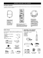 9
9
-
 10
10
-
 11
11
-
 12
12
-
 13
13
-
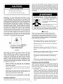 14
14
-
 15
15
-
 16
16
-
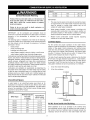 17
17
-
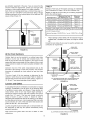 18
18
-
 19
19
-
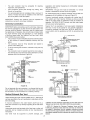 20
20
-
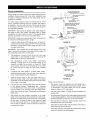 21
21
-
 22
22
-
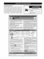 23
23
-
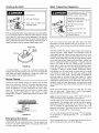 24
24
-
 25
25
-
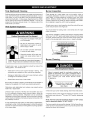 26
26
-
 27
27
-
 28
28
-
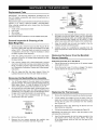 29
29
-
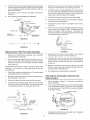 30
30
-
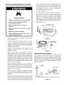 31
31
-
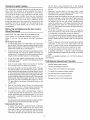 32
32
-
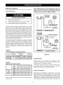 33
33
-
 34
34
-
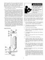 35
35
-
 36
36
-
 37
37
-
 38
38
-
 39
39
-
 40
40


Kenmore 153.339572 User manual
- Category
- Water heaters & boilers
- Type
- User manual
Ask a question and I''ll find the answer in the document
Finding information in a document is now easier with AI
Related papers
-
Kenmore 153.33262 User manual
-
-
Sears 153.33262 User manual
-
Kenmore POWER MISER 9 153.339572 Owner's manual
-
-
-
-
-
-
Other documents
-
Rheem XG40T12DU36U0 User manual
-
 AO Smith GVR Series User manual
-
State Industries 317998-002 User manual
-
A.O. Smith Effex GAHH-40 User manual
-
A.O. Smith GAHH Installation Instructions And Use & Care Manual
-
-
Rheem XG40T12EN38U0 User manual
-
Whirlpool UG2F4040T3NV EST User manual
-
-
Rheem XG40S12DM40U0W User manual
