Page is loading ...

© LINDY ELECTRONICS LIMITED & LINDY-ELEKTRONIK GMBH - FIRST EDITION (August 2003)
KVM Extender C5 Series
User Manual English
LINDY Art No. 39390 (C5 Remote + Local Unit)
LINDY Art No. 39391 (C5 Remote Unit Only)
LINDY Art No. 39389 (Skew Compensator Unit)
LINDY Art No. 39388 (Rack mount chassis)
LINDY Art No. 39386 (Power Distribution module)

English Manual
LINDY KVM Extender C5 Series Installation and Use page 2
About this manual
LINDY KVM Extender C5 Series - Installation and Use www.lindy.com
First edition (October 2003)
(c) 2003 LINDY Computer Connection Technology.
All rights reserved. Whilst every precaution has been taken in the preparation of this manual, LINDY Electronics Ltd
assumes no responsibility for errors or omissions. Neither is any liability assumed for damages resulting from the
use of the information contained herein. We reserve the right to change the specifications, functions and circuitry of
the product without notice.
Safety Information
• For use in dry, oil free indoor environments only.
• Warning - live parts contained within the power adaptor.
• No user serviceable parts within power adaptor - do not dismantle
• Plug the power adaptor into a socket outlet close to the Extender C5 unit that it is powering.
• Replace the power adaptor with a manufacturer approved type only.
• Do not use the power adaptor if the power adaptor case becomes damaged, cracked or broken or if you
suspect that it is not operating properly.
• If you use a power extension cord with the Extender C5, make sure the total ampere rating of the devices
plugged into the extension cord does not exceed the cord’s ampere rating. Also, make sure that the total
ampere rating of all the devices plugged into the wall outlet does not exceed the wall outlet’s ampere
rating.
Warranty information
LINDY warrants that this product shall be free from defects in workmanship and materials for a period of three
years from the date of original purchase. If the product should fail to operate correctly in normal use during the
warranty period, LINDY will replace or repair it free of charge. Any faulty items are to be returned to LINDY at the
owner’s expense. No liability can be accepted for damage due to misuse or circumstances outside LINDY’s control.
Also, LINDY will not be responsible for any loss, damage or injury arising directly or indirectly from the use of this
product. LINDY’s total liability under the terms of this warranty shall in all circumstances be limited to the
replacement value of this product. This warranty goes on top of any applicable legal regulation and does not limit
any customer rights compared to the legal regulations.
Trademarks
All trademarks mentioned in this manual are acknowledged to be the property of the respective trademark owners.
Compaq is a registered trademark of Compaq Computer Corporation.
Hewlett-Packard is a registered trademark of Hewlett-Packard.
IBM, PC/AT, PS/2, RS/6000 and ThinkPad are registered trademarks of International Business Machines
Corporation.
Microsoft and Windows are registered trademarks, and IntelliMouse is a trademark of Microsoft Corporation.
Logitech, MouseMan+ and Pilot Mouse+ are trademarks of Logitech Inc.
Velcro is a trademark of Velcro USA Inc.

English Manual
LINDY KVM Extender C5 Series Installation and Use page 3
Radio Frequency
A Category 5 (or better) twisted pair cable must be used to connect the LINDY Extender C5 units in order to
maintain compliance with radio frequency energy emission regulations and ensure a suitably high level of immunity
to electromagnetic disturbances.
All other interface cables used with this equipment must be shielded in order to maintain compliance with radio
frequency energy emission regulations and ensure a suitably high level of immunity to electromagnetic
disturbances.
European EMC directive 89/336/EEC
This equipment has been tested and found to comply with the limits for a class A computing device in accordance
with the specifications in the European standard EN55022. These limits are designed to provide reasonable
protection against harmful interference. This equipment generates, uses and can radiate radio frequency energy
and if not installed and used in accordance with the instructions may cause harmful interference to radio or
television reception. However, there is no guarantee that harmful interference will not occur in a particular
installation. If this equipment does cause interference to radio or television reception, which can be determined by
turning the equipment on and off, the user is encouraged to correct the interference with one or more of the
following measures: (a) Reorient or relocate the receiving antenna. (b) Increase the separation between the
equipment and the receiver. (c) Connect the equipment to an outlet on a circuit different from that to which the
receiver is connected. (d) Consult the supplier or an experienced radio / TV technician for help.
FCC Compliance Statement (United States)
This equipment generates, uses and can radiate radio frequency energy and if not installed and used properly, that
is, in strict accordance with the manufacturer’s instructions, may cause interference to radio communication. It has
been tested and found to comply with the limits for a class A computing device in accordance with the
specifications in Subpart J of part 15 of FCC rules, which are designed to provide reasonable protection against
such interference when the equipment is operated in a commercial environment. Operation of this equipment in a
residential area may cause interference, in which case the user at his own expense will be required to take
whatever measures may be necessary to correct the interference. Changes or modifications not expressly
approved by the manufacturer could void the user’s authority to operate the equipment.
Canadian Department of Communications RFI statement
This equipment does not exceed the class A limits for radio noise emissions from digital apparatus set out in the
radio interference regulations of the Canadian Department of Communications.
Le présent appareil numérique n’émet pas de bruits radioélectriques dépassant les limites applicables aux
appareils numériques de la classe A prescrites dans le règlement sur le brouillage radioélectriques publié par le
ministère des Communications du Canada.

English Manual
LINDY KVM Extender C5 Series Installation and Use page 4
Contents
1. Introduction.....................................................................................................6
1.1 LINDY KVM Extender C5 features..................................................................................7
1.2 Product information .........................................................................................................8
1.3 Package contents............................................................................................................11
2. Installation of the KVM Extender C5 Junior..................................................13
2.1 What you will need .........................................................................................................13
2.2 Mounting the C5 KVM .....................................................................................................13
2.3 Connecting your devices ................................................................................................14
2.4 Configuring your PC........................................................................................................16
2.5 Configuring the C5 KVM..................................................................................................16
2.6 Setting the option switches .............................................................................................16
2.7 Setting the video compensation manually ......................................................................20
2.8 Special functions and setting user configurable options ................................................22
2.9 Summary of C5 KVM functions and options ..................................................................23
2.10 Other useful installation information .............................................................................24
2.11 Hot plugging the C5 KVM into running systems and re-enabling
disconnected PS/2 CPU mouse connections .......................................................................24
2.12 Using the Extender C5 KVM/R with LINDY Switch Pro KVM switches ........................26
3. Rack mounting C5 products in the 19 inch rack mount chassis................27
3.1 Mounting C5-Series modules into the rack mount chassis...............................................27
3.2 Installing the rack mountable power distribution module ...............................................28
3.3 Blanking plates for the 19 inch rack mount chassis .......................................................28

English Manual
LINDY KVM Extender C5 Series Installation and Use page 5
4. Using the Extender C5 .................................................................................29
4.1 Power on status ..............................................................................................................29
4.2 C5 KVM indicator lights ..................................................................................................29
4.3 Keyboard NUM, CAPS and SCROLL lock indicators .....................................................29
4.4 Keyboard hotkey control .................................................................................................30
4.5 Entering and exiting video compensation / configuration mode .....................................31
4.6 Setting and using the security password ........................................................................31
4.7 Querying the Extender C5’s firmware version ................................................................32
5. Extender C5 configuration options ...............................................................33
5.1 Resetting all configuration options to their default state .................................................33
5.2 Setting a mouse signalling protocol.................................................................................33
6. Configuring and using the skew compensator ............................................34
6.1 What is the skew compensator and why is it needed? ..................................................34
6.2 Can I predict if a skew compensator will be needed? ....................................................34
6.3 Correcting colour split .....................................................................................................34
6.4 Reporting the cable skew and configuring the skew compensator ................................36
6.5 Setting up the skew compensator manually ...................................................................38
7. Upgrading the Extender C5’s flash memory.................................................39
Appendices
A – Cables and connector specifications ..............................................................................42

English Manual
LINDY KVM Extender C5-Series Installation and Use page 6
1. Introduction
Thank you for purchasing this product from the LINDY C5 Series of KVM Extenders. This manual covers the
following products –
LINDY KVM Extender C5 Junior Part No. 39390
LINDY KVM Extender C5 Remote Unit Part No. 39391
LINDY KVM Extender C5 Skew Compensator Unit Part No. 39389
LINDY KVM Extender C5 Rack Mount Chassis Part No. 39388
LINDY KVM Extender C5 Power Distribution Module Part No. 39386
The KVM Extender C5 Junior is designed to transfer keyboard, video, and mouse signals up to 200 metres over
Category 5 (or higher specification) twisted pair cable. The KVM Extender C5 consists of a transmitter (local) and a
receiver (remote) unit that are connected together by a twisted pair cable. The remote unit connects to your
keyboard, monitor and mouse and the local unit connects to the computer system that is to be controlled.
The optional C5 - Series skew compensator, rack mount chassis and power distribution module may be used
together with your KVM Extender C5 Junior
Throughout this document, the LINDY KVM Extender
C5 Junior is commonly abbreviated to C5 KVM.

English Manual
LINDY KVM Extender C5 Series Installation and Use page 7
1.1 LINDY KVM Extender C5 Junior features
• Enables a keyboard, monitor, and mouse to be located up to 200 metres from a computer or KVM switch
• Uses a single Category 5 (or better) twisted pair cable to carry all the keyboard, video and mouse signals
• The C5 KVM product is part of a family of complimentary extender products that are designed to meet a wide
range of KVM extension requirements
• Supports high bandwidth monitors at resolutions up to 1600 x 1280
• Includes CPU connection cable for easy installation
• The local module of the C5 KVM may be neatly rack mounted in the C5 - Series 19-inch rack mount chassis.
Other C5 - Series products may also be mounted in this chassis. Each 2U high chassis will house up to 16
modules
• Supports Microsoft IntelliMouse, IntelliMouse Explorer and other common wheel mice
• Fine user-adjustable video compensation enables the video quality to be maximised for any given length of
cable. Supports automatic and manual video compensation (compensation mode selectable by option switch)
• In manual compensation mode, the video compensation only needs to be adjusted once during setup. The
chosen compensation setting is retained in EEPROM memory even when the C5 KVM is powered off
• In automatic compensation mode, the video compensation will be automatically adjusted every time that the C5
KVM is powered on or reset
• An optional C5 - Series skew compensator unit is available to compensate for the colour skew that is
introduced by using longer lengths of certain types of Category 5e and 6 cable. The C5 KVM reports the cable
skew present in your installation and (optionally) the required skew compensation settings
• Mixed AT/PS2 keyboards and PS2/RS232 mice supported as standard
• Keyboard data is kept in its native format ensuring the additional keys on enhanced keyboards are supported
• Password security prevents unauthorised use
• Supports keyboard modes 1,2 and 3 and mouse prompt and stream modes for maximum compatibility
• Flash upgradeable via the keyboard ports.
• Power / activity indicators confirm correct operation
• Robust metal case ensures good shielding and video quality
• 19 inch rack mount kit available
• Supports IBM PC compatibles, Alpha, SGI and RS6000 computers
• “Transparent” mode enables extender to be used to link together most cascaded KVM switch systems
• Uses patent pending technology

English Manual
LINDY KVM Extender C5 Series Installation and Use page 8
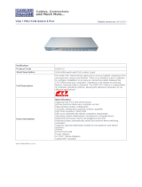
1.2 Product information
Figure 1 – C5-Series KVM local transmitter
Figure 2 – C5-Series KVM remote receiver

English Manual
LINDY KVM Extender C5 Series Installation and Use page 9
Figure 3 – C5-Series skew compensator unit
Figure 4 – C5-Series rack mount chassis and securing plates
19 inch rack mount chassis
Rack securing plate
M3 pan head screw
for fixing security
plate to the rack
mount chassis
2 x M3 counter sunk
screws for fixing
security plate to C5
Series module

English Manual
LINDY KVM Extender C5-Series Installation and Use page 10
Figure 5 – C5-Series power distribution module

English Manual
LINDY KVM Extender C5-Series Installation and Use page 11
1.3 Package contents
The LINDY C5-Series KVM package (Part No. 39390)
The LINDY C5-Series KVM remote receiver package contents (Part No. 39391)
The LINDY C5-Series skew compensation unit package contents (Part No. 39389)
The LINDY C5-Series rack mount chassis (Part No. 39388)
Quantity Description
1 KVM Extender C5 Junior local transmitter unit
1 KVM Extender C5 Junior remote receiver unit
1 Instruction manual
1 Power adaptor for the remote receiver unit
1 Cable to connect the local unit to a computer or KVM switch
8 Self-adhesive rubber feet
Quantity Description
1 KVM Extender C5 Junior remote receiver unit
1 Instruction manual
1 Power adaptor for the remote receiver unit
4 Self-adhesive rubber feet
Quantity Description
1 Skew compensator unit
1 Instruction manual
4 Self-adhesive rubber feet
Quantity Description
1 Rack mount chassis
1 Instruction manual

English Manual
LINDY KVM Extender C5-Series Installation and Use page 12
The LINDY C5-Series rack mount securing and blanking plates
The LINDY C5-Series rack mountable power distribution module package contents
(Part No. 39386)
Quantity Description
1 Rack mount securing plate
2 Counter-sunk screws for fixing the plate to the module
1 Pan head screw for fixing the plate to the rack mount chassis
Quantity Description
1 Power distribution module
1 Power adaptor (5V, 2.5A)
4 Short patch cables
1 Instruction manual
1 Rack mount securing plate for power distribution module
2 Counter-sunk screws for fixing the plate to the PDM module
1 Pan head screw for fixing the plate to the rack mount chassis

English Manual
LINDY KVM Extender C5-Series Installation and Use page 13
2. Installation of the KVM Extender C5
2.1 What you will need
• A category 5 (or better) twisted pair cable of the required length to connect the C5 KVM local and remote units
together. These cables contain 4 pairs of twisted wires. Specifications and recommended cable types are given
in appendix A. The C5 KVM supports cable lengths up to 200 metres. Structured wiring within buildings may
also be used together with suitable patch cables but the number of cable connections should be kept to a
minimum to maximise signal quality.
• Cables to connect the C5 KVM local unit to your computer. A two metre connection cable is provided with the
C5 KVM. The cable may be extended using standard KVM extension cables. Cable specifications are given in
appendix A.
• A monitor with a standard VGA/SVGA (15 pin) connector that will work when connected directly to your
computer. C5 KVM supports low and high resolution monitors.
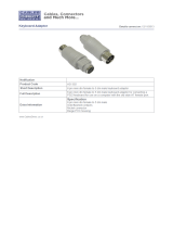
• A standard AT or PS/2 style keyboard. If you are using an AT keyboard with a 5 pin connector you may
connect this to the C5 KVM using a standard AT to PS/2 keyboard adaptor.
• A PS/2 style two or three button Microsoft or Logitech compatible mouse or a Microsoft IntelliMouse
compatible mouse.
(The C5 KVM supports ‘Internet Mice’ that are compatible with the Microsoft IntelliMouse. These are fitted with
a wheel or other scroll control and sometimes have additional buttons. Examples are: Microsoft IntelliMouse,
Logitech Pilot Mouse+, Logitech MouseMan+, Genius NetMouse and Genius NetMouse Pro.)
• A suitable mouse driver for your PC(s). Supported types are:
- PS/2 or RS232 two button mouse driver (any manufacturer).
- Microsoft mouse driver (including IntelliMouse).
- Logitech mouse driver (including two button, three button and wheel mouse)
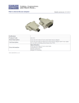
Use of PS/2 and RS232 style mice with the C5 KVM - The mouse connections from the C5 KVM to PCs support
either a PS/2 or an RS232 mouse. The C5 KVM automatically converts from the PS/2 mouse commands to RS232
serial mouse commands. Serial mice types are selected by using an adaptor as described in appendix A. The C5
KVM will operate without a mouse connected if you do not wish to use one.
2.2 Mounting the C5 KVM
The C5 KVM has been designed to be used either on a desktop or mounted in a 19 inch rack. If you wish to use
the C5 KVM on a desktop then you will need to stick the self-adhesive rubber feet onto the underside of each C5
KVM module (one is supplied for each corner).
If the C5 KVM is to be mounted in a 19 inch rack then you will need the optional C5 series rack mounting chassis
(Part No. 39388) and a rack securing plate for each local module that you wish to rack mount (Part No. 39360)
The C5 KVM may also be mounted on a suitable vertical surface, such as the side of a desk, with the use of strong
Velcro strips.

English Manual
LINDY KVM Extender C5-Series Installation and Use page 14
2.3 Connecting your devices
Ensure that the power adaptor is disconnected from the C5 KVM and that all the devices which are to be attached
are switched off. Connect your devices to the C5 KVM as shown in figure 6. Ensure that the cables are no longer
than the maximum cable lengths specified in appendix A. Any unused computer or peripheral connections can be
left unconnected. To connect computers with serial mouse connections and AT style keyboard connections you will
need to purchase adaptors. Please refer to appendix A for cable specifications.
The C5 KVM is now ready for use and will start to operate as soon the local and remote units are both powered
on. There is no requirement to switch the C5 KVM units on in any defined order. The C5 KVM local unit draws its
power from the connected computer via the keyboard cable. However, if you are connecting to a computer using
cables that are longer than 5 metres or are connecting to a lower powered device, such as some types of
keyboard/video/mouse switch, an optional power adaptor may be required. When using the optional power adaptor,
ensure that it is connected to the mains and powering the C5 KVM before you switch on the connected computers.
Under these circumstances, failure to switch the C5 KVM and computers on in the correct order can lead to the
mouse and/or keyboard not being recognised by the computers when they are switched on.
PS/2 to AT keyboard
adaptor (Part No. 70130)
PS/2 to RS232 mouse
adaptor (Part No. 70058)
Connects to
C5 KVM local
transmitter
Cable supplied with C5 KVM Connects to computer

English Manual
LINDY KVM Extender C5-Series Installation and Use page 15
REMOTE
LOCAL
Figure 6 – A typical C5-KVM extender application

English Manual
LINDY KVM Extender C5-Series Installation and Use page 16
2.4 Configuring your PC (s)
Configure your PC in the same way that you would if your keyboard, mouse, speakers, microphone and monitor
were all connected directly to your PC, but bearing in mind the following points:
• C5 KVM emulates Microsoft compatible serial, IntelliMouse and PS/2 mice, so ensure that your PC software is
configured for a Microsoft mouse of the correct type. Refer to the list of supported drivers in section 2.1.
• C5 KVM supports VGA/SVGA/XGA/XGA2 type monitors, but does not support the automatic detection features
available with some ‘plug and play’ monitors and video cards. If you have this type of video card and monitor,
you should select the video mode manually instead of relying upon the automatic detection feature.
2.5 Configuring the C5 KVM
The C5 KVM is supplied in a default state that is suitable for most applications. By default, the automatic
compensation mode is selected. In this mode the video compensation amplifiers will be automatically adjusted to
suit the twisted pair cable whenever the C5 KVM is switched on. Some users may wish to manually fine tune the
video compensation because the perfect adjustment for any given length of cable is subjective and depends upon
personal preference. If manual compensation is selected then the video only needs to be compensated once
during setup as the compensation value is stored by the C5 KVM and retained even when the power is off.
The KVM Extender C5 Junior is configured using the following:
1. Option switches (see section 2.6)
The option switches on the side of the C5 KVM select automatic or manual video compensation mode and the
keyboard hotkey combination that is used to access video compensation / configuration mode. They also control
some other hardware related functions.
2. Video compensation / configuration mode (see section 2.7)
This mode is entered by typing the hotkey combination (selected using the option switches) on the keyboard
attached to the remote receiver. Once within video compensation / configuration mode you can adjust the video
compensation and select other options using the keyboard. The selected options are saved and stored in the
remote unit when you exit compensation / configuration mode.
2.6 Setting the option switches
The option switches on the side of the C5 KVM remote and local units are used to select operating options. The
switches are continuously read by the C5 KVM and may be changed whilst the C5 KVM is powered on. The default
setting (all switches OFF) is suitable for most installations. The switches are shown in figures 7 and 8 and have
the following functions.
REMOTE unit – Switch 1
Set this switch to the OFF position for normal operation. This switch is used to set the C5 KVM remote unit into
upgrade mode so that new firmware can be downloaded into its flash program memory.
REMOTE unit – Switches 2 and 3
These switches select the hotkey combinations that are recognised by the C5 KVM. The chosen hotkey
combinations are used to enter compensation / configuration mode, lock the C5 KVM and disable the C5 KVM’s
video.

English Manual
LINDY KVM Extender C5-Series Installation and Use page 17
REMOTE unit – Switch 4
This switch is used to select the required video compensation mode. When the switch is in the OFF position,
automatic video compensation is selected. In automatic compensation mode, the C5 KVM will check the length of
twisted pair cable linking the local and remote units when it is powered on. It will then adjust the video
compensation amplifiers. In manual compensation mode, the video compensation setting may be adjusted by the
user.
LOCAL unit – Switch 1
Set this switch to the OFF position for normal operation. This switch is used to set the C5 KVM local unit into
upgrade mode so that new firmware can be downloaded into its flash program memory.
LOCAL unit – Switch 2
This switch sets “transparent mode” operation. This mode is useful if the C5 KVM is to be used to linked to a KVM
switch. Cascaded KVM switches often use undocumented data to signal special conditions. In transparent mode
the C5 KVM will enable this undocumented data to be transferred between devices.
LOCAL unit – Switch 3
If this switch is set to the ON position then the remote unit will go directly into compensation / configuration mode
at power on. This enables a password locked remote unit to be reset. See section 4.6 for further details
LOCAL unit – Switch 4
This switch may be used to reset the local unit without disconnecting the power. In the OFF position the C5 KVM
will operate normally. In the ON position the C5 KVM will suspend all operation and reset itself to the power off
condition. Cycling the switch from the OFF position to the ON position and back to the OFF position again will
perform a reset without having to disconnect the computer connection cable.

English Manual
LINDY KVM Extender C5-Series Installation and Use page 18
Figure 7 – C5 KVM remote
module option switches

English Manual
LINDY KVM Extender C5-Series Installation and Use page 19
Figure 7 – C5 KVM local
module option switches

English Manual
LINDY KVM Extender C5-Series Installation and Use page 20
2.7 Setting the video compensation manually
The C5 KVM incorporates fine video compensation amplifiers to maximise the picture quality for any given length of
twisted pair cable. The C5 KVM can be set to automatically adjust the compensation amplifiers to match the cable
or you can adjust the amplifiers manually. Automatic compensation is enabled by setting option switch 4 on the
remote unit to the OFF position. Manual compensation is selected if switch 4 is in the ON position. The best video
compensation setting is often a matter of personal preference and so for the best picture quality we recommend
that you fine tune the amplifiers manually. To do this use the following procedure.
STEP 1
Enter video compensation mode by pressing the HOTKEYS together with
f on the keyboard connected to the
remote receiver unit. The HOTKEYS are those that were set using the option switches (CTRL + SHIFT by default).
For example, assuming the default hotkeys, press these keys together:
b j f
STEP 2
The C5 KVM will now be in compensation adjustment mode. This is indicated by the NUM, CAPS and SCROLL
lock lights on your keyboard. These will flash in sequence at a rate that indicates the level of compensation: a slow
rate of flash indicates a compensation setting suitable for short lengths of twisted pair cable and a fast rate of flash
indicates a compensation setting that is suitable for long lengths of twisted pair cable.
/