Simplicity 040545-00 Installation guide
- Category
- Power generators
- Type
- Installation guide

™
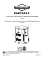
Installation and Operation Manual
10kW
Single Phase Air-Cooled
Standby Generator System
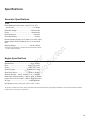
This generator is rated in accordance with UL (Underwriters Laboratories) 2200 (stationary engine generator
assemblies) and CSA (Canadian Standards Association) standard C22.2 No. 100-4 (motors and generators).
© Briggs & Stratton, LLC.
All rights reserved.
80020098USCN
Revision D
Not for
Reproduction

2
Thank you for purchasing this quality-built Briggs & Stratton® home generator. We are pleased that you’ve
placed your confidence in the Briggs & Stratton brand. When operated and maintained according to the
instructions in the operator’s manual, your home generator will provide many years of dependable service.
This manual contains safety information to make you aware of the hazards and risks associated with residential
generator systems and how to avoid them. This generator system is designed and intended only for use as an
optional home standby system that provides an alternate source of electric power and to serve loads such as
heating, refrigeration systems, and communication systems that, when stopped during any power outage, could
cause discomfort or inconvenience. Save these original instructions for future reference.
This generator system requires professional installation before use. The installer should follow the
instructions completely.
Where to Find Us
You never have to look far to find support and service for your generator. Consult your Yellow Pages. There are
many Briggs & Stratton authorized service dealers worldwide who provide quality service. You can also contact
Briggs & Stratton Customer Service by phone at 800-732-2989 between 8:00 AM and 5:00 PM CT., or click on
Find a Dealer at BRIGGSandSTRATTON.COM, which provides a list of authorized dealers.
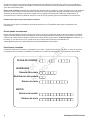
For Future Reference
Please fill out the information below and keep with your receipt to assist in unit identification for future purchase
issues.
Not for
Reproduction

3
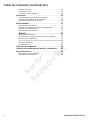
Table Of Contents
Safety Rules ....................................5
Important Safety Instructions ............................... 5
Safety Symbols and Meanings.............................. 5
Installation .....................................8
Home Owner Responsibilities .............................. 8
Installing Dealer/Contractor Responsibilities................... 8
Cold Weather Kit ......................................... 9
Unpacking Precautions .................................... 9
Delivery Inspection ....................................... 9
Shipment Contents ....................................... 9
Generator Placement .................................... 10
Placement of Standby Generator to ........................ 11
REDUCE THE RISK OF CARBON MONOXIDE POISONING ... 11
REDUCE THE RISK OF FIRE ............................. 13
Other Location Requirements.............................. 14
Standard NFPA 37 Requirements and Testing................ 14
Electrical and Fuel Inlet Locations .......................... 15
Lifting the Generator ..................................... 16
Concrete Anchoring of Unit................................ 16
Access Panels .......................................... 17
The Gaseous Fuel System ................................ 19
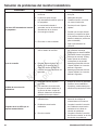
Fuel Factors ............................................ 20
Fuel Consumption . . . . . . . . . . . . . . . . . . . . . . . . . . . . . . . . . . . . . . . 22
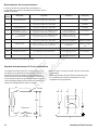
System Connectors...................................... 23
Communication Connections .............................. 24
Generator AC Connection System.......................... 24
Grounding the Generator ................................. 25
Power Connections from Generator to Transfer Switch......... 25
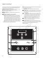
System Control Board.................................... 26
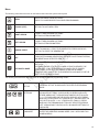
Menu ................................................. 27
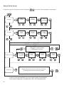
General Set Up Screen................................... 28
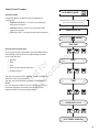
Control Panel Prompts ................................... 29
Advanced Settings Screen ................................ 30
Service Code Detection System ........................... 31
Final Installation Considerations ........................... 31
Initial Start-up (No Load).................................. 32
Operation .....................................33
Automatic Operation Sequence ............................ 33
Setting Exercise Timer ................................... 33
Wireless Monitor (Optional) ............................... 34
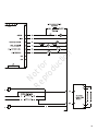
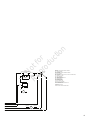
Schematic / Wiring Diagrams.....................39
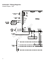
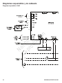
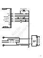
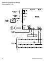
Schematic Diagram - 10kW ............................... 39
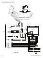
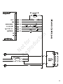
Wiring Diagram - 10 kW .................................. 41
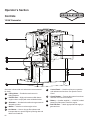
Operator’s Section..............................43
Controls.......................................43
Access Panels .......................................... 44
Operation .....................................46
Important Owner’s Considerations.......................... 46
Automatic Operation ..................................... 47
Setting Exercise Timer ................................... 47
Not for
Reproduction

4
Maintenance ...................................48
Servicing the System..................................... 48
Service Code Detection System ........................... 48
Maintenance Schedule . . . . . . . . . . . . . . . . . . . . . . . . . . . . . . . . . . . 50
Generator Maintenance .................................. 50
Battery ................................................ 51
Engine Maintenance ..................................... 52
Fuel System Inspection and Maintenance ................... 55
Service Spark Plugs ..................................... 56
Clean Air Cooling System and Oil Cooler Fins ................ 56
When Calling for Assistance............................... 56
Storage................................................ 56
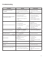
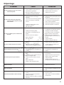
Troubleshooting ...............................57
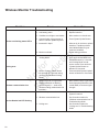
Wireless Monitor Troubleshooting ................58
Specifications..................................59
Table Of Contents (Continued)
Not for
Reproduction

5
Safety Rules
SAVE THESE INSTRUCTIONS - This manual contains
important instructions that should be followed during
installation and maintenance of the generator and
batteries.
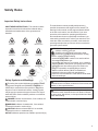
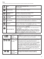
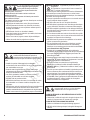
Safety Symbols and Meanings
The safety alert symbol indicates a potential personal
injury hazard. A signal word (DANGER, WARNING, or
CAUTION) is used with the alert symbol to designate a
degree or level of hazard seriousness. A safety symbol
may be used to represent the type of hazard. The signal
word NOTICE is used to address practices not related to
personal injury.
DANGER indicates a hazard which, if not avoided, will
result in death or serious injury.
WARNING indicates a hazard which, if not avoided,
could result in death or serious injury.
CAUTION indicates a hazard which, if not avoided,
could result in minor or moderate injury.
NOTICE addresses practices not related to personal injury.
Important Safety Instructions
WARNING The engine exhaust from this product contains
chemicals known to the State of California to cause cancer, birth
defects, or other reproductive harm.
WARNING Certain components in this product and related
accessories contain chemicals known to the State of California
to cause cancer, birth defects, or other reproductive harm. Wash
hands after handling.
The manufacturer cannot possibly anticipate every
possible circumstance that might involve a hazard. The
warnings in this manual, and the tags and decals affixed
to the unit are, therefore, not all-inclusive. If you use a
procedure, work method or operating technique that
the manufacturer does not specifically recommend, you
must satisfy yourself that it is safe for you and others. You
must also make sure that the procedure, work method or
operating technique that you choose does not render the
generator system unsafe.
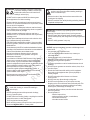
Explosion
Fire
Electrical Shock
Rotating Parts
Hot Surface
Toxic Fumes
Chemical BurnExplosive PressureAuto Start
Lift Hazard
Read Manual
WARNING Running engine gives off carbon monoxide, an
odorless, colorless, poison gas.
Breathing carbon monoxide could result in death,
serious injury, headache, fatigue, dizziness, vomiting,
confusion, seizures, nausea or fainting.
• Operate this product ONLY outdoors in an area that will not
accumulate deadly exhaust gas.
• Keep exhaust gas away from any windows, doors, ventilation
intakes, soffit vents, crawl spaces, open garage doors or other
openings that can allow exhaust gas to enter inside or be
drawn into a potentially occupied building or structure.
• Carbon monoxide detector(s) MUST be installed and
maintained indoors according to the manufacturer’s
instructions/ recommendations. Smoke alarms cannot detect
carbon monoxide gas.
Not for
Reproduction

6
WARNING Unintentional sparking could cause fire or
electric shock resulting in death or serious injury.
WHEN ADJUSTING OR MAKING REPAIRS TO YOUR
GENERATOR
• Disconnect the spark plug wire from the spark plug and place
the wire where it cannot contact spark plug.
WHEN TESTING FOR ENGINE SPARK
• Use approved spark plug tester.
• DO NOT check for spark with spark plug removed.
WARNING Storage batteries give off explosive hydrogen
gas during recharging.
Slightest spark will ignite hydrogen and
cause explosion, resulting in death or
serious injury.
Battery electrolyte fluid contains acid and is extremely caustic.
Contact with battery contents could cause severe chemical
burns.
A battery presents a risk of electrical shock and high short
circuit current.
• DO NOT dispose of battery in a fire. Recycle battery.
• DO NOT allow any open flame, spark, heat, or lit cigarette
during and for several minutes after charging a battery.
• DO NOT open or mutilate the battery.
• Wear protective goggles, rubber apron, rubber boots and
rubber gloves.
• Remove watches, rings, or other metal objects.
• Use tools having insulated handles.
WARNING Generator produces hazardous voltage.
Failure to properly ground generator could result
in electrocution.
Failure to isolate generator from utility power could result
in death or serious injury to electric utility workers due to
backfeed of electrical energy.
• When using generator for backup power, notify utility company.
• DO NOT touch bare wires or bare receptacles.
• DO NOT use generator with electrical cords which are worn,
frayed, bare or otherwise damaged.
• DO NOT handle generator or electrical cords while standing in
water, while barefoot, or while hands or feet are wet.
• If you must work around a unit while it is operating, stand on an
insulated dry surface to reduce the risk of a shock hazard.
• DO NOT allow unqualified persons or children to operate or
service generator.
• In case of an accident caused by electrical shock, immediately
shut down the source of electrical power and contact the local
authorities. Avoid direct contact with the victim.
• Despite the safe design of the residential generator, operating
this equipment imprudently, neglecting its maintenance or
being careless could cause possible injury or death.
• Remain alert at all times while working on this equipment.
Never work on the equipment when you are physically or
mentally fatigued.
• Before performing any maintenance on the generator,
disconnect the battery cable indicated by a NEGATIVE, NEG
or (-) first. When finished, reconnect that cable last.
• After your system is installed, the generator may crank and
start without warning any time there is a power failure. To
prevent possible injury, always set the generator’s system
switch to OFF, remove the service disconnect from the
disconnect box AND remove the 15 Amp fuse BEFORE
working on the equipment.
WARNING Propane and Natural Gas are extremely
flammable and explosive, which could cause
burns, fire or explosion resulting in death or
serious injury.
• Install the fuel supply system according to NFPA 37 and other
applicable fuel-gas codes.
• Before placing the generator into service, the fuel system lines
must be properly purged and leak tested.
• After the generator is installed, you should inspect the fuel
system periodically.
• NO leakage is permitted.
• DO NOT operate engine if smell of fuel is present or other
explosive conditions exist.
• DO NOT smoke around the generator. Wipe up any oil spills
immediately. Ensure that no combustible materials are left in
the generator compartment. Keep the area near the generator
clean and free of debris.
Not for
Reproduction

7
WARNING Starter and other rotating parts could entangle
hands, hair, clothing, or accessories resulting in
serious injury.
• NEVER operate generator without protective housings,
covers, or guards in place.
• DO NOT wear loose clothing, jewelry or anything that could be
caught in the starter or other rotating parts.
• Tie up long hair and remove jewelry.
• Before servicing, remove 15 Amp fuse from control panel and
disconnect Negative (NEG or -) battery cable.
CAUTION Installing the 15 Amp fuse could cause the
engine to start at any time without warning resulting in
minor or moderate injury.
• Observe that the 15 Amp fuse has been removed from the
control panel for shipping.
• DO NOT install this fuse until all plumbing and wiring has been
completed and inspected.
CAUTION Excessively high operating speeds could result
in minor injury.
Excessively low speeds impose a heavy load on generator.
• DO NOT tamper with governed speed. Generator supplies
correct rated frequency and voltage when running at governed
speed.
• DO NOT modify generator in any way.
NOTICE Improper treatment of generator could damage it and
shorten its life.
• Use generator only for intended uses.
• If you have questions about intended use, contact your
authorized dealer.
• Operate generator only on level surfaces.
• Adequate, unobstructed flow of cooling and ventilating air is
critical for correct generator operation.
• The access panels/door must be installed whenever the unit
is running.
• DO NOT expose generator to excessive moisture, dust, dirt, or
corrosive vapors.
• Remain alert at all times while working on this equipment.
Never work on the equipment when you are physically or
mentally fatigued.
• DO NOT start engine with air cleaner or air cleaner
cover removed.
• DO NOT insert any objects through cooling slots.
• DO NOT use the generator or any of its parts as a step.
Stepping on the unit could cause stress and break parts. This
may result in dangerous operating conditions from leaking
exhaust gases, fuel leakage, oil leakage, etc.
• If connected devices overheat, turn them off and disconnect
them from generator.
• Shut off generator if:
-electrical output is lost;
-equipment sparks, smokes, or emits flames;
-unit vibrates excessively.
-unit makes unusual noises.
WARNING Exhaust heat/gases could ignite combustibles
or structures resulting in death or serious injury.
Contact with muffler area could cause burns
resulting in serious injury.
• DO NOT touch hot parts and AVOID hot exhaust gases.
• Allow equipment to cool before touching.
• Exhaust outlet side of weatherproof enclosure must have at
least 5 ft (1.5 m) minimum clearance from any structure, shrubs,
trees or any kind of vegetation.
• Standby generator weatherproof enclosure must be at least 5
ft from windows, doors, any wall opening, shrubs or vegetation
over 12 inches (30.48 cm) in height.
• Standby generator weatherproof enclosure must have a
minimum of 5 ft (1.5 m) overhead clearance from any structure,
overhang or trees.
• DO NOT place weatherproof enclosure under a deck or other
type of structure that may confine airflow.
• USE ONLY flexible steel fuel line provided. Connect provided
fuel line to generator, DO NOT use with or substitute any other
flexible fuel line.
• Smoke detector(s) MUST be installed and maintained indoors
according to the manufacturer’s instructions/ recommendations.
Carbon monoxide alarms cannot detect smoke.
• Keep at least minimum distances shown in Generator
Placement to insure for proper generator cooling and
maintenance clearances.
• It is a violation of California Public Resource Code, Section
4442, to use or operate the engine on any forest-covered,
brush-covered, or grass-covered land unless the exhaust
system is equipped with a spark arrester, as defined in Section
4442, maintained in effective working order. Other states or
federal jurisdictions may have similar laws.
Contact the original equipment manufacturer, retailer, or
dealer to obtain a spark arrester designed for the exhaust
system installed on this engine.
• Replacement parts must be the same and installed in the
same position as the original parts.
Not for
Reproduction

8
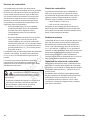
• Read and follow the instructions given in the
operator’s manual.
• Follow a regular schedule in maintaining, caring for
and using your home generator, as specified in the
operator’s manual.
Home Owner Responsibilities
• Read and observe the safety rules.
• Install only an UL approved transfer switch that is
compatible with the generator.
• Read and follow the instructions given in this
installation and start-up manual.
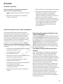
Installing Dealer/Contractor Responsibilities
Installation
This product is only for use as an optional generator system
which provides an alternate source of electric power and
to serve loads such as heating, refrigeration systems, and
communication systems that, when stopped during any
power outage, could cause discomfort or inconvenience.
NOTICE This product does NOT qualify for either an
emergency standby or legally required standby system as
defined by NFPA 70 (NEC).
• Emergency generator systems are intended to
automatically supply illumination, power, or both,
to designated areas and equipment in the event of
failure of the normal supply. Emergency systems may
also provide power for such functions as ventilation
where essential to maintain life, where current
interruption of the normal supply would produce
serious life safety or health hazards.
• Legally Required standby generator systems are
intended to automatically supply power to selected
loads in the event of failure of the normal source
which could create hazards or hamper rescue or fire-
fighting operations.
Every effort has been made to ensure that information in
this manual is accurate and current. However, we reserve
the right to change, alter, or otherwise improve the product
and this document at any time without prior notice.
Only current licensed electrical and plumbing professionals
should attempt home generator system installations.
Installations must strictly comply with all applicable codes,
industry standards, laws and regulations.
• Carbon monoxide detector(s) MUST be installed and
maintained indoors according to the manufacturer’s
instructions/ recommendations. Smoke alarms
cannot detect carbon monoxide gas.
• Smoke detector(s) MUST be installed and maintained
indoors according to the manufacturer’s instructions/
recommendations. Carbon monoxide alarms cannot
detect smoke.
• Installation must strictly comply with all applicable
codes, industry standards, laws, and regulations.
• Allow sufficient room on all sides of the generator for
maintenance and servicing.
Not for
Reproduction

9
After removing the carton, carefully inspect the generator for
any damage that may have occurred during shipment.
If loss or damage is noted at time of delivery, have the
person(s) making delivery note all damage on the freight bill
and affix his signature under the consignor’s memo of loss or
damage. If loss or damage is noted after delivery, separate
the damaged materials and contact the carrier for claim
procedures. Parts damaged in shipping are not warranted.
Delivery Inspection
The home generator system is supplied with:
• Oil (5W30 Synthetic)
• Flexible steel fuel line
• Installation/Operation manual
• Product and emissions warranty booklet
• Spare access keys
• Spare 15 Amp ATO-type fuse
• Battery Tie Down Strap
• Tamper proof plug
Optional Equipment (Sold Seperately)
• Wireless Monitor
Not included:
• Carbon monoxide detector(s)
• Smoke detector(s)
• Starting battery
• Connecting wire and conduit
• Fuel supply valves/plumbing
• Crane, lifting straps, chains or cables
• Two 60” lengths of 3/4” nominal minimum scheduled
40 steel pipe (NOT conduit)
• Torque screwdriver, 5 to 50 inch-pound range
• Voltage/frequency meter
• Two (2) AA batteries for remote wireless monitor
Shipment Contents
Avoid damage from dropping, bumping, collision, etc.
Store and unpack carton with the proper side up, as noted
on the shipping carton.
Unpacking Precautions
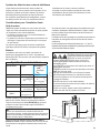
Cold Weather Kit
30°F (-1°C)
If operating the generator below 30°F (-1°C), it is HIGHLY
RECOMMENDED that a Model 6404 Cold Weather Kit be
installed on the 12kW units.
These items are available at your local servicing dealer.
For cold weather areas (below 0°F (-18°C)) it is also
recommended that a BCI, Size 24, wet lead-acid battery
be used of 800 CCA minimum.
If you need more information on this matter, please call
800 732-2989, between 8:00 AM and 5:00 PM CT.
Not for
Reproduction

10
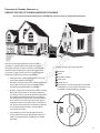
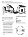
Generator Placement
Before installing the generator, consult with the
homeowner and convey the following requirements, which
must be satisfied before the installation is complete.
There are two equally important safety concerns in regards
to carbon monoxide poisoning and fire. There are also
several general location guidelines that must all be met
before the installation is considered complete.
WARNING Running engine gives off carbon monoxide, an
odorless, colorless, poison gas.
Breathing carbon monoxide could result in death, serious
injury, headache, fatigue, dizziness, vomiting, confusion,
seizures, nausea or fainting.
• Operate this product ONLY outdoors in an area that will not
accumulate deadly exhaust gas.
• Keep exhaust gas away from any windows, doors, ventilation
intakes, soffit vents, crawl spaces, open garage doors or other
openings that can allow exhaust gas to enter inside or be drawn
into a potentially occupied building or structure.
• Carbon monoxide detector(s) MUST be installed and
maintained indoors according to the manufacturer’s
instructions/ recommendations. Smoke alarms cannot detect
carbon monoxide gas.
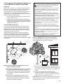
Exhaust Side of the Generator
A
Exhaust outlet side of weatherproof enclosure.
A
Not for
Reproduction

11
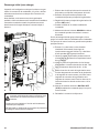
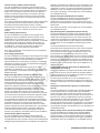
Placement of Standby Generator to
REDUCE THE RISK OF CARBON MONOXIDE POISONING
F
C
D
E
G
B
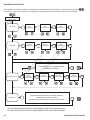
All fossil fuel burning equipment, such as standby
generators, contains carbon monoxide (CO) gas in
the engine exhaust. CO gas is odorless, colorless and
tasteless and is unlikely to be noticed until a person is
overcome. CO gas can kill you so it is required that the
following is included as part of the installation:
• Install generator outdoors in an area that will not
accumulate deadly exhaust gas.
• DO NOT install generator where exhaust gas could
accumulate and enter inside or be drawn into a
potentially occupied building or structure.
• By law it is required in many states to have a Carbon
Monoxide (CO) detector in operating condition in
your home. Carbon monoxide detector(s) (A) MUST
be installed and maintained indoors according to
the manufacturer’s instructions/ recommendations.
A CO monitor is an electronic device that detects
hazardous levels of CO. When there is a buildup of
CO, the monitor will alert the occupants by flashing
visual indicator light and alarm. Smoke alarms
cannot detect CO gas.
• Your neighbor(s) home may be exposed to the
engine exhaust from your standby generator and
must be considered when installing your standby
generator.
• Ensure exhaust gas is kept away from:
windows
doors
ventilation intakes
soffit vents
garage doors
crawl spaces or other openings that can allow
exhaust gas to enter inside or be drawn into a
potentially occupied building or structure.
A
The arrows in the figure below point to POTENTIAL points of entry for Carbon Monoxide Gas.
B
C
D
E
F
G
Not for
Reproduction

12
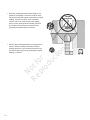
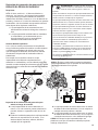
• DO NOT place standby generator in any area where
leaves or debris normally accumulates. Position
standby generator in an area where winds will carry
the exhaust gas away from any potentially occupied
building or structure.
• Direct the standby generator exhaust away from or
parallel to the building or structure. DO NOT direct
the generator exhaust towards a potentially occupied
building, structure, windows, doors, ventilation
intakes, soffit vents, crawl spaces, open garage
doors or other openings where exhaust gas could
accumulate and enter inside or be drawn into a
potentially occupied building or structure.
ENGINE
EXHAUST
STANDBY
GENERATOR
Not for
Reproduction

13
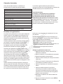
Placement of Standby Generator to REDUCE
THE RISK OF FIRE
Requirements:
NFPA 37 2010, section 4. 1. 4, Engines Located Outdoors.
Engines, and their weatherproof housings if provided,
that are installed outdoors shall be located at least 1.5m
(5 ft) from openings in walls and at least 1.5 m (5 ft) from
structures having combustible walls. A minimum separation
shall not be required where either of the following conditions
exist:
1. The adjacent wall of the structure has a fire
resistance rating of at least 1 hour.
2. The weatherproof enclosure is constructed of
noncombustible materials and it has been demonstrated
that a fire within the enclosure will not ignite combustible
materials outside the enclosure. *
Annex A Explanatory Material
A.4.1.4 (2) Means of demonstrating compliance are by
means of full-scale fire tests or by calculation procedures,
such as those given in NFPA 555, Guide on Methods for
Evaluating Potential for Room Flashover.
To comply with condition 2 above the weatherproof enclosure
has been constructed completely of non-combustible materials
and full-scale fire tests have been conducted to demonstrate
that a fire within the enclosure will not ignite combustible
materials outside the enclosure.
WARNING
Exhaust heat/gases could ignite
combustibles or structures resulting in death, serious
injury and/or property damage.
• Exhaust outlet side of weatherproof enclosure must have
at least 5 ft. (1.5 m) minimum clearance from any structure,
shrubs, trees or any kind of vegetation.
• Standby generator weatherproof enclosure must be at least 5
ft. (1.5 m) from windows, doors, any wall opening, shrubs or
vegetation over 12 inches (30.5 cm) in height.
• Standby generator weatherproof enclosure must have
a minimum of 5 ft. (1.5 m) overhead clearance from any
structure, overhang or trees.
• DO NOT place weatherproof enclosure under a deck or
other type of structure that may confine airflow.
• Use only flexible fuel line provided. Connect provided fuel
line to generator, DO NOT use with or substitute any other
flexible fuel line.
• Smoke detector(s) MUST be installed and maintained
indoors according to the manufacturer’s instructions/
recommendations. Carbon monoxide alarms cannot detect
smoke.
• DO NOT place weatherproof enclosure in manner other
than shown in illustrations.
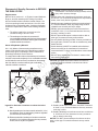
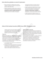
Legend for Generator Locations to reduce the risk of
fire.
A Standby weatherproof enclosure must be at least 5 ft (1.5 m)
from windows, doors, any wall opening, shrubs or vegetation
over 12 inches (30.5 cm) in height.
B Exhaust outlet side of weatherproof enclosure must have
at least 5 ft (1.5 m) minimum clearance from any structure,
shrubs, trees or any kind of vegetation.
C Standby weatherproof enclosure must have a minimum
of 5 feet (1.5 m) overhead clearance from any structure,
overhang or trees.
D Standby Weatherproof enclosure must have a minimum
of 18 inches (45.7 cm) clearance from any structures
with or without a fire rating.
NOTICE DO NOT place weatherproof enclosure under a
deck or other type of covered structure that may confine
airflow.
NOTICE The figures below demonstrate the minimum
installation distances allowed to structures and items
shown in legend.
A
Standby
5 ft (1.5 m)
5 ft (1.5 m)
5 ft (1.5 m)
Exhaust
Direction
18 in.
(45.7 cm) min.
Standby
Exhaust
Direction
5 ft (1.5 m)
A
A
A
B
D
D
C
B A
Not for
Reproduction

14
Requirements:
NFPA 37 2010, section 4. 1. 4, Engines Located Outdoors.
Engines, and their weatherproof housings if provided, that
are installed outdoors shall be located at least 1.5m (5 ft)
from openings in walls and at least 1.5 m (5 ft) from structures
having combustible walls. A minimum separation shall not be
required where either of the following conditions exist:
1. The adjacent wall of the structure has a fire
resistance rating of at least 1 hour.
2. The weatherproof enclosure is constructed
of noncombustible materials and it has been
demonstrated that a fire within the enclosure will not
ignite combustible materials outside the enclosure. *
Annex A Explanatory Material
A.4.1.4 (2) Means of demonstrating compliance are by
means of full-scale fire tests or by calculation procedures,
such as those given in NFPA 555, Guide on Methods for
Evaluating Potential for Room Flashover.
To comply with condition 2, the weatherproof enclosure
has been constructed completely of non-combustible
materials and full-scale fire tests have been conducted to
demonstrate that a fire within the enclosure will not ignite
combustible materials outside the enclosure.
National Fire Protection Association (NFPA) Standard NFPA 37 Requirements and Testing
• Place the standby generator in a prepared location
that is flat and has provisions for water drainage.
• Install the standby generator in a location where
sump pump discharge, rain gutter down spouts, roof
run-off, landscape irrigation, or water sprinklers will
not flood the unit or spray the enclosure and enter
any air inlet or outlet openings.
• Install the standby generator where it will not
affect or obstruct any services (including covered,
concealed and underground), such as telephone,
electric, fuel (natural gas / LPG vapor), irrigation, air
conditioning, cable, septic, sewer, well and so forth.
• Install the standby generator where leaves, grass,
snow, etc will not obstruct air inlet and outlet
openings. If prevailing winds will cause blowing or
drifting, you may need to construct a windbreak to
protect the unit.
Other Location Requirements
Not for
Reproduction

15
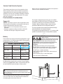
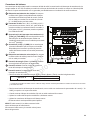
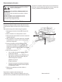
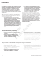
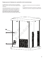
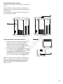
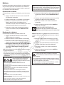
Electrical and Fuel Inlet Locations
The 3/4 inch N.P.T. fuel inlet connector (A) and electrical
inlet location (B) is shown below.
A ½ inch knock-out is provided for the electrical inlet. This
inlet may be enlarged or supplemented to accommodate
a maximum conduit size of 1 ½ inches. Ensure that the
installed conduit(s) enter the unit in the zone (C) shown in
the drawing such that they properly enter the electrical box
and do not interfere with the fully opened roof.
The home generator is supplied with a base that, unless
mandated by local code, does not require a concrete slab.
A
B
C
Not for
Reproduction

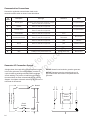
16
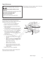
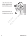
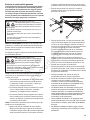
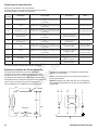
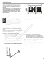
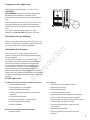
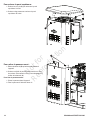
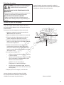
Lifting the Generator
The generator weighs more than 330 pounds (150 kg).
Proper tools, equipment and qualified personnel should be
used in all phases of handling and moving the generator.
Two 60” lengths of 3/4” nominal minimum scheduled 40
steel pipe (A), supplied by the installer, are required to
lift the generator manually. Insert pipes through the lifting
holes (B) located near the unit’s base.
You may also lift the unit using a “hook and hoist” method
attached to the lifting pipes, provided that you use a
spreader bar to ensure that the chains or cables DO NOT
touch the generator’s roof.
WARNING Hazardous Voltage - Contact with power lines
could cause electric shock or burn, resulting in
death or serious injury.
Lifting Hazard / Heavy Object - Could result in
serious injury.
• If lifting or hoisting equipment is used, DO NOT contact any
power lines.
• DO NOT lift or move generator without assistance.
• Use lifting pipes as described in Lifting the Generator.
• DO NOT lift unit by roof as damage to generator will occur.
In areas determined to be hurricane prone, it is
recommended to anchor the standby generator to concrete.
The concrete slab should be at least 3” (76mm) thick and
6” (152mm) longer and wider than the unit [32” (813mm) x
29” (737mm)]. Use 1/4” (6mm) diameter (minimum) by 3”
(76mm) long (minimum) masonry anchor bolts to retain the
unit. There are three 7/16” hole locations (C) in the base of
the generator in which to anchor the unit.
Concrete Anchoring of Unit
C
C
C
NOTICE Unless mandated by local or state code, a
concrete slab is not required.
B
A
22.559” (573mm)
19.016” (483mm)
Not for
Reproduction

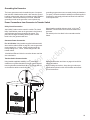
17
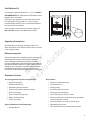
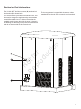
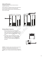
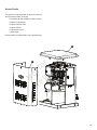
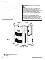
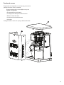
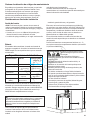
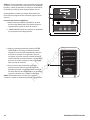
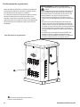
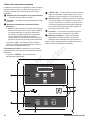
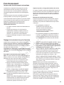
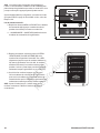
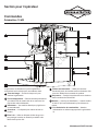
Access Panels
The generator is equipped with an enclosure that has
several access panels, as shown.
Front Panel (A) and roof (B) are used to access:
• Battery Compartment
• Engine Oil Drain Hose
• Engine Oil Filter
• Engine Valve Cover
• Spark Plugs
Each generator is shipped with a set of identical keys.
B
A
B
Not for
Reproduction

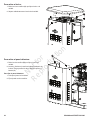
18
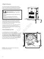
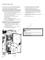
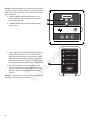
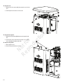
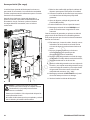
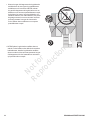
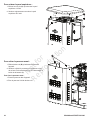
. To remove roof:
1. Remove the five screws (A) that secure the roof to the
unit.
2. Carefully lift and remove roof from unit.
To remove front panel:
1. Remove the two screws (B) that secure the panel to the
unit.
2. Lift and flex panel outward and off base. Use caution
not to damage the battery box (C).
To secure front panel:
1. Place panel in unit.
2. Secure the panel with two screws.
A
A
A
B
C
Not for
Reproduction

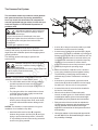
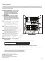
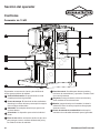
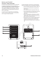
19
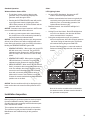
The information below is provided to assist gaseous
fuel system technicians in planning installations.
In no way should this information be interpreted to
override applicable fuel gas codes. Consult with your
local fuel supplier or Fire Marshall if questions or
problems arise.
TO THE INSTALLER: Consult with the generator
owner(s) and convey any technical considerations that
might affect their installation plans before applying these
general guidelines.
The following general rules apply to gaseous fuel
system piping:
WARNING Propane and Natural Gas are extremely
flammable and explosive, which could cause
burns, fire or explosion resulting in death or
serious injury.
• Before placing the generator into service, the fuel system lines
must be properly purged and leak tested.
• No leakage is permitted.
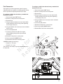
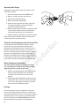
NOTICE The supplied flexible
steel fuel line
is not to be
installed underground or in contact with the ground.
• The entire
flexible
steel fuel line must be visible for
periodic inspection and must not be concealed
within nor contact nor run through any wall, floor, or
partition.
• The piping should be of a material that conforms
to federal and local codes, rigidly mounted and
protected against vibration.
• Piping should be protected from physical damage
where it passes through flower beds, shrub beds,
and other cultivated areas where damage could
occur.
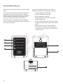
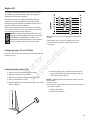
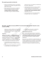
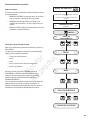
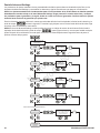
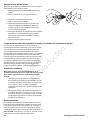
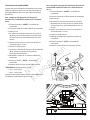
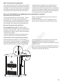
NOTICE The illustration is representative of a typical
installation. Your installation may differ.
• Install the
flexible
steel fuel line (B) (supplied)
between the generator fuel inlet port (A) and rigid
piping to prevent thermal expansion, contraction,
or any standby movement from causing excessive
stress on the piping material.
The Gaseous Fuel System
B
C
E
D
F
A
• A union (C) or flanged connection shall be provided
downstream to permit removal of standby.
• A manometer port should be provided (D). A digital
manometer, P/N 19495, is available at your Briggs &
Stratton service center. When the initial test runs are
completed, the manometer is removed and the port
is plugged. The manometer port permits temporary
installation of a manometer to ensure that the
engine receives the correct fuel pressure to operate
efficiently throughout its operating range.
• Where the formation of hydrates or ice is known to
occur, piping should be protected against freezing.
The termination of hard piping should include a
sediment trap (F) where condensate is not likely to
freeze.
• A minimum of one accessible, approved manual
shutoff valve (E) shall be installed in the fuel supply
line within 6 ft. (180 cm) of the home generator.
• A manual fuel shut-off valve should be installed in
the interior of the building.
• Where local conditions include earthquake,
tornado, unstable ground, or flood hazards, special
consideration shall be given to increase strength
and flexibility of piping supports and connections.
• Piping must be of the correct size to maintain the
required supply pressures and volume flow under
varying generator load conditions with all gas
appliances connected to the fuel system turned on
and operating.
• Use a pipe sealant or joint compound approved for
use with NG/LPG on all threaded fittings to reduce
the possibility of leakage.
WARNING Propane and Natural Gas are extremely
flammable and explosive, which could cause
burns, fire or explosion resulting in death or
serious injury.
• LP gas is heavier than air and will settle in low areas.
• Natural gas is lighter than air and will collect in high areas.
• The slightest spark could ignite these fuels and cause
an explosion.
• DO NOT light a cigarette or smoke.
Not for
Reproduction

20
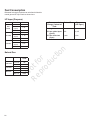
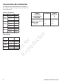
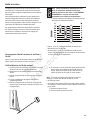
Fuel Pressure
Both LP vapor and natural gas fuel supply pressure at the
generator’s fuel inlet port should be between the following
levels at full load with all gas appliances turned on and
operating.
• NG is 3.5-7” W.C.
• LP is 11-14” W.C.
Ensure that all gas line shutoff valves are OPEN and that
adequate fuel pressure is available whenever automatic
operation is desired.
Power Loss
Air density is less at high altitudes, resulting in less
available engine power. Specifically, engine power will
decrease 3.5% for each 1,000 feet (300 m) above sea
level and 1% for each 10° F (5.6°C) above 77°F (25°C).
Generators located in these conditions must have their
transfer switch adjusted appropriately for this power
decrease. See Automatic Transfer Switch manual on how
to adjust for the power decrease.
Fuel Pipe Sizing
There are numerous on-line or otherwise-published
references for fuel pipe sizing. For example, NFPA 54 -
National Fuel Gas Code, 2006 (Item #: 320-6031-06) is a
common resource.
The installer should consider the specific gravity of gas
and compensate for a nominal amount of restriction from
bends, fittings, etc. If an unusual number of fittings, bends,
or other restrictions are used, refer to federal and local
codes for guidance.
• Installed piping must be properly purged and
leak tested, in accordance with applicable codes
and standards.
Fuel Factors
An important consideration affecting the entire installation
is the type of fuel used by your generator. The system was
factory tested and adjusted using natural gas, but can be
converted to use LP vapor. For proper engine function,
factors that are inherent to each of these fuels, your
location and the duration of possible utility interruptions are
important considerations in the following fuel guidelines:
• Use clean, dry fuel, free of moisture or any
particulate material. Using fuels outside the
following recommended values may cause
performance problems.
• In engines set up to run on propane (LP),
commercial grade HD5 propane with a minimum
fuel energy of 2500 BTUs/ft3 with maximum
propylene content of 5% and butane and heavier
gas content of 2.5% and minimum propane content
of 90% is required.
Natural gas rating will depend on specific fuel but typical
derates are between 10 to 20% off the LP gas rating.
Natural gas or LP engines are certified to operate on
natural or liquid propane gas. The emissions control
system for this engine is EM (Engine Modifications).
WARNING Propane and Natural Gas are extremely
flammable and explosive, which could cause
burns, fire or explosion resulting in death or
serious injury.
• The residential generator is equipped with an automatic safety
gas “fuel shut-off” valve.
• DO NOT operate the equipment if the “fuel shut-off” valve is
missing or inoperative.
Not for
Reproduction
Page is loading ...
Page is loading ...
Page is loading ...
Page is loading ...
Page is loading ...
Page is loading ...
Page is loading ...
Page is loading ...
Page is loading ...
Page is loading ...
Page is loading ...
Page is loading ...
Page is loading ...
Page is loading ...
Page is loading ...
Page is loading ...
Page is loading ...
Page is loading ...
Page is loading ...
Page is loading ...
Page is loading ...
Page is loading ...
Page is loading ...
Page is loading ...
Page is loading ...
Page is loading ...
Page is loading ...
Page is loading ...
Page is loading ...
Page is loading ...
Page is loading ...
Page is loading ...
Page is loading ...
Page is loading ...
Page is loading ...
Page is loading ...
Page is loading ...
Page is loading ...
Page is loading ...
Page is loading ...
Page is loading ...
Page is loading ...
Page is loading ...
Page is loading ...
Page is loading ...
Page is loading ...
Page is loading ...
Page is loading ...
Page is loading ...
Page is loading ...
Page is loading ...
Page is loading ...
Page is loading ...
Page is loading ...
Page is loading ...
Page is loading ...
Page is loading ...
Page is loading ...
Page is loading ...
Page is loading ...
Page is loading ...
Page is loading ...
Page is loading ...
Page is loading ...
Page is loading ...
Page is loading ...
Page is loading ...
Page is loading ...
Page is loading ...
Page is loading ...
Page is loading ...
Page is loading ...
Page is loading ...
Page is loading ...
Page is loading ...
Page is loading ...
Page is loading ...
Page is loading ...
Page is loading ...
Page is loading ...
Page is loading ...
Page is loading ...
Page is loading ...
Page is loading ...
Page is loading ...
Page is loading ...
Page is loading ...
Page is loading ...
Page is loading ...
Page is loading ...
Page is loading ...
Page is loading ...
Page is loading ...
Page is loading ...
Page is loading ...
Page is loading ...
Page is loading ...
Page is loading ...
Page is loading ...
Page is loading ...
Page is loading ...
Page is loading ...
Page is loading ...
Page is loading ...
Page is loading ...
Page is loading ...
Page is loading ...
Page is loading ...
Page is loading ...
Page is loading ...
Page is loading ...
Page is loading ...
Page is loading ...
Page is loading ...
Page is loading ...
Page is loading ...
Page is loading ...
Page is loading ...
Page is loading ...
Page is loading ...
Page is loading ...
Page is loading ...
Page is loading ...
Page is loading ...
Page is loading ...
Page is loading ...
Page is loading ...
Page is loading ...
Page is loading ...
Page is loading ...
Page is loading ...
Page is loading ...
Page is loading ...
Page is loading ...
Page is loading ...
Page is loading ...
Page is loading ...
Page is loading ...
Page is loading ...
Page is loading ...
Page is loading ...
Page is loading ...
Page is loading ...
Page is loading ...
Page is loading ...
Page is loading ...
Page is loading ...
Page is loading ...
Page is loading ...
Page is loading ...
Page is loading ...
Page is loading ...
Page is loading ...
Page is loading ...
Page is loading ...
Page is loading ...
Page is loading ...
Page is loading ...
Page is loading ...
Page is loading ...
-
 1
1
-
 2
2
-
 3
3
-
 4
4
-
 5
5
-
 6
6
-
 7
7
-
 8
8
-
 9
9
-
 10
10
-
 11
11
-
 12
12
-
 13
13
-
 14
14
-
 15
15
-
 16
16
-
 17
17
-
 18
18
-
 19
19
-
 20
20
-
 21
21
-
 22
22
-
 23
23
-
 24
24
-
 25
25
-
 26
26
-
 27
27
-
 28
28
-
 29
29
-
 30
30
-
 31
31
-
 32
32
-
 33
33
-
 34
34
-
 35
35
-
 36
36
-
 37
37
-
 38
38
-
 39
39
-
 40
40
-
 41
41
-
 42
42
-
 43
43
-
 44
44
-
 45
45
-
 46
46
-
 47
47
-
 48
48
-
 49
49
-
 50
50
-
 51
51
-
 52
52
-
 53
53
-
 54
54
-
 55
55
-
 56
56
-
 57
57
-
 58
58
-
 59
59
-
 60
60
-
 61
61
-
 62
62
-
 63
63
-
 64
64
-
 65
65
-
 66
66
-
 67
67
-
 68
68
-
 69
69
-
 70
70
-
 71
71
-
 72
72
-
 73
73
-
 74
74
-
 75
75
-
 76
76
-
 77
77
-
 78
78
-
 79
79
-
 80
80
-
 81
81
-
 82
82
-
 83
83
-
 84
84
-
 85
85
-
 86
86
-
 87
87
-
 88
88
-
 89
89
-
 90
90
-
 91
91
-
 92
92
-
 93
93
-
 94
94
-
 95
95
-
 96
96
-
 97
97
-
 98
98
-
 99
99
-
 100
100
-
 101
101
-
 102
102
-
 103
103
-
 104
104
-
 105
105
-
 106
106
-
 107
107
-
 108
108
-
 109
109
-
 110
110
-
 111
111
-
 112
112
-
 113
113
-
 114
114
-
 115
115
-
 116
116
-
 117
117
-
 118
118
-
 119
119
-
 120
120
-
 121
121
-
 122
122
-
 123
123
-
 124
124
-
 125
125
-
 126
126
-
 127
127
-
 128
128
-
 129
129
-
 130
130
-
 131
131
-
 132
132
-
 133
133
-
 134
134
-
 135
135
-
 136
136
-
 137
137
-
 138
138
-
 139
139
-
 140
140
-
 141
141
-
 142
142
-
 143
143
-
 144
144
-
 145
145
-
 146
146
-
 147
147
-
 148
148
-
 149
149
-
 150
150
-
 151
151
-
 152
152
-
 153
153
-
 154
154
-
 155
155
-
 156
156
-
 157
157
-
 158
158
-
 159
159
-
 160
160
-
 161
161
-
 162
162
-
 163
163
-
 164
164
-
 165
165
-
 166
166
-
 167
167
-
 168
168
-
 169
169
-
 170
170
-
 171
171
-
 172
172
-
 173
173
-
 174
174
-
 175
175
-
 176
176
-
 177
177
-
 178
178
-
 179
179
-
 180
180


Simplicity 040545-00 Installation guide
- Category
- Power generators
- Type
- Installation guide
Ask a question and I''ll find the answer in the document
Finding information in a document is now easier with AI