American Audio AM8505-A User manual
- Category
- Supplementary music equipment
- Type
- User manual
This manual is also suitable for

the speaker specialists
®
OWNER’S
MANUAL
PSW303
PSW404
PSW505
POWERED
SUBWOOFERS

2 Contact Polk Audio Customer Service 1-800-377-7655, [email protected]
IMPORTANT SAFETY INSTRUCTIONS
READ BEFORE OPERATING EQUIPMENT
1. Read these instructions.
2. Keep these instructions.
3. Heed all warnings.
4. Follow all instructions.
5. Do not use this apparatus near water.
6. Clean only with dry cloth.
7. Do not block any ventilation openings. Install in accordance with the
manufacturer's instructions.
8. Do not install near any heat sources such as radiators, heat registers,
stoves, or other apparatus (inlcuding amplifiers) that produce heat.
9. Do not defeat the safety purpose of the polarized or grounding-type plug.
A polarized plug has two blades with one wider than the other. A
grounding type plug has two blades and a third grounding prong. The
wide blade or the third prong are provided for your safety. If the provided
plug does not fit into your outlet, consult an electrician for replacement
of the obsolete outlet.
10. Protect the power cord from being walked on or pinched particularly
at plugs, convenience receptacles, and the point where they exit from
the apparatus.
11. Only use attachments/accessories specified by the manufacturer.
12. Use only with the cart, stand, tripod, bracket, or table specified by the
manufacturer, or sold with the apparatus. When a cart is used use
caution when moving the cart/apparatus combination to avoid injury
from tip-over.
13. Unplug this apparatus during lightning storms or when unused for
long periods of time.
14. Refer all servicing to qualified service personnel. Servicing is required
when the apparatus has been damaged in any way, such as power-supply
cord or plug is damaged, liquid has been spilled or objects have fallen
into the apparatus, the apparatus has been exposed to rain or moisture,
does not operate normally, or has been dropped.
15.
WARNING: To reduce the risk of fire or electric shock, this apparatus
should not be exposed to rain or moisture and objects filled with liquids,
such as vases, should not be placed on this apparatus.
16. To completely disconnect this equipment from the mains, disconnect
the power supply cord plug from the receptacle.
17. The mains plug of the power supply cord shall remain readily operable.

GETTING STARTED
Please inspect your loudspeaker carefully. Notify your Polk dealer if you notice any damage or missing items. Keep the carton and packing
material. It will do the best job of protecting your speaker if it needs to be transported.
Note to PSW505 owners only: Your PSW505 system includes a detachable power cord that’s packaged seperately from the cabinet. Insert female
end into recepticle on amplifier plate and insert polarized AC plug into wall outlet (or power strip) as per safety instructions on inside cover of
this manual.
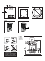
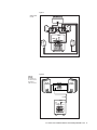
PLACEMENT (FIGURES 1, 2 & 3)
Your PSW Series subwoofer offers many placement options—in an entertainment center, behind furniture, or next to a sofa or chair. It can be
placed anywhere in the room, but you will get the best performance from it when it is on the same side of the room as the front speakers.
Placing it near a wall or in a corner will increase bass loudness. Allow at least 6 inches (15cm) of space between the subwoofer driver and a
wall or obstruction
(Figure 1). The subwoofer should only be placed on its base (Figure 2). It may lie on its side, but NEVER LAY THE SUB-
WOOFER ON THE AMPLIFIER END—THIS WILL DAMAGE THE AMPLIFIER
(Figure 3).
Your powered subwoofer is magnetically shielded for placement near video monitors. Allow at least 18" (45cm) of space between your sub-
woofer and any television. If you notice video distortion or discoloration, immediately move the subwoofer away from the TV and call Polk
Audio Customer Service 800-377-7655 (US & Can), 410-358-3600, 9am-6pm EST, Monday through Friday, or email: [email protected]m.
You’ll find an informative article on “Subwoofer Positioning and Adjustment”
in the set up section at:
http://www.polkaudio.com/home/faqad/
CONNECTING THE SUBWOOFER TO THE SYSTEM— GENERAL
If you elect to use the speaker level inputs, use two-conductor 16 gauge or thicker speaker wires. See your Polk dealer for
wire recommendations.
Note that one of the speaker input terminals on the rear of the speaker is marked red (+) and the other black (-). Make certain that you
connect the wire from the red (+) terminal of your amplifier to the red (+) terminal on your speaker, and the wire from the black
(-) terminal of the amplifier to the black (-) terminal on your speaker. Most wire has some indication (such as color coding, ribbing,
or writing) on one of the two conductors to help maintain consistency. If your subwoofer doesn’t seem to produce much bass, it is
most likely that one of the speaker wires is connected backwards. Double check all connections for correct polarity.
Strip 1/2" (12mm) of insulation from each of the two conductors on both ends to expose the bare wire. Twist the exposed wire of each
conductor to form two un-frayed strands. Connect two conductors to the receiver or amp (refer to the owner’s manual supplied with your
electronics for assistance with proper hookup). Connect the two conductors on the other end of the wire to the speaker terminals. Repeat for
the other channel.
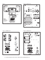
USING PUSH-TAB TERMINALS – PSW303 (FIGURE 4)
Push the plastic tab of one connector to open up the hole. Insert the bare wire into the hole, and release the plastic tab. Repeat this
step for the other terminal.
Make sure that none of the bare wire ends (left & right) touch. Such contact could result in an electrical short and cause your receiver or
amplifier to turn off or malfunction.
USING BINDING POST CONNECTIONS – PSW404 AND PSW505(FIGURE 5)
Unscrew binding post hex nuts several turns. Make sure that none of the bare wire ends touch. Such contact could result in an electrical short
and cause your amplifier or receiver to turn off or malfunction.
RECOMMENDED HOOK-UP METHOD FOR “ SATELLITE” SYSTEMS
SUCH AS POLK RM SERIES SPEAKERS
(FIGURES 6 & 7)
Connect the left and right front speaker outputs of your receiver or amplifier to the speaker level inputs of the powered subwoofer using
speaker wire.
Then, connect the left and right front satellite speakers using speaker wire from the speaker level outputs from the powered subwoofer.
If it is more convenient, parallel wire the subwoofer and front satellites from your receiver (Figure 7).
Connect the Center Channel Speaker directly to the center channel output from your receiver.
Connect the Rear Surround Satellites directly to the rear or surround channel outputs from your receiver.
For accessories and information visit www.polkaudio.com 3

4 Contact Polk Audio Customer Service 1-800-377-7655, [email protected]
RECEIVER SET-UP / BASS MANAGEMENT
All surround receivers allow you to “customize” their performance depending on the size of your speakers. Refer to the owner's manual of your
receiver or surround processor to learn how this is done. To get the best performance from small “satellite/subwoofer” type systems, use the
following settings with the above hook-up method:
Front speakers -- set to “large”
Center speaker -- set to “normal” or “small”
Surround speakers -- set to “small”
Subwoofer -- set to “OFF” or “none.” (We know. Doesn’t make sense, right? Your system obviously has a subwoofer. But really truly, this is the
correct setting for the recommended hook-up method. By setting the front left and right speakers to “Large” and routing them through the sub-
woofer as instructed above, you deliver a full range signal to the subwoofer’s low pass filter. The low pass filter directs low frequencies and to
the subwoofer. Full range signal is passed to the front speakers, for perfect sub/sat blending.)
HOOK-UP METHOD #2 (FIGURE 8)
This method can be used with electronics that include a “SUB OUT” feature (Figure 8). It is not recommended for use with compact sub/sat
systems. Connect a single RCA cable from the “SUB OUT” of your electronics to the LFE input of the subwoofer. This input bypasses the sub-
woofer’s variable low pass filter and relies on the filter built into your electronics. If your “SUB OUT” is an unfiltered signal (check your owner’s
manual), use either left or right “Line Level Input,” to use the low pass crossover in the subwoofer. When using method #2, it is necessary to
adjust the settings of your electronics as follows: Front speakers = large or small depending on their output capabilities; Subwoofer = “ON.”
HOOK-UP METHOD #3 (FIGURE 9)
This method is for use with electronics featuring “PRE OUT” jacks—and may be used as a secondary hook up method for use with compact
satellite speakers such as Polk RM Series. Connect the left and right preamp output from your electronics to the left and right LINE LEVEL input
of the subwoofer. This may require use of RCA “Y” cables (not supplied) to hookup both the subwoofer and your power amplifier. When using
method #3, it is necessary to adjust the settings on your preamp/processor as follows: Front speakers = LARGE; Subwoofer = “OFF” or “NO.”
AC POWER CONNECTION AND AUTO ON/OFF (FIGURES 10, 11 & 12)
These PSW series subwoofers feature auto on/off circuitry, marked “auto” on the power switch, that automatically turns your subwoofer on
when it senses a program signal. When no signal is present, the circuit turns the subwoofer off after a few minutes. If you are concerned
about the brief delay between when the music starts and when the subwoofer turns on, simply leave your subwoofer in the “on” position. When
the power switch is set to “OFF” (PSW303 or PSW404) or “STANDBY” (PSW505) it consumes a low amount of power. If this is a concern, you
may want to leave your PSW system unplugged during extended periods of non use, such as during a vacation.
Note (PSW505 owners only): Your PSW505 has a detachable power cord.
SUBWOOFER ADJUSTMENTS (FIGURES 10, 11 & 12)
Your Powered Subwoofer offers a range of setting options. We recommend the following settings as starting points, but the setti
ngs that are
best for you depend upon your speaker placement, electronics and personal taste. After you’ve become familiar with what the settings do,
experiment with alternate options to find the method that works best for your system setup. You’ll find an informative article on “Subwoofer
Positioning and Adjustment” in the set up section at:
http://www.polkaudio.com/home/faqad/
“ MAKING ADJUSTMENTS” OR “ FINE TUNING” (FIGURES 10, 11 & 12)
• For RM System adjustments please refer to their owners manuals.
• Volume—Adjust by ear using a wide variety of CDs and video sources. Adjust for deep, powerful bass without “boominess.”
• Low Pass—This control adjusts the frequency range over which the subwoofer operates. When using smaller main speakers, the upper
range of the control will probably yield the best results. With larger speakers, the lower end of the control range will probably sound best,
but always let your ear be the final judge. If male vocals sound “thin,” turn this control up until the voice sounds rich but not boomy. If
male vocals sound too “thick” or “chesty,” turn this control down until the voice sounds natural. NOTE: This control does not operate when
the subwoofer is connected with Method #2 (LFE Input).
• Phase Switch—Have someone switch between the two settings while you sit in your favorite listening position. Use music with good bass
and a deep male vocal. When you hear the best balance of deep bass and natural lower octaves of the male voice, you have achieved opti-
mum phase tuning.

For accessories and information visit www.polkaudio.com 5
Q: “ Why does my system hum?”
A: “
Because it doesn’t know the words.”
This is what passes for humor in the audio business. Here’s the real answer: If you have any electrical (50/60Hz) hum in your system you’re
going to hear it clearly as soon as you hook up your subwoofer. Most hum problems are caused by “ground loops.” That is, the electrical grounds
of the components in your system are not at the same electrical potential. A very common ground loop source is cable TV. Disconnect the coaxial
cable from your TV and/or VCR. If the hum goes away, the cable is the ground loop villain. In that case you need a 75 ohm ground loop isolator.
This device attaches to your coaxial cable where it plugs into your VCR (or television). They’re simple to install and usually solve the hum
problem. Find 75 ohm ground loop isolators at your audio dealer, Radio Shack stores, or online at
http://shop.polkaudio.com.
Ground loops and hum can also be the result of faulty electrical wiring in your home. Consult a licensed electrician to evaluate and, if necessary,
repair the AC wiring in your home. Light dimmers also tend to introduce noise into audio systems. Remove them.
If none of our suggestions work for you, contact Polk Audio Customer Service 800-377-7655 (US & Canada), 410-358-3600, 9am-6pm EST,
Monday through Friday, or email: [email protected].
TECHNICAL ASSISTANCE OR SERVICE
If, after following these hook up directions, you experience difficulty, please double-check all wire connections. Should you isolate the problem
to the speaker, contact the authorized Polk Audio dealer where you made your purchase, or call Polk Audio’s friendly Customer Service
Department at 1-800-377-7655 (calls from US or CAN only), 410-358-3600 9am to 6pm EST, Monday through Friday. You may also contact
us via email: [email protected].
For more detailed hook up information and manual updates, visit:
http://www.polkaudio.com/home/products/subwoofers/psw303
or
http://www.polkaudio.com/home/faqad/
For recommended accessories (including speaker stands, brackets, accessories and exclusive Polk Audio logowear), visit our Webstore:
http://shop.polkaudio.com

6 Contact Polk Audio Customer Service 1-800-377-7655, [email protected]
Figure 1 Figure 3Figure 2
OK
AMPLIFIER
6" (15cm)
L
I
NE
I
N
L
R
L
F
E
I
N
–
–
+LE
F
T
–
–
RI
G
HT
+
(
FILTERED
)
(
UNFILTERED
)
SU
BW
OO
FER
This method is the
best choice when
using small satellite
systems such as the
Polk RM Series.
RECOMMENDED
HOOKUP
Figure 6
Figure 4
18" - 24"
(46cm - 61cm)
Loosen hex nut
Insert speaker wire
through hole
Tighten hex nut Do not insert insulated
section of speaker wire
To use Banana Plugs (US only):
Unscrew the binding post lug nuts completely
to expose the binding post plugs (plastic plugs inserted
into the binding posts). Carefully pry out the binding
post plugs to expose banana plug holes. Screw the lug
nuts back on the binding posts and insert banana plugs.
(This is for US owners only.)
Figure 5
USING BINDING POST CONNECTIONS

For accessories and information visit www.polkaudio.com 7
PARALLEL WIRE
HOOKUP
L
I
NE
I
N
L
R
L
F
E
I
N
(
FILTERED
)
(
UNFILTERED
)
SU
BW
OO
FER
+LE
F
T
–
–
Figure 7
-
+
-
+
R L
RECEIVER
SUB-OUT
-
+
-
+
RCA CABLE
FRONT
FRONT
CHANNEL
FRONT
CHANNEL
LINE IN
L
R
LFE IN
(FILTERED)
(UNFILTERED)
SUBWOOFER
+ LEFT – – RIGHT +
+ LEFT – – RIGHT +
SPEAKER LEVEL INPUT
SPEAKER LEVEL OUTPUT
This method is for
use with electronics
that include a
“SUB OUT” feature
Figure 8
SUB OUT
HOOKUP

8 Contact Polk Audio Customer Service 1-800-377-7655, [email protected]
LINE I
N
L
R
L
F
E
I
N
(FILTERED)
(
UNFILTERED
)
SU
BW
OO
FE
R
-
+
-
+
R
L
POWER AMPLIFIE
R
INP
UT
-
+
-
+
LR
PRE-
OUT
LR
PRE-AMP OR PROCESSOR
R
R
E-
E-
RCA CABLE
S
Y CABLE
S
FRONT
CHANNEL
FRONT
CHANNEL
+ LEFT – – RIGHT +
+ LEFT
–
–
RI
G
HT
+
S
PEAKER LEVEL
OU
TP
UT
This method is for
use with electonic
components featur-
ing a PRE OUT.
Figure 9
PRE OUT
HOOKUP
Figure 11 - PSW404 Controls
Figure 12 - PSW505 Controls
VOLUME
MIN MAX
LOW PASS
(Hz)
90
60 160
POWER
180º
0º
PHASE
LINE IN
L
R
LFE IN
SPEAKER LEVEL OUTPUT
+ LEFT – – RIGHT +
+ LEFT – – RIGHT +
SPEAKER LEVEL INPUT
(FILTERED)
(UNFILTERED)
OFF
ON
AUTO
REFER TO OWNER'S
MANUAL FOR PROPER
INPUT CHOICE.
the speaker specialists
®
Figure 10 - PSW303 Controls

For accessories and information visit www.polkaudio.com 9
SPECIFICATIONS
PSW303 POWERED SUBWOOFER
Overall Frequency 28Hz - 200Hz
Response
-3dB Frequency 35Hz - 160Hz
Response
Driver Complement 8" (20.3cm) long throw, magnetically shielded
Power Amplifier: 100 Watts continuous, 260 Watts dynamic
Size & Weight Dimensions (H x W x D) Weight
12a" x 114" x 17" 30 lbs
31.4cm x 28.6cm x 43.2cm 14 kg
Shipping Weight 32 lbs. total (15 kg)
PSW404 POWERED SUBWOOFER
Overall Frequency 25Hz - 200Hz
Response
-3dB Frequency 32Hz - 160Hz
Response
Driver Complement 10" (25.4cm) long throw, magnetically shielded
Power Amplifier: 200 Watts continuous, 375 Watts dynamic
Size & Weight Dimensions (H x W x D) Weight
14a" x 13s" x 18" 46 lbs
36.5cm x 34.7cm x 45.7cm 21 kg
Shipping Weight 50 lbs. total (23 kg)
PSW505 POWERED SUBWOOFER
Overall Frequency 23Hz - 160Hz
Response
-3dB Frequency 28Hz - 125Hz
Response
Driver Complement 12" (30.5cm) long throw, magnetically shielded
Power Amplifier: 300 Watts continuous, 460 Watts dynamic
Size & Weight Dimensions (H x W x D) Weight
164" x 154" x 172" 43 lbs
41.3cm x 38.7cm x 44.5cm 19 kg
Shipping Weight 48 lbs. total (21 kg)
Note:
Specifications are subject to change without notice.

10 Contact Polk Audio Customer Service 1-800-377-7655, [email protected]
POLK AUDIO LIMITED WARRANTY
Polk Audio, Inc., warrants to the original retail purchaser only. This
warranty will terminate automatically prior to its stated expiration if the
original retail purchaser sells or transfers the Product to any other party.
Polk Audio, Inc., warrants, to the original retail purchaser only, that the
LOUDSPEAKER(S), PASSIVE CROSSOVER COMPONENT(S) and ENCLO-
SURE on this Polk Audio Loudspeaker Product will be free from defects
in material and workmanship for a period of five (5) years from the date
of original retail purchase from a Polk Audio Authorized Dealer.
Furthermore, Polk Audio, Inc., warrants, to the original retail purchaser
only, that any AMPLIFIER OR OTHER ELECTRONIC COMPONENT that
may be included in this Polk Audio Loudspeaker Product will be free from
defects in material and workmanship for a period of three (3) years from
the date of original retail purchase from a Polk Audio Authorized Dealer.
To allow Polk Audio to offer the best possible warranty service, please
fill out the Product Registration Card(s) and send it to the Factory at the
address provided on the Product Registration Card(s) within ten (10) days
of the date of original purchase.
Defective Products must be shipped, together with proof of purchase, pre-
paid insured to the Polk Audio Authorized Dealer from whom you purchased
the Product, or to the Factory at 2550 Britannia Boulevard, Suite D, San
Diego, California 92154. Products must be shipped in the original shipping
container or its equivalent; in any case the risk of loss or damage in transit
is to be borne by you. If upon examination at the Factory or Polk Audio
Authorized Dealer it is determined that the unit was defective in materials
or workmanship at any time during this Warranty period, Polk Audio or
the Polk Audio Authorized Dealer will, at its option, repair or replace this
Product at no additional charge, except as set forth below. All replaced
parts and Products become the property of Polk Audio. Products replaced
or repaired under this warranty will be returned to you, within a reason-
able time, freight prepaid.
This warranty does not include service or parts to repair damage caused
by accident, disaster, misuse, abuse, negligence, inadequate packing or
shipping procedures, commercial use, voltage inputs in excess of the rated
maximum of the unit, cosmetic appearance of cabinetry not directly attrib-
utable to defect in materials or workmanship, or service, repair, or modifi-
cation of the Product which has not been authorized or approved by Polk
Audio. This warranty shall terminate if the Serial number on the Product
has been removed, tampered with or defaced.
This warranty is in lieu of all other expressed Warranties. If this Product
is defective in materials or workmanship as warranted above, your sole
remedy shall be repair or replacement as provided above. In no event will
Polk Audio, Inc. be liable to you for any incidental or consequential damages
arising out of the use or inability to use the Product, even if Polk Audio,
Inc. or a Polk Audio Authorized Dealer has been advised of the possibility
of such damages, or for any claim by any other party. Some states do not
allow the exclusion or limitation of consequential damages, so the above
limitation and exclusion may not apply to you.
All implied warranties on this Product are limited to the duration of this
expressed Warranty. Some states do not allow limitation on how long an
implied Warranty lasts, so the above limitations may not apply to you.
This Warranty gives you specific legal rights, and you also may have other
rights which vary from state to state.
This Warranty applies only to Products purchased in the United States of
America, its possessions, and U.S. and NATO armed forces exchanges and
audio clubs.
The Warranty terms and conditions applicable to Products purchased in
other countries are available from the Polk Audio Authorized Distributors
in such countries.

For accessories and information visit www.polkaudio.com 1111

Polk Audio
5601 Metro Drive
Baltimore, Maryland 21215
(800) 377-7655
the speaker specialists
®
RM3035-2
-
 1
1
-
 2
2
-
 3
3
-
 4
4
-
 5
5
-
 6
6
-
 7
7
-
 8
8
-
 9
9
-
 10
10
-
 11
11
-
 12
12


American Audio AM8505-A User manual
- Category
- Supplementary music equipment
- Type
- User manual
- This manual is also suitable for
Ask a question and I''ll find the answer in the document
Finding information in a document is now easier with AI
Related papers
Other documents
-
Polk Audio PSW303 User manual
-
-
Polk Audio PSW505 Powered Subwoofers User manual
-
-
-
-
-
Polk Audio PSW10 Owner's manual
-
-