Page is loading ...

@crown
®
* System
®
Product Reference
SMX-6
™
Automatic Mixer
ENABLEDSPI
LMP
+–+–+–+–+–
AUDIO
IN
6
+– +– +– +– +–
MAIN
OUT IN
AUX
CTRL
RS232 / RS422
AUDIO
IN
5
AUDIO
IN
4
AUDIO
IN
3
AUDIO
IN
2
AUDIO
IN
1
120 VAC
60 Hz
20 W
AUDIO
OUT
2
AUDIO
OUT
1
BUS
STACK
IN
MAIN BUS
STACK
IN
0
-5
-10
-12
5
10
15
21
ADD 25
FOR MIC
LMP
0
-5
-10
-12
5
10
15
21
ADD 25
FOR MIC
LMP
0
-5
-10
-12
5
10
15
21
ADD 25
FOR MIC
LMP
0
-5
-10
-12
5
10
15
21
ADD 25
FOR MIC
LMP
0
-5
-10
-12
5
10
15
21
ADD 25
FOR MIC
LMP
0
-5
-10
-12
5
10
15
21
ADD 25
FOR MIC
+
–
+
–
CROWN BUS
SERIAL DATA LOOP
INPUT
GROUND
ONLY
IN
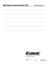
OVERVIEW
What is an SMX-6?
The SMX-6 is a single rack space six by
two automatic mixer designed to be
configured with a computer and appro-
priate software. Once initially setup the
computer becomes optional. The key to
the ability of the SMX-6 operating as a
stand alone automatic mixer is distrib-
uted intelligence
™
. In an IQ System the
brains of the system live out in the sys-
tem. This means the audio system is not
going to be lost even if the computer or
communication cables fail. Due to the
modular nature of the SMX-6, multiple
units also may be used together to form
a wider or deeper automated mixer.
HARDWARE BLOCK DIAGRAM
Refer to the pictures of the front and rear
panels shown above and the block dia-
gram of the SMX-6 mixer on Page 2.
Audio Main Inputs:
Six balanced inputs
with removable 3 pin
barrier block. The
preamp stage in-
cludes:
• M/L/P switches
set each input to line level (L) with 0
dB gain, mic level (M) with 25 dB
additional gain, or phantom (P)
which is 25 dB additional gain and
+44 VDC phantom power.
• A trim pot at each input allows for
prefade gain adjustment of –12 dB
to +21 dB gain after the M/L/P
switch.
Prefade sensors at the output of each
preamp stage sense input audio level
just before the input signal is delivered
to the processor controlled VCAs. There
are two VCAs under processor control
at the output of each sensor. One VCA
controls the gain from input to output mix
1 and the other VCA controls gain from
the input to output mix 2. The net result
is 12 VCAs total, six per output mix.
Audio Stack Inputs:
Two inputs, one per output mix. Connec-
tions are via unbalanced RCA phono
jacks. These inputs are op-amp isolated.
There is no processor control of audio
coming into these inputs. The purpose
of the stack inputs is to allow construc-
tion of a wide mixer with more than six
inputs by taking the outputs of one mixer
and going into the stack inputs of a sec-
ond mixer. This means that main inputs
do not have to be used to expand the
effective size of the overall mixer.
Audio Main Outputs:
There are two summing
buses. Each summing
bus provides the out-
put mix for the corre-
sponding output chan-
nel. Op-amps buffer
the summing bus to the output connec-
tion and balance the audio output. The
outputs are via 3 pin removable barrier
blocks.
Audio Bus Outputs:
In addition to the two main outputs, there
are also two bus outputs. Bus outputs 1
and 2 provide the same audio output as
main outputs 1 and 2. Op-amps buffer
the summing bus to the output connec-
tion and balance the audio output. What
makes the Bus Outputs different are re-
lays under processor control which may
be used to turn on or off the Bus Output
drive. 3 Pin removable barrier blocks are
used.
Aux Port:
The unit is equipped with a TB-3M type
mini-XLR port. This port may be used to
provide a control signal or sense a con-
trol signal.
• Pin 1 is ground reference
• Pin 2 is output under processor
control. When on it provides 10 VDC
at 16 ma. When off it is open collec-
tor (high impedance).
• Pin 3 is sensing input. +5 to +30
VDC is sensed as a logic high. The
circuit floats, therefor tie to ground
or TTL source for definite high or low.
Indicators:
A Power light on the front panel indicates
the unit is plugged into AC mains and
AC power is available. A DSPI data sig-
nal presence indicator lights to indicate
communication or may be forced on via
processor control.
Crown Bus Port:
The Crown Bus is a serial data loop
where components are connected into
the loop and one component serves as
system interface for all. This unit may
serve as a system interface or may sim-
ply operate as a component on a Crown
Bus data loop. Although the Crown Bus
may function on a variety of media,
Crown uses a two-wire 20 ma current
loop for input and output Crown Bus
connections. On this unit connections
are made via 4 pin removable barrier
block. Even if the unit is communicating
directly with a PC via its serial port, it
always functions in software as an ad-
dressable component on a Crown Bus
loop. The unit must have a valid loop
address. A valid address is:
• 1 to 250 set via 8 segment DIP
switch
• No other SMX on the same Crown
Bus data loop may have the same
address.
SMX-6 SENSING MIXER
(Front Panel shown above, Rear Panel shown below)
Page 1 of 5
+–
AUDIO
IN
1
LMP
0
-5
-10
-12
5
10
15
21
ADD 25
FOR MIC
+–+–
AUDIO
OUT
1
MAIN BUS
STACK
IN

@crown
®
* System
®
Product Reference
INPUT 1
PRE-AMP
BALANCED
BUCHANAN
CONNECTOR
GAIN POT
(-12 to +21dB)
M/L/P SWITCH
P = +25dB/+44VDC
M = +25dB
L = 0 dB
VCA
1-1
VCA
1-2
RS232/RS422 or
Crown Local Net
DB25
POWER
SUPPLY
MEMORY
BATTERY
BACKUP
CROWN BUS
AUX PORT
3-PIN
MINI XLR
ENABLE
DSPI
12345678
123456
BAUD RATE
& PARITY
IQ ADDRESS
4-PIN
BUCHANAN
ACTIVE
BALANCE
OUTPUT
AMP
ACTIVE
BALANCE
OUTPUT
AMP
ACTIVE
BALANCE
OUTPUT
AMP
ACTIVE
BALANCE
OUTPUT
AMP
SUMMING
MIX BUS 1
SUMMING
MIX BUS 2
INPUT
SENSOR
TO
CPU
STACK INPUT 1
STACK INPUT 2
TO
CPU
OUTPUT
SENSOR
TO
CPU
OUTPUT
SENSOR
FROM
CPU
FROM
CPU
BUS 1
RELAY
BUS 1
RELAY
FROM
CPU
FROM
CPU
MAIN 1
OUTPUT
BALANCED
BUCHANAN
CONNECTOR
BUS 1
OUTPUT
BALANCED
BUCHANAN
CONNECTOR
MAIN 2
OUTPUT
BALANCED
BUCHANAN
CONNECTOR
BUS 2
OUTPUT
BALANCED
BUCHANAN
CONNECTOR
CPU
(MICRO-
PROCESSOR)
FROM
INPUT
SENSORS
FROM
OUTPUT
SENSORS
TO
VCAs
TO BUS
RELAYS
COMMUNICATION
STANDARD
INPUT 2
PRE-AMP
BALANCED
BUCHANAN
CONNECTOR
GAIN POT
(-12 to +21dB)
M/L/P SWITCH
P = +25dB/+44VDC
M = +25dB
L = 0 dB
VCA
2-1
VCA
2-2
INPUT
SENSOR
TO
CPU
FROM
CPU
FROM
CPU
INPUT 3
PRE-AMP
BALANCED
BUCHANAN
CONNECTOR
GAIN POT
(-12 to +21dB)
M/L/P SWITCH
P = +25dB/+44VDC
M = +25dB
L = 0 dB
VCA
3-1
VCA
3-2
INPUT
SENSOR
TO
CPU
FROM
CPU
FROM
CPU
INPUT 4
PRE-AMP
BALANCED
BUCHANAN
CONNECTOR
GAIN POT
(-12 to +21dB)
M/L/P SWITCH
P = +25dB/+44VDC
M = +25dB
L = 0 dB
VCA
4-1
VCA
4-2
INPUT
SENSOR
TO
CPU
FROM
CPU
FROM
CPU
INPUT 5
PRE-AMP
BALANCED
BUCHANAN
CONNECTOR
GAIN POT
(-12 to +21dB)
M/L/P SWITCH
P = +25dB/+44VDC
M = +25dB
L = 0 dB
VCA
5-1
VCA
5-2
INPUT
SENSOR
TO
CPU
FROM
CPU
FROM
CPU
INPUT 6
PRE-AMP
BALANCED
BUCHANAN
CONNECTOR
GAIN POT
(-12 to +21dB)
M/L/P SWITCH
P = +25dB/+44VDC
M = +25dB
L = 0 dB
VCA
6-1
VCA
6-2
INPUT
SENSOR
TO
CPU
FROM
CPU
FROM
CPU
SMX-6 Basic Block Diagram
(Page 2 of 5)

@crown
®
* System
®
Product Reference
SMX-6 Automatic Mixer (Page 3 of 5)
The Crown Bus is asynchronous with 8
data bits, 1 start bit, 1 stop bit, no par-
ity, and operates at 38400 baud. The
SMX is not a U-Code protocol compo-
nent.
Serial Port:
The serial port on this unit is a female
25 pin D-Shell. RS232 and RS422 are
supported with 8 Data bits, 1 start bit, 1
stop bit, no parity. Up to 19200 baud
supported. The serial port for the SMX
may be used for direct communication
with a PC such that the SMX serves as
interface:
• May serve as interface for up to
20 components connected to the
Crown Bus.
• Components supported include
other SMX units, AMB-5 mixers,
MPX-6 mixers, PIP-AP, PIP-APM,
PIP-APS, all MRX matrixers, and the
White 4700 Series EQ.
• No support for U-Code protocol.
An alternative use for the serial port on
an SMX is the Crown Local Net (CLN).
CLN is a special operational mode that
would be used to build a wide automatic
mixer (two or more SMX units intercon-
nected) where system wide gate count
or priority structure control is required.
CLN involves a pseudo RS422 wiring
interconnection between SMX units.
When an SMX is placed in CLN mode
from within software the serial port may
then be used for CLN and only CLN (in-
terface capabilities are removed. To
configure SMX units for CLN a different
type of component must serve as sys-
tem interface.
Setup Switches:
• The IQ Address is set by an 8 seg-
ment DIP switch. Valid address values
are 1 to 250 (0 and 251-255 are reserved
for system usage).
• RS232/422 Standard switch must be
configured appropriately for use of the
serial port.
• Baud is adjustable via DIP switch up
to 19200. This setting must be config-
ured properly for use of the serial port.
• Parity is set ON or OFF and ODD or
EVEN via DIP switch. Normally set to
OFF, this setting only applies to use of
the serial port.
Memory Backup:
The unit is equipped with a recharge-
able battery. The unit has 60 day
memory backup on full charge.
COMPUTERIZED FEATURES
Monitoring:
Input audio level monitoring has a range
of –40 to +25 dB. Input level is sensed
between the preamp and VCAs for a
total of 6 sensors, one per input. The
output audio level is sensed at each
output mix bus with a range of –40 to
+25 dB.
DSPI:
The Data Signal Presence Indicator
(DSPI) light on the front panel flashes to
indicate data traffic addressed to or from
the unit. This light may be forced on from
software.
Aux Port:
The aux port on the mixer is used to send
or receive a control voltage. From soft-
ware you may turn the aux output on or
off. IQ software is also able to sense the
status of the aux input and is capable of
taking independent action based on a
sensed input.
Bus Output Relays:
Audio bus outputs are identical to their
respective main outputs in every way
except for the addition of software con-
trolled isolation relays.
VCA Gain Control:
The heart of the SMX is its functionality
as a mixer. Each input may be routed to
either or both outputs by VCAs under
processor control. The processor may,
in turn, be set up to control VCAs using
on board automatic intelligence or may
be controlled in real time manually from
software. The VCAs offer a control range
of –100 to +25 dB.
MANUAL MIXING IN REAL TIME
All setup for manual or automatic op-
eration is accomplished, at least initially,
with IQ software from a PC. The SMX
has a software switch that puts the unit
into a manual mode or an automatic
mode. When in manual mode you may
make changes from software that affect
VCA gain in real time. Gain may also be
manipulated in real time from alternate
control devices such as a Drone or a
third party control device (Ex. AMX,
Crestron, Interface Controls, etc.). Once
VCA gains are set from the PC (or con-
trol device) the processor maintains that
gain structure until it receives an instruc-
tion to change. In the manual mode the
automatic features such as compres-
Gate
Priority
Input
Comp.
Auto
Level
Gate Count
Output Compressor
Manual Mode
"Real Time" Settings
Automatic Mode Settings
ON
OFF
ASA SWITCH
VCA Control
SMX-6 Manual or Automatic Operation

@crown
®
* System
®
Product Reference
SMX-6 Automatic Mixer (Page 4 of 5)
sors are disabled. Functions other than
VCA gain control (Bus relays, DSPI, and
aux output controls) are only controlled
manually.
AUTOMATIC MIXING
Feature Set:
To make use of the automatic mixing
power of the SMX-6 the unit must be
configured with IQ software. Once the
unit is placed in automatic mode and its
intelligence is fully configured, the unit
will mix without further outside commu-
nication being necessary. Intelligence is
programmable independently for each
VCA. Features making up the total mix-
ing algorithm are comprised of user de-
fined variables set in software. These
features, also called algos, include:
• Max Gain
• Input Noise Gate
• Duck Priority
• Input Compressor
• Auto Level
• Output Compressor
• Gate Count
• Max Number of Open Mics
• Crown Local Net
Max Gain
The purpose of Max is to prevent feed-
back and provide a safety limit. Max
Gain is defined as the maximum gain of
the VCA regardless of interaction with
other algos any time an input is gated
on, or if the gate function is not used.
Max Gain may be set –100 to +25 dB
Gain for each VCA. Two global settings
are used to tie Max Gain to the manual
gain controls. These are Max Gain
Tracks Control Block and Control Block
Override. These are two switches which
are used, usually together, to allow for
smooth operational control of Max Gain
for semi-automatic operation. The need
for this mode of operation may arise
when using third party control system
products or some types of IQ controls.
Input Noise Gate
The purpose of a noise gate is to attenu-
ate an input when little or no input sig-
nal is present. With the SMX-6 you con-
figure various parameters which define
the precise operation of the gating fea-
ture at each input. Several other auto-
matic features also depend on proper
operation of the gating function. Param-
eters involved are:
• Gate is an ON/OFF switch to en-
able or disable this feature for each
VCA.
• Threshold is a parameter that sets
the input level required to gate on
for each VCA. The range is –100 to
+25 dB sensed.
• Low Set is a parameter that sets
the gain of the VCA when the input
is gated off. The range is –100 to
+25 dB gain.
• Delay Time is the time delay in
seconds after the input level drops
below
Threshold
until the VCA ac-
tually gates off. The range is 0.2 to
30 seconds.
Duck Priority
The duck priority feature allows the mixer
to have a priority structure of up to six
levels. Each output channel may have
a different priority structure. Parameters
involved are:
• Duck priority is an ON/OFF switch
tells each VCA whether or not they
participate in the priority structure.
• Priority level is a setting from 1 to
6 where 1 = highest and 6 = lowest
priority. Each VCA is set indepen-
dently.
Input Compressor
The SMX-6 mixer is equipped with both
input compressor and an output com-
pressor features. The input compressor
differs from a conventional compressor
due to its feed forward structure. This
feed forward technology prevents
“breathing” and virtually eliminates
“pumping.” The parameters for the in-
put compressor are:
• Compressor is the ON/OFF switch
for each VCA.
• Threshold is the sensed input level
above which the compressor be-
gins to actuate. The range is –100
to +25 dB and is set at each VCA.
• Ratio may be set to 1:1, 2:1, 4:1,
8:1, 16:1, 32:1 or ∞:1 for each VCA.
• Release Time is the time in sec-
onds to release compression at a
slope of seconds per 10 dB. The
range is 0.2 to 30 seconds for each
VCA.
• Attack Time is a global setting for
all VCAs and may be set to fast or
slow depending on your preference.
Auto Level
The auto level feature of this unit is de-
signed to handle long term input level
variations to maintain a consistent out-
put level. This is basically done by se-
lecting a desired average output level
then setting up the other parameters to
define the response. Parameters in-
clude:
• Auto Level is an ON/OFF switch
that enables or disables the auto
level function for each VCA.
• DAOL (Desired Average Output
Level) is the target output level you
set. Once the auto level function is
working the VCA raises or lowers
gain as necessary to achieve the
DAOL given the sensed input level.
The DAOL setting range is –100 to
+25 dB.
• Reaction Time is the time in sec-
onds to change gain 10 dB toward
the necessary gain structure to ob-
tain the DAOL. The range is 0.2 to
30 seconds.
• Idle Gain is the gain that the VCA
goes to when the input initially gates
on. In other words it is the starting
point. Used in conjunction with other
features this parameter can afford
the mixer a variety of complex ef-
fects such as ramping in of back-
ground music.
• Auto Level Gate Function is a glo-
bal setting that may be set to Open
To Idle Gain or Open To Last Posi-
tion. When set to Open To Idle Gain
an input will initially gate on to the
Idle Gain setting and the auto level
feature will take over from there. The
advantage to this setting is that it
allows for ramping and input gain
is the same every time a gate first
comes on. When set to Open To Last
Position the auto level feature re-
members the gain of the VCA at the
time the input last gated off so that
gain goes back to that level the next
time that the gate opens again.
Output Compressor
The SMX output compressor is different
that a conventional output compressor
because you can actually choose which
inputs participate in output compres-
sion. This can be a valuable tool if you
have microphones on some inputs and
a playback source on other inputs. You
might reasonably expect that the play-
back source such as a CD or tape player

@crown
®
* System
®
Product Reference
will not output level which would require
compression, so you might not config-
ure those inputs to participate in the
output compression scheme. Output
compressor parameters are primarily
per output rather than input and include:
• Compressor is a master ON/OFF
switch for each output that enables
or disables output compression for
that output.
• Limiter is an ON/OFF switch for
each VCA that configures which in-
puts may participate in output com-
pression.
• Threshold is the sensed output
level above which the compressor
begins to actuate. The range is –
100 to +25 dB and is set per out-
put.
• Ratio may be set to 1:1, 2:1, 4:1,
8:1, 16:1, 32:1 or ∞:1 for each out-
put.
• Release Time is the time in sec-
onds to release compression at a
slope of seconds per 10 dB. The
range is 0.2 to 30 seconds for each
output.
Gate Count
The gate count feature attenuates all
gated on inputs when more than one
input is gated on by a predetermined
amount. The purpose of this feature is
to prevent feedback problems due to
multiple open mics. Settings are per
output channel. Parameters include:
• Gate Count Master is a global ON/
OFF switch.
• Gate Count is a set of ON/OFF
switches that dictates which VCAs
participate in the gate count.
• Amount is how much attenuation
per additional open mic. Each out-
put is set within a range of 0.5 to 16
dB.
Max Number of Open Mics
This feature is sometimes called a fili-
buster control because it can make the
mixer work in a first come first served
manner by limiting how many inputs may
gate open simultaneously. The only pa-
rameter to set is the actual maximum
number of open mics. The range is 1 to
6 with settings for each output.
Crown Local Net
Crown Local Net (CLN) is a special
mode of operation that is used when two
or more SMX units are stacked together
to form a wide automatic mic mixer
where system wide duck priority or gate
count features are required. This in-
volves both software and hardware
setup and it also requires that the serial
port of each mixer be dedicated to CLN
use. Note that if an SMX mixer is going
to be used on a CLN that the SMX can
not be used as a system interface. Due
to the number of steps and detail in-
volved with setup of a CLN, please con-
tact the Crown Technical Support Group
if you are interested in more information
on this feature.
SYSTEM LEVEL INFORMATION
Communication:
In an IQ System the basic communica-
tion structure is based on the premise
that it must be able to support a PC be-
ing used with several IQ components.
The computer is connected to the IQ
System interface via RS232. The inter-
face converts the protocol from RS232
to Crown Bus media and back again. In
a small system or a single SMX system
the SMX itself may serve as the system
interface. The IQ-INT II, IQ-PSI, Drone,
SMX-6, AMB-5 and MPX-6 are all com-
ponents which may serve as a system
interface for an SMX-6. The Crown Bus
is a serial data loop carrier of IQ com-
mand protocol. Crown has implemented
it as a two wire twisted pair current loop
to allow for low cost long distance con-
nections. For very long loops (over 1000
feet) data repeaters (IQ-RPT) or fiber
optic cable may be used to connect
equipment rooms that are some dis-
tance apart. The Crown Bus itself does
not carry audio.
U-Code Protocol:
U-Code is new form of IQ command
protocol developed for enhanced new
product and third party product devel-
opment. At this time the SMX-6 firmware
is not written in U-Code. Although it may
be used in systems with U-Code prod-
ucts, the SMX-6 may not be used as
system interface for U-Code products.
Software:
Several IQ Software packages are avail-
able to communicate with an SMX-6.
Each unit is shipped with basic DOS
software which allows you to communi-
cate with the SMX-6, AMB-5, MPX-6,
and MRX Matrixer units. More advanced
software includes the Turbo or Sys-
Config software packages. Turbo is a
DOS program that includes powerful
graphics support and support of the full
IQ product line. Sys-Config is an ad-
vanced package which has security,
scheduling, alert reporting, and other
powerful features plus the power of
Turbo built in.
PC Requirements:
The computer you select for use with
your IQ System is very important. Exact
minimum requirement vary depending
on the software package being used,
but for the more advanced software your
machine should at least be a 486SX/33
with the following: 4 MB RAM, 16550
UART for the com port used by IQ, DOS
6.2, Mouse (with DOS driver, third but-
ton features supported). In most cases
Turbo software will operate as a DOS
application from Windows,
®
including
Windows 95.
®
SPECIFICATIONS
Maximum Input Level (Mic): +7 dBu.
Maximum Input Level (Line): +32 dBu.
Phantom Power: +44 VDC.
AC Power: 120/240 VAC 50/60 Hz.
Common Mode Rejection: 55 dB: 60 to 1 kHz
typical; 45 dB: 20 to 20 kHz.
Frequency Response: +0/-1 dB, 20 to 20 kHz.
THD: <0.05% at +4 dBm output; <0.15% at
+20 dBm output 20 to 20 kHz measured at
mic input with 40 dB gain.
Noise: Output noise all inputs off is –80dBu
(106 dB below rated output); output noise
with one line input at 0 dB is 80 dB; equiva-
lent input noise at mic input with 46 dB of
gain and 150 ohm source is –125 dBu. Note
that noise specs are typical, unweighted,
and 20 to 20 kHz.
Crosstalk: Adjacent inputs/outputs at 1 kHz
better than –80 dB; adjacent inputs/outputs
20 to 20 kHz better than –65 dB.
Guaranteed Excellence
@crown
Crown International, Inc.
Professional Audio Division
PO Box 1000
Elkhart, IN 46515-1000
Ph. 800-342-6939/219-294-8200
Fax. 219-294-8301
Trademark Notice:
Algo,
™
Distributed Intelligence,
™
and
SMX-6
™
are
trademarks,
Crown
®
and
IQ System
®
are regis-
tered trademarks of Crown International Inc.
SMX-6 Automatic Mixer (Page 5 of 5)
/