Page is loading ...

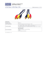
P 3 Preamplifier
Owner’s Guide

THANK YOU!
Congratulations and Thank You for Choosing Parasound
Your new Parasound P 3 Preamplifier presents the latest advancements in audio technology.
The P 3 is built to the strict quality and performance standards set by Parasound. We’re
proud to offer you this exceptional audio component that will bring many years of
enjoyment and dependability.
Here at Parasound, we design our products to perform to a higher level of flexibility
and sonic performance than you may have expected. We encourage you to read this
entire manual to learn all the features and capabilities of your new Halo P 3 Preamplifier.
If you’re eager to get up and running right away, simply follow the basic step-by-step
instructions to connect and operate the P 3. If you want to learn about some of the
technical and design aspects of your P 3, refer to the Technically Speaking and Design
Overview sections in the back of the manual. If you run into difficulties, the Troubleshooting
Guide should help you quickly remedy the problem.
We appreciate you taking the time to read these instructions and thank you for selecting
Parasound for your listening pleasure.
The Parasound Staff
Keeping Records for Future Reference
Record the serial number located on the bottom of your P 3 below. You should also note
your Parasound Dealer’s name and phone number. We recommend that you keep your
purchase receipt with this manual and store them both in a safe place. You may need to
refer to this information sometime in the future.
Parasound P 3 Preamplifier Serial #: __________________
Parasound Dealer: ____________________________________
Phone Number:_______________________________________
Date of Purchase: _____________________________________
YOU SHOULD KNOW
There is no Parasound warranty for this unit if it was not purchased from an Authorized
Parasound Dealer. Investigate any warranty claims made by unauthorized dealers very
carefully as you will need to depend entirely upon the dealer, and NOT upon Parasound.
Unauthorized dealers may lack the capability to arrange repairs of Parasound equipment.
Authorized Parasound Dealers are listed at www.parasound.com or you can call 415-397-7100
between 8:30 AM and 4:30 PM Pacific time.
A missing or tampered serial number could indicate that this unit was stolen or sold by an
unauthorized dealer. You should return it to your dealer immediately for replacement or a
full refund.

UNPACKING AND PLACEMENT GUIDELINES FOR THE P 3
__________________________________________________________________________________________
CONNECTING A SOURCE COMPONENT TO THE BALANCED DIRECT 1 INPUTS ON THE P 3
__________________________________________________________________________________________
CONNECTING A SOURCE COMPONENT TO THE UNBALANCED DIRECT 1 INPUTS ON THE P 3
__________________________________________________________________________________________
CONNECTING A SOURCE COMPONENT TO THE P 3 UNBALANCED DIRECT 2 INPUTS
__________________________________________________________________________________________
CONNECTING A TURNTABLE OR OTHER COMPONENT TO THE AUX INPUTS ON THE P 3
__________________________________________________________________________________________
CONNECTING OTHER SOURCE COMPONENTS TO THE CD AND TUNER INPUTS ON THE P 3
__________________________________________________________________________________________
CONNECTING AN ANALOG TAPE DECK TO THE P 3
__________________________________________________________________________________________
CONNECTING AN EXTERNAL SIGNAL PROCESSING COMPONENT TO THE P 3
EXTERNAL LOOP JACKS
__________________________________________________________________________________________
CONNECTING THE P3 TO THE BALANCED INPUTS ON YOUR POWER AMPLIFIER
__________________________________________________________________________________________
CONNECTING THE P 3 TO THE UNBALANCED INPUTS ON YOUR POWER AMPLIFIER
__________________________________________________________________________________________
CONNECTING AN INFRARED REPEATER SYSTEM TO THE P 3
__________________________________________________________________________________________
TURNING ON THE P 3 WITH AN EXTERNAL TRIGGER VOLTAGE
__________________________________________________________________________________________
TRIGGERING ON ANOTHER COMPONENT FROM THE P 3’S TRIGGER OUTPUT JACK
__________________________________________________________________________________________
RS232 CONTROL
__________________________________________________________________________________________
CONNECTING THE P 3 AC POWER CORD
__________________________________________________________________________________________
OPERATING YOUR P 3
__________________________________________________________________________________________
FRONT PANEL AND REMOTE CONTROL
__________________________________________________________________________________________
TROUBLESHOOTING GUIDE
__________________________________________________________________________________________
SERVICING YOUR P 3
__________________________________________________________________________________________
TECHNICALLY SPEAKING
__________________________________________________________________________________________
PARASOUND P 3 DESIGN OVERVIEW
__________________________________________________________________________________________
PARASOUND P 3 SPECIFICATIONS
__________________________________________________________________________________________
TABLE OF CONTENTS
P 3 Preamplifier
19
20
21
22
24
25
16
13
12
15
14
11
10
9
8
7
5
4
2
1
3
6

UNPACKING AND PLACEMENT GUIDELINES FOR THE P 3
Unpacking Your P 3
Carefully unpack your P 3 from the shipping carton and remove all the enclosed accessories:
• Remote control with two AAA batteries
• Detachable AC cord
• Two Trigger control wires with a 2.5 mm sub-mini plug on each end.
While you are unpacking your new preamplifier, inspect it thoroughly for possible shipping
damage. If you see any, contact your Parasound dealer right away. Be sure to save and store
both the inner and outer cartons and packing inserts for possible future transport. To save room
for storage, you can cut the seams on the bottom of the cartons and flatten them.
Placement Guidelines for Your P 3
For trouble-free operation and long-term reliability, follow the simple guidelines below to help
decide where to locate your P 3 in your system.
• Place the P 3 on a separate shelf that will adequately support its weight.
• Keep it away from heat sources such as air ducts or radiators.
• Leave at least 1” of space on all sides and the top. This helps facilitate passive
heat dissipation.
Rack Mounting Your Parasound P 3
If you plan to mount the P 3 into a standard 19” wide equipment rack, you will need to purchase
the optional Parasound HRA 2 Rack Mount Adapter. With its four feet removed, the P 3 chassis
and front panel height occupies two rack spaces (3-1/2” or 88mm). When mounting equipment
below the P 3, you will also need to allow about 1/8” below the unit for the bottom chassis
screws. A standard single rack space is 1-3/4” high in a 19” wide equipment rack. This
measurement standard was developed by the EIA (Electronic Industries Association) so
manufacturers of electronic components and equipment racks could build products in
standardized heights that would fit in a uniform space. Please call your Parasound dealer or call
directly to Parasound Technical Services if you need additional advice about rack mounting the P 3.
1

YOU SHOULD KNOW
Balanced XLR Jacks and Their Pin Configuration
The balanced inputs of the P 3 use XLR jacks that conform to the industry standard of: Pin 1:
Ground, Pin 2: Positive (+), Pin 3: Negative (--). The balanced outputs on some components
use terminals with 3 screws instead of XLR jacks. These are compatible with the P 3 as long
as you match the bare wires to the corresponding pins on the XLR plug: + to pin 2, - to pin 3,
and Ground to pin 1.
Interconnect Cables and Their Color Codes
Common color codes for input and output jacks are red for right and white for left. Match the
colors at the outputs from your preamplifier or surround controller to the inputs on your P 3
so you’ll always hear the channels in their intended position.
Left and Right Direct 1 Input Jacks
Balanced connections will give you the best sound. If your source components have balanced
XLR output jacks, we recommend that you connect them to these inputs. Refer to the Balanced
and Unbalanced Lines in the Technically Speaking section for additional information about
why we recommend using balanced lines.
What You’ll Need:
• One pair of balanced interconnect cables with XLR connectors
• An audio source component with balanced output connectors
Before Connecting
Leave the P 3’s AC cord disconnected until you have made all connections to prevent
any surprise burst of sound.
Make sure that all your cables are long enough so they are not strained or stretched
once they are connected.
Make sure the Direct 1 Select switch on the P 3 is in its balanced (left) position.
To Connect
Plug the male end of one of the balanced cables into the right Balanced Direct 1 input
jack on the P 3
Plug the female end of this cable into the right channel output connector on your
source component.
Repeat steps 1 and 2 for the left channel.
CONNECTING A SOURCE COMPONENT TO THE BALANCED
DIRECT 1 INPUTS ON THE P 3
1
2
3&4
2
XLR Connectors
Male
Female

Left and Right Direct 1 Unbalanced Inputs
If your best-sounding audio source component has only unbalanced RCA output jacks,
connect them to the P 3 unbalanced Direct 1 input jacks.
What You’ll Need:
• One pair of shielded interconnect cables with RCA plugs
• A source component with RCA output jacks
Before Connecting
Leave the P 3’s AC cord disconnected until you have made all connections to prevent
any surprise burst of sound.
Make sure that all your cables are long enough so they are not strained or stretched
once they are connected.
Make sure the Direct 1 Select switch on the P 3 is in its unbalanced (right) position.
To Connect
Plug one end of the first cable into the right Direct 1 input jack on the P 3.
Plug the other end of this cable into the right channel output jack on the source component.
Repeat steps 1 and 2 for the left channel.
CONNECTING A SOURCE COMPONENT TO THE UNBALANCED
DIRECT 1 INPUTS ON THE P 3
3
1
2
RCA Plugs
Right
Left
3&4
CAUTION
1
3
2
4
Right
Left
COMPONENTS
AM
FM
87
510
TAPE DECK
OUTPUTS
?
CD PLAYER
TUNER
AUX
YOU SHOULD KNOW
To achieve the purest sound reproduction, the tone control and record outputs don’t function
for Direct Inputs 1 and 2. Therefore, you cannot alter the tone or make recordings from
components that are connected to the Direct inputs.

Direct 2 Unbalanced Input Jacks
The P 3 Unbalanced Direct 2 input jacks are for your next-best-sounding source component if
the Direct 1 input jacks are already connected to another source.
What You’ll Need:
• One pair of shielded interconnect cables with RCA plugs
•A source component with RCA output jacks
Before Connecting
Leave the AC cord of the P 3 disconnected until you have made all connections to
prevent any surprise burst of sound.
Make sure that all your cables are long enough so they are not strained or stretched
once they are connected.
To Connect
Plug one end of the first cable into the right Direct 2 input jack on the P 3.
Plug the other end of this cable into the right channel output jack on the source component.
Repeat steps 1 and 2 for the left channel.
CONNECTING A SOURCE COMPONENT TO THE P 3
UNBALANCED DIRECT 2 INPUTS
4
1
2
RCA Plugs
Right
Left
3&4
CAUTION
1
3
2
4
Right
Left
COMPONENTS
AM
FM
87
510
TAPE DECK
OUTPUTS
?
CD PLAYER
TUNER
AUX

Connecting a Source Component to the Aux Inputs on the P 3
The P 3 has a single Aux input, but two pairs of Aux jacks for either a phono or a line level
source. The Aux Select switch determines if you’ll hear the source connected to the Aux-Phono
jacks or the source connected to the Aux-Line jacks.
It’s possible to use both pairs of Aux jacks, but this requires using the rear panel Aux Select
switch when you want to switch from a phono to a line level source.
What You’ll Need:
• A turntable or other source component
• One pair of shielded interconnect cables with RCA plugs. Most turntables
have these cables permanently attached
Before Connecting
Remove power to all the components in your audio system.
Move the Aux Select switch so it points left toward the Aux-Phono jacks.
To Connect
Insert one of the turntable cable plugs into the P 3 right Aux-Phono jack.
Insert the other plug into the P 3 left Aux-Phono jack.
Connect the ground wire from your turntable to the P 3 Phono-GND (Ground) terminal.
Unscrew the GND terminal post slightly and insert the bare end or spade lug of the
turntable’s ground wire. Tighten the terminal post down firmly.
Connecting Another Source Component to the Aux Inputs on the P 3
Follow the same steps as when connecting a turntable with the following exceptions:
Move the Aux Select switch so it points right toward the Aux-Line jacks.
There is no separate ground wire for line-level source components.
To Connect
Plug one end of the first cable into the right Aux-Line input jack on the P 3.
Plug the other end of this cable into the right channel output jack on the source component.
Repeat steps 1 and 2 for the left channel.
CONNECTING A TURNTABLE OR OTHER COMPONENT TO
THE AUX INPUTS ON THE P 3
5
1
2
3&4
1
2
3&4
CAUTION
1
2
Right
Left
OUTPUTS
TURNTABLE
4
3

Connect the outputs of your CD player, tuner, or any other line level source to the CD and
Tuner jacks. All of the line level inputs are electrically identical.
What You’ll Need For Each Input Connection:
• One pair of shielded interconnect cables with RCA plugs
•A source component with RCA output jacks
Before Connecting
Remove power to all the components in your audio system.
To Connect
Plug one end of the first cable into the right CD (or Tuner) jack on the P 3.
Plug the other end of this cable into the right channel output jack of the source component.
Repeat steps 1 and 2 for the left channel.
CONNECTING OTHER SOURCE COMPONENTS TO THE CD
AND TUNER INPUTS ON THE P 3
6
1
2
RCA Plugs
Right
Left
3
&4
CAUTION
2
4
Right
Left
COMPONENTS
AM
FM
87
510
OUTPUTS
CD PLAYER
TUNER
1
3

Connect the input and output from your analog tape recorder to the Tape Play and Rec (Record)
jacks of the P 3. See Tape Record and Play Circuitry in the Technically Speaking section for
more information.
What You’ll Need:
• Two pairs of shielded interconnect cables with RCA plugs
• An analog recording component such as a cassette deck or a
MiniDisc recorder
Before Connecting
Remove power to all the components in your audio system.
To Connect
Plug one end of a cable into the right Tape Play/In jack on the P 3.
Plug the other end of this cable into the right line out (or Output) on the tape deck.
Repeat for the left channel.
Plug one end of another cable into the left Rec/Out jack on the P 3.
Plug the other end of this cable into the left Tape Rec/In (or Record) jack on the tape deck.
Repeat for the right channel.
RCA Plugs
Right
Left
CONNECTING AN ANALOG TAPE DECK TO THE P 3
7
1
2
3&4
5
6
7&8
CAUTION
1
3
4
2
Right
Left
COMPONENTS
TAPE DECK
OUTPUTS
Right
Left
INPUTS
7
8 6
5

CONNECTING AN EXTERNAL SIGNAL PROCESSING
COMPONENT TO THE P 3 EXTERNAL LOOP JACKS
You can connect signal-processing equipment such as a frequency-shaping equalizer into the signal
path of the P 3 via its External Loop Connections. See External Loop In/Out Connections in the
Technically Speaking section for more information.
What You’ll Need:
• Two pairs of shielded interconnect cables with RCA plugs
•A signal-processing component
Before Connecting
Remove power to all the components in your audio system.
Remove the two U-shaped metal jumpers that are already inserted into the External
Loop Out and External Loop In jacks. Make sure to save these jumpers and put them
where you can locate them if you need them in the future.
To Connect
Plug a cable into the Left Loop/Out jack on the P 3.
Plug the other end of this cable into the left input jack on the signal-processing component.
Repeat for the right channel.
Plug a third cable into the Left Loop/In jack on the P 3.
Plug the other end of this cable into the left output jack on the signal-processing component.
Repeat for the right channel.
8
1
2
5
6
YOU SHOULD KNOW
Your system cannot function if the U-shaped jumpers are removed and a component is not
connected to the P3 Loop/Out and Loop/In jacks. If you misplace the jumpers, you can substitute
a pair of shielded cables to reconnect the P3 Loop/Out and Loop/In jacks for each channel.
RCA Plugs
Right
Left
3&4
7&8
CAUTION
3
1
2
4
Right
Left
COMPONENTS
SIGNAL PROCESSOR
INPUTS
Right
Left
OUTPUTS
7
8 6
5

For best sound performance, use the P 3 Balanced Line Output connections if your power
amplifier is equipped with balanced inputs.
What You’ll Need:
• One pair of balanced interconnect cables with XLR plugs
• An amplifier with balanced XLR input jacks
Before Connecting
Leave the AC cord disconnected until you have made all connections to prevent any
surprise burst of sound.
Make sure that all your cables are long enough so they are not strained or stretched
once they are connected.
To Connect
Plug the female end of one of the balanced interconnect cables into the P 3’s right
channel Balanced Line Output 2 jack.
Plug the male end of this cable into the balanced right channel input jack on your
power amplifier.
Repeat steps 1 and 2 for the left channel.
CONNECTING THE P 3 TO THE BALANCED INPUTS ON
YOUR POWER AMPLIFIER
9
1
2
YOU SHOULD KNOW
Balanced XLR Jacks and Their Pin Configuration
The balanced outputs of the P 3 use XLR jacks that conform to the industry standard of: Pin 1:
Ground, Pin 2: Positive (+), Pin 3: Negative (--). The balanced inputs on some components use
terminals with 3 screws instead of XLR jacks. These are compatible with the P 3 as long as
you match the bare wires to the corresponding pins on the XLR plug: + to pin 2, - to pin 3, and
Ground to pin 1.
Interconnect Cables and Their Color Codes
Common color codes for input and output jacks are red for right and white for left. Match the
colors at the outputs from your preamplifier or surround controller to the inputs on your P 3
so you’ll always hear the channels in their intended position.
XLR Connectors
Male
Female
3&4
CAUTION
Right
Left
INPUTS
1
3
2
4
POWER AMPLIFIER

CONNECTING THE P 3 TO THE UNBALANCED INPUTS ON
YOUR POWER AMPLIFIER
Use these outputs if your power amplifier does not have balanced input connectors or if you
prefer to use unbalanced connections.
What You’ll Need:
• One pair of shielded interconnect cables with RCA jacks
•A power amplifier with unbalanced input jacks
Before Connecting
Remove power to all the components in your audio system.
To Connect
Plug one end of the first cable into the right channel Line Output 1 jack on the P 3.
Plug the other end of this cable to the right channel input jack on your power amplifier.
Repeat steps 1 and 2 for the left channel.
10
CAUTION
Right
Left
INPUTS
3
1
2
4
POWER AMPLIFIER
1
2
3&4
RCA Plugs
Right
Left

CONNECTING AN INFRARED REPEATER SYSTEM TO THE P 3
The External Remote Input jack is for a wired infrared repeater system or system controller. It
eliminates the need for a stick-on front panel IR flasher. There is also a Loop Out jack to loop
or “daisy chain” to an additional infrared remote-controlled component.
What You’ll Need:
• An infrared receiving eye
• A power supply for the IR system
• A connecting block from the external IR system’s manufacturer
• One cable with a 1/8” mini-plug on each end
Before Connecting
Remove power to all the components in your audio system.
To Connect
Plug the receiving eye into the input on the connecting block.
Plug the power supply into the connecting block.
Push one of the 1/8” mini-plugs into the connecting block.
Push the plug at the other end of this cable into the External Remote In jack on the P 3.
Plug an IR flasher or other IR repeater into the P 3’s External Remote Loop Out jack to
control another component if desired.
11
1
2
3
4
5
YOU SHOULD KNOW
Some IR systems may vary slightly from this connection. Refer to the installation manual of
your repeater system for more information.
CAUTION
Input
Output
2
5
1
3
4
IR CONNECTING BLOCK.

TURNING ON THE P 3 WITH AN EXTERNAL TRIGGER VOLTAGE
The P 3 can be turned on automatically when a trigger voltage is received from an external DC
voltage source such as a system controller.
What You’ll Need:
• A trigger cable with 2.5 mm sub-mini plugs (provided)
• A component with an external +9Vdc to +12Vdc trigger
voltage
Before Connecting
Remove power to all the components in your audio system.
To Connect
Plug one end of this cable into the 12V Trigger Input jack of the P 3.
Plug the other end into the component with an external DC trigger voltage.
1
2
2.5 mm sub-mini plug
YOU SHOULD KNOW
If the component you want to use to control your P 3 doesn’t have a 2.5 mm trigger output
jack, you can cut off one plug and terminate the end of the wire. The lead with the red stripe
is positive and the lead without a stripe is negative.
You cannot automatically turn on the P 3 by applying AC power to the unit. Therefore, the P 3
will not turn on automatically if it is connected to a switched AC outlet.
12
CAUTION
Output
2
1
SYSTEM CONTROLLER

The 12V Trigger Output jack generates its own +12 Vdc voltage whenever the P 3 is turned on
so it can trigger other components such as a Parasound power amplifier. This output will
provide up to 200 mA of current to trigger an external component.
What You’ll Need:
• A second trigger cable with 2.5 mm sub-mini plugs (provided)
•A component that can be triggered with an external +9 Vdc to
+12 Vdc trigger voltage
Before Connecting
Remove power to all the components in your audio system.
To Connect
Connect one end of this cable to the 12V Trigger Output jack on the P 3.
Connect the other end to the component that you want to trigger.
TRIGGERING ON ANOTHER COMPONENT FROM THE P 3’S
TRIGGER OUTPUT JACK
13
1
2
2.5 mm sub-mini plug
YOU SHOULD KNOW
If the component you want your P 3 to control doesn't have a 2.5 mm trigger input jack, you.,
you can cut off one plug and terminate the end of the wire. The lead with the red stripe is
positive and the lead without a stripe is negative.
CAUTION
Input
2
1
TRIGGERED COMPONENT

RS232 CONTROL
The P 3 External Control connector is used only if you have a computer-based system controller.
The P 3 is compatible with most system controllers. RS232 codes for Parasound units can be
downloaded from www.parasound.com.
Connecting a Controller to the RS232 Port of the P 3
What You’ll Need:
•A computer-based control system with RS232 serial output
• An RS232 serial cable with a DB9 connector. The pin
configuration is: Pin 2-transmit, Pin 3-receive, Pin 5-ground
Before Connecting
Remove power to all the components in your audio system.
To Connect
Connect the RS232 cable to the output of the computer-based control system.
Plug the RS232 cable into the RS232 Control connector on the P 3.
1
2
RS232 Connector
YOU SHOULD KNOW
If your system controller doesn’t use a DB9 connector, the pin configuration of its connector
must correspond to: Pin 2 transmit, Pin 3 receive, Pin 5 ground.
14
CAUTION
COMPUTER CONTROL
1
2

CONNECTING THE P 3 AC POWER CORD
AC Power Connections
We recommend plugging your P 3 into the same AC outlet or power strip used for your
accompanying audio components, especially the power amplifier and source components.
What You’ll Need:
• An IEC 65 AC Cord (provided)
• An AC outlet or power strip within reach of the AC cord
Before Connecting
Remove power to all the components in your audio system.
To Connect
Plug the female end of the AC cord into the AC receptacle on the rear of the P 3.
Plug the male end of the AC cord into an active AC outlet.
AC Voltage Selection Switch
The P 3 can operate on either 110-120 Vac or 220-240 Vac operation. When you
purchased your P 3, its rear panel Voltage Selector switch was already set for
the proper voltage in your area. Nevertheless, it’s wise to double-check it
before plugging into an AC outlet.
If you move to a location with a different line voltage, you can easily convert the P 3.
For 110-120 Vac Operation: Remove the lock-out bracket with a phillips
screwdriver. Next, slide the switch toward the left until the groove on the
switch lines up with 115/60Hz. Replace lock-out bracket.
For 220-240 Vac Operation: Remove the lock-out bracket with a phillips
screwdriver. Next, slide the switch toward the left until the groove on the
switch lines up with 230V/50Hz. Replace lock-out bracket.
If you’re unsure about the correct setting for your region, please consult your
Parasound dealer or a qualified service technician.
15
1
2
1
2

Turning the P 3 On and Off
You can turn the P 3 on and off with the On-Off button on its front panel, with the On
and Off buttons on its remote control handset, or with an external DC source.
Turning On the P 3
Press either the On-Off Button on the front panel or the On button on the remote control.
Turning Off the P 3
Press either the On-Off Button on the front panel or the Off button on the remote control.
YOU SHOULD KNOW
Even when the P 3 is turned off, there is a faint glow behind its On-Off button and its P logo
badge to indicate that AC power is present. When you turn it on, the P badge and the glow
behind the On-Off button brighten, and the front panel displays the previously selected input
and volume.
Adjusting the Volume Level
You can control the overall volume level of the P 3 in 1 dB steps with the large knob on
the front panel or the Volume and buttons on the remote control.
To increase volume, turn the volume control knob in a clockwise direction or press the
Volume button on the remote control.
To decrease volume, turn the volume control knob in a counter-clockwise direction or
press the Volume button on the remote control.
YOU SHOULD KNOW
P 3 Volume Indication
The P 3 displays volume from 00 to 80. These numbers do not correspond to reference voltages.
Muting the Main Outputs
You can mute the output of the P 3 whenever you want to quickly interrupt listening
and return to the same volume setting. The Mute button reduces volume to zero much
faster than turning the knob on the front panel or holding the Volume button on the
remote control.
Muting the Output of the P 3
Press the Mute button on the remote control. MUTE will flash in the front panel display.
The small red indicator at the lower right of the front panel will illuminate red.
Taking the P 3 Out Of the Mute Mode
Press the Mute button on the remote control. You will also defeat muting by adjusting
the volume control knob or by pressing the Volume or buttons on the remote handset.
YOU SHOULD KNOW
When you press the Mute button on the remote control, the signal is muted at the Line Out,
Phones, and Loop Output jacks, but not at the Tape Rec/Out jacks. You will automatically turn
off mute if you press the Mute button a second time or change the volume level.
OPERATING YOUR P 3
16
See page 19 for P 3 Front Panel and Remote Control layout
V
V
V
V
V
V
V

OPERATING YOUR P 3 continued
Selecting the Input Source
You can select the input source by repeatedly pressing the Source button on the front
panel until the desired source name appears in the status display. You can also select
the desired source directly with the Source select buttons on the remote control.
The Source buttons on the remote control correspond to the following:
Remote Control Button Input
Direct 1
Direct 2
Aux (line or phono selected at rear panel)
Tuner
CD
Tape
Selecting the Input Source on the P 3
Press the front panel Source button until the desired input source is selected. You can
also press the Source buttons on the remote control.
Adjusting the Balance Level
You can adjust the balance of the P 3 with the < Balance > buttons on the front panel.
Each press of a button in either direction increases the relative balance in 2 dB increments
Adjusting Balance toward the Right Channel
Press the Balance > button once to show the present balance level in the display.
The next time you press the Balance > button it will change the balance.
Keep pressing the Balance > button until the desired balance is reached. Each time
you press the Balance > button, the right channel level will increase by 2 dB.
Adjusting Balance toward the Left Channel
Press the < Balance button once to show the present balance level in the display.
The next time you press the < Balance button it will change the balance.
Keep pressing the < Balance button until the desired balance is reached. Each time
you press the < Balance button, the left channel level will increase by 2 dB.
17
1
2
3
4
5
6
1
1
2
3
4
5
6
See page 19 for P 3 Front Panel and Remote Control layout
/