Whirlpool Roper FEP210VL0 User manual
- Category
- Cookers
- Type
- User manual
This manual is also suitable for


Before you start...
Proper installation is the insmlleis
responsibility. A qualified teclmiclsn
should install this range. Make sure you
have everythhg necesssIy for correct
installation. It is the responsibility of tbe
lr!stier to comply with the installation
clearances specified on the serlalfrating
plate. The sewrating plate is located
under the cooktop.
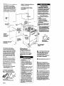
Check location where range will be
installed The range should be located for
convenient use in kitchen
ALL OPENINGS IN THE WALL OR
FLOOR WHERE RANGE IS TO BE IN-
STALLED MUST
BE SEALED.
\
\
\
Important: Observe all ‘\,
governing codes and
ordinances.
Mobile home installation
The installation of tbis range must
conform to the Manufactured Home
Corshuction end Safety Standards, Title
24 CFR, Part 3280 (formerly the Federal
Standard for Mobile Home Conshuction
and Safely. Title 24. HUD, Part 280); or
when such standard is not appltcable.
the Standard for Manufactured Home
Installation 1982 (Manufactured Home
Sites. Communities and Setups), ANSI
A225, l-1987,
orlatest
edItIon. or with
local codes.
When this range Is installed in a mobile
home, it must be secued to the floor
during trsnslt. Any method of securing
the range is adequate as long as it
conform to the standards listed above.
Four-wire power supply cord must be
used in a mobile home installation The
appliance wiring will need to be revised
See Electrical requirements.
Copies of the standards
listed may be obtained from:
l
National Fire Protection Association
Batterymarch Park
Cluincy, Massachusetts 02269
Avold cabinet f&g; above the
cooking surface. If wbfnets 6re
shady histalled, reduce the hazard
of reaching over a heated cooking
surface by InsmIlIng e range hood
The range hood should extend a
minlmnm o! 5 inches out from the
bottom of the cabfneta.
Tools needed
for installation:
Panel
A
Electrical ’
requirements
Save Installation Instructions for
electrical inspector’s use.
A power supply cord is not supplled
with thin producl. but is available
Eouih your local elecuical supply
Electrical Shock Hazard
1 Electrical ground is rewed on
this appliance.
1 Improper connection of the
equipment-gounding conductor
can result in elecuicsl shock.
1 Check with a qualified elect&Ian
if you are in doubt as to whether
the appliance is properly
arounded.
I only a power supply cord kit rated
at 250 volts. 40 ammeres end
investigated for use with ranges
should be used.
1 Do Not use an extension cord with
this appliance. Such use may result
in a fire. electrical shock or other
personal injury.
.~
m Do Not have a fuse in the neutral 01
woundJng cimdt. A fuse in the
neutral or grounding circuit could
result in electrical shock.
1 Do Not plug the “pigtail” power
cord into a live well receptacle
Wore the cord la permanently
connected to the terminal block To
do so may result in pereonal injury
horn elecvical shock.
Failure to follow these fustructions
could result ia an electrical rho& or
personal injury.
Reachiug over a heated cooking
surface could result in a serious burn
or other pe~~cml injuy.
Electrical Shock Hazard
It is the customer’s responsibility:
~TO contact a quaIified eleceical
Installer.
#To assure that electrical
installation is adequate end in
conformance with National
Elect&al Code, ANSWWPA ‘70.
lateat edition’. and all local codee
and ordinances.
Failure to do so could result In fire.
elechicd ahock or other personal
injury.
A
A threewIre or four-wire, single
n
phase, 120/240-volt. GO-Hz, AC
only electrical supply (or tbreewire
or four-wire 120/2O&volt if specified
on seti plate) is requked on a
separate, IO-ampere circuit,
fused
on both sides of the line. A time-delay or
circuit breaker Is recommended
B
THE RANGE MUST BE CONNECTED
n
WfTH COPPERWIRE ONLY.
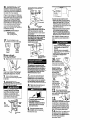
C
Local
codes may permit the
s use of a U.L.-lIsted 250-volt, 40.
ampere range power supply cord (pigtail).
This cord contains three, No.-10 copper
wires and matches a three-wire receptacle
of NEMA Type lo-50R, shown in Figure 1.
Connectors on the appUance end must be
rinQ terminals. A U.L.-listed strain relief
must be provided at tbe point the power
supply cord enters the appliance.
D
The appliance may be connected
n
drectlv to the fused disconnect or
circuit brake; box through flexible,
armored or non-metallic sheathed, copper
cable. Allow two or three feet of slack in
theUnesothatitcanbemovedlf
servicing is ever necessary. A IJ.L.-listed
conduit connector must be provided at
each end of the power supply cable (at
the appliauce and at the junction box).
Wire sizes (COPPER WIRE ONLY) end
conuecUon6 mwt conform with the rating
of the appliance (40 emperes).

E
IF CONNECTING TO A 4-WIFtE
. ELECTRICAL SYSTEM: This
appliance is msnufactured with ground
connected to cabinet. The ground must
be revised so the green grounding wire
of the I-wire power cord is connected to
the osbklet. See 4-w&e elect&al
connection section, Panel c.
When a I-wire receptaole of NEMA type
14-60R is used (See Figure 2) a matching
U.L.- listed, I-wire, 250~volt, IO-ampere.
range power supply cord (pigtall) must be
used. This cord conteins four copper
conductors with ring terminals on the
appliance end, terminating in a NEMA
Type 14.50P plug on the supply end. The
fourth (grounding) conductor roust be
identified by a green or green/yellow
cover and the neu&al conductor by a
white cover. Cord should be Type SPD or
SFlDT with a U.L.-listed snain relief and
he a least four feet long.
The IvXWMUM conductor sizes for
the copper I-wire power cord are:
IO-ampere cfrcult
2. No.-8 conductors
1, No.-10 white neutral
1, No.- 8 green grounding
F
The wiring diagram L also
. located on the back of the range.
Now start...
With range in kitchen.
1
Remove racks
and other parts from
. inside oven
2
.
Place one foot on the
shi~~ina
base. Tilt
range forward slightly tdfee-rear legs.
Gently lower range to floor. Tilt range
backwards until front legs ere free.
3
Remove shipping materiels,
. tape and protective film from range.
Do not remove cardboard shipping base
at tbis the.
4
Adjust the levehng legs
. approximately l/4’ or to a point
where the range base does not touch the
iloor. (If model is so equipped.)
Persona3 lniurv Hazard
Carefully remove he-rear access
nanel when attaching the newer
eupply cord. The rear-acceia panel
contains a counterweight bon
making it heavier than it appears.
Faflure to follow this hast.rnction
may result in personal injury.
J
3-wire electrical connection
See Panel C for I-wire electrical
connection
Take the strsjn relief from the power
supplycordkitandfnsertitintothehole
MOWtbteIUlblblock.hlSertthe
power cord through the snalu relief
allowinuenouahslacktoeasfivattachto
tetminr;ihlook-
Use only r&~-type tetmbds
to oouneu
power supply cord Use 3/V Imass nuul
(provided with the range) to seam the
~~w.‘er m&y cord. Do Not loostm
factory-bstelled nuta already hmtalled
on the t6mnhaL Be sue factory
instelled nuta are tight.
sil”,
tern
nu*
ef md IO-am~ore
This appllauca Is mauufachxed with
neutIal tmlninal
wnuected to the frame.
If local ocdw and ordinancw Do Not
pmmit grounding through the neutral. a
four-wire powar supply oord. rated 250
volts, 40 amperes
and
investigated for use
with ranges must he used. See I-wire
elechicel wnnection, Panel C.
7
Connect the neunal (white)
. wire to the center silver-colored
terminal mew on the terminal block
Connect the other two wires to the outer
Wminalscrewsontheterminalhlo&
Att8ch washers end hex nuts supplied in
the parts packege. Check that nuts are
tight
t0
irwJe proper eleceical
COM~OUOKL
8
Tighten the stmin relief screws or
m conduit connector clamping
screws. Replaze eccess panel
a To prevent tipping, install range
anti-Up bracket.
n Save thew hatallation
Instrwtlons. If range in moved to a
new locatlos the anti-tip bracket
must he removed and reinstalled
In the new location.
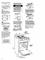
9
ill0 anti-tip bracket must be
. installed. Anti-tip bracket may
befestenedtothefloorundertherangeor
wall ldind tile range.
-
To Install antl-tip bracket on wall:
m Measure and mark a line at the center
of the cabinet opening o* the rear wall.
Measure end mark lines 7-13116’ and
S-16/16’ from either the left (shown) or
right side of the centerbne on the rear
wall Measure and mark on the rear wall
a line 3/E’
from
the floor.
To InstaIl anti-tip bracket on flooc
l
Measure and mark a line at the center
of the cabinet opening on the Soor.
Measure and mark lines 7-13/W and
&36/16’from either the left (shown) or
right side of the centerline on the floor.
Measure and mark on the floor a line 1’
from the rear wall
Note: If there is a cabinet on only one
side, install the autl-Up bracket next to
the cabinet. using the measurements
given
Propeay Damage
1 Contact a qualified insteller for the
best procedure to drill mounting
holes through your type of floor
covering.
1 Before moving range across floor,
check that range is on
shipping
base or slide renae onto cardboard
orhardboard. -
Failure to follow these instructions
may result in damage to floor
covering.
bracket to wood
floor or wall, driJl l/3’
holes at the two motmtmg
screw locations where the two bnes
ere crossed by the third line.
,,
To mount sntl-tip
bracket to concrete or
ceradc floor or wall,
use a masonry drill bit to
ddl l/4’ holes at each
mounting screw
location Tap plastic
anchors km mounting
holes in floor or wall with
a hammer,
11.
Line up holes in
anti-tip
bracket
with holes In floor
or wall Use the
screws provided to
mount the anti-tip
bracket to the floor
or wall
12
Move range close to fineI
n
position. Remove shipping base,
cardboard or herdboard horn under the
range. Plug power supply cord into
grounded outlet.
I II I Ill
13.
Carefully move range
final position Pull bottom of front panel
out and lift up to remove penel. Look
under range (a Saahlight may be needed)
to check that anti-tip bracket overlaps
range base. If anti-tfp bracket does not
overlap base, remove range and
reposition bracket to insure that range
base will fit properly under bracket.
the range to the floor.‘Any method of
securing the range is ad&ate as long
as it conforms to the stauderds l&ted io
the Mobile home installation
instructions, Panel A.

Range must be secured when mobile
home is moved and at all times in a RV.
recreational vehicle using the method
descrlhed.
Pull bottom of front Dane1 out end lift UD
to remove panel. Removing levehng
-
legs.
16
Secure be range using 6/16” bolts,
washers and nuts through the leveling
leg holes. Replace lower access panel.
Skip step 17.
Place rack in oven. Place
n
level on rack, first side to side;
then front to back If range is not level at
the tiont, adjust the leveling legs up or
down until the range is level. If reer of
range needs adjusting, adjust rear
leveling legs up or down until range is
level. If rear legs sre adjusted downward
more than l/8”. add shims under anti-tip
bracket. Replace front panel.
Note: Oven must be level for satisfactory
baking conchtlons.
4-wire electrical connection
Use this wirhg method for mobile homes
and whenever 4-wire installation Fs
required
Personal Injury Hazard
Carefully remove the rear access
panel when attaching the power
supply cord. The rear access panel
contains a counterweight box
making it heavier than it appears.
Failure to follow this h~truction
may result in penonal Lniury.
Take the strain relfef from the
power supply cord kit end insert it
into the hole below the terminal block.
Insert the power supply cable through
the strah relief ellowhg enough slack to
easily attach to the terminal block.
B
Remove the grounding link from
. the terminal block. Remove the
green grounding screw and place it with
your other parts.
To get the most efficient
use from your new Roper range,
read your Roper Use and Care
Guide. Keep Installation
lnatrucrione and Guide close to the
range for easy reference.
5. 6.
7. 8.
--
C
Connect the green grounding
n
wiretotherangeusfngthe
grounding screw removed in Step B. The
green growding wire must be attached
first and must not
contact
any other
.--
D
connect the neutral
(white)
. wire to the center, silver-colored
tmminal screw on the termhal block.
Connect the other two wires to the outer
terminals on the terraInal block. Use ring
type tembals only. Attach washers and
hex nuts
aUDDlied
in the
PUtS Packaee.
Check that dirts ere tight-to tn.&e proper
electrical connection
E
Tighten the strain relief screws.
m Replace access panel.
F
Contluue hstallatIon at Step 9,
m PanelB.
Numbers
correspond
to steps.
13. 14. 15. 16. 17.
Panel C

If range does not
operate...
. Check that the circuit breaker is not
tripped or the fuse blown.
m Check that power supply cord is
plugged into wall receptacle.
I
NOTE:
I
Refer to Use and Care Guide for
operating instructiona and cleaning
iILmuctiolls.
Part No. 76409-W/4315463 Rev. A
&, 1991
For cleaning and
maintenance...
If removing the range is necessary for
deerhgandmaintenan0e,disconnect
elecmd SuPplY.
If ekctdcal supply is inaccessible, lift the
range slightly at the front and pull the
range away from the wall. Pun tb13 range
outonlyasfsras neoessaIytodisoomlect
the eleohic supply line.
$zz.ge to complete cleaning
Move
range back into operating position
Level the range. Reoonneot the eleotdoal
supply. Make sure that anti-tip bracket
Personal ti]urymmduct
Damage Hazard
Do Not step, lean or sit on the range
drawer or door.
Failure
to follow these instruction9
could result in personal injuxy
and/or
product damage.
Benton Harbor, IvWhigau 49022
If you need
assistance...
Call your dealer or local authorized
sexvloe campany. when you oau you will
need the range model number and serial
number. Both numbers can be found on
the sw-ialhting plate located under the
cooktoP.
Prhlted in U.S.A.
-
 1
1
-
 2
2
-
 3
3
-
 4
4
-
 5
5


Whirlpool Roper FEP210VL0 User manual
- Category
- Cookers
- Type
- User manual
- This manual is also suitable for
Ask a question and I''ll find the answer in the document
Finding information in a document is now easier with AI
Related papers
-
Whirlpool 30 eye-level range User manual
-
Whirlpool RF364LXMQ0 Installation guide
-
-
-
KitchenAid 9.76E+13 User manual
-
-
-
-
Whirlpool SF372BEE Q/Z User manual
Other documents
-
Tappan TEF242BU4 Installation guide
-
-
-
Kenmore 66595792000 Installation guide
-
-
-
Electrolux EW30ES65GBG Installation guide
-
Electrolux EW30ES65GSF Installation guide
-
GE JBS15F2CT Owner's manual
-
Frigidaire FEF450BWG Installation guide