
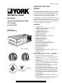
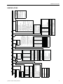
246653-YTG-E-0108
FOR DISTRIBUTION USE ONLY - NOT TO BE USED AT POINT OF RETAIL SALE
TECHNICAL GUIDE
MILLENNIUM
®
SINGLE PACKAGE ROOFTOP UNITS
Y
32, Y33 & Y34
25, 30, & 40 TON
25 TON (10 EER)
30 & 40 TON (9.5 EER)
®
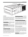
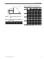
30 TON UNIT SHOWN
ISO 9001
Certified Quality
Management System
TOMORROW’S UNIT TODAY
GENERAL
Introducing the YORK Millennium 25, 30, & 40 ton rooftop
line - units designed to provide peak performance and value
both today and for years to come. Millennium units are manu-
factured at an ISO 9001 registered facility, and each rooftop
is completely computer-run tested prior to shipment.
The Millennium is designed to be flexible enough to meet
your needs today and in the future. The true value of YORK’s
Millennium is that it can be designed to fit any need, from
cooling only, constant volume applications to variable air vol-
ume systems with variable frequency drive.
FEATURING:
• Cooling Only Units
• Cooling/Gas Heating Units (Natural) Standard or
Modulating Gas Heat available
• Cooling/Electric Heating Units
• Cooling/Hot Water Heating Units
• Cooling/Steam Heating Units
• Industry Leading Efficiency
• Double Wall Construction
• Stainless Steel or Powder Coated Drain Pan
• Multiple Scroll Compressors
• Multiple Refrigeration Circuits
• Upgradable Motor Efficiency
• Enhanced Filtration
• Vibration Isolated Supply Fan and Motor
• Technicoated Evaporator and Condenser Coils
• High Capacity Evaporator Coils
• Single Power Point Connection
• Easy Access Hinged Doors
• Variable Air Volume
• Constant Air Volume
• Factory Installed Economizers/Disconnect/Convenience
Outlet/Control Options
•Low Profile
MILLENNIUM SIMPLICITY
®
ELITE™ FEATURES:
• Single Button Programming and LED Display
• Designed to operate on both constant and variable air
volume units
• 365-Day real time clock with automatic Daylight Savings
time adjustment
• Occupancy Schedule allowing two schedules per day
• 20 Holiday schedules with programmable schedules that
can start at any time, day or night
• Patented Comfort Ventilation operation for economical
and comfortable economizer operation
• Demand Ventilation option to assure proper IAQ condi-
tions based on available space or return air CO
2
levels
• Temperature/Humidity programming algorithm allows
programmable limits to help control humidity in the space
• Smoke Purge automatically ventilates the space when
smoke is detected
• Monitors dirty filters and proves airflow before starting
heating or cooling
• Intelligent recovery to bring the space temperature up to
occupied setting quicker and more economically

246653-YTG-E-0108
2 Johnson Controls Unitary Products
TABLE OF CONTENTS
GENERAL . . . . . . . . . . . . . . . . . . . . . . . . . . . . . . . . . . . . . .1
FEATURING . . . . . . . . . . . . . . . . . . . . . . . . . . . . . . . . . . .1
MILLENNIUM SIMPLICITY® ELITE™ FEATURES . . . . .1
OVERVIEW . . . . . . . . . . . . . . . . . . . . . . . . . . . . . . . . . . . . .5
FEATURES AND BENEFITS . . . . . . . . . . . . . . . . . . . . . . .5
INSTALLATION FEATURES . . . . . . . . . . . . . . . . . . . . . .6
CONSTRUCTION FEATURES . . . . . . . . . . . . . . . . . . . .7
LIST OF FEATURES AND BENEFITS . . . . . . . . . . . . . . .8
STANDARD FEATURES . . . . . . . . . . . . . . . . . . . . . . . . . . 8
FACTORY INSTALLED OPTIONS . . . . . . . . . . . . . . . . . . 8
FIELD INSTALLED ACCESSORIES . . . . . . . . . . . . . . . . . 8
NOMENCLATURE . . . . . . . . . . . . . . . . . . . . . . . . . . . . . . . .9
SELECTION PROCEDURE . . . . . . . . . . . . . . . . . . . . . . . .11
SELECT UNIT . . . . . . . . . . . . . . . . . . . . . . . . . . . . . . . .11
SELECT FAN SPEED AND HORSEPOWER
REQUIREMENTS OF SUPPLY AIR FAN . . . . . . . . . . .11
SIZE OVERCURRENT PROTECTION DEVICE AND
DETERMINE CIRCUIT AMPACITY . . . . . . . . . . . . . . . .11
HOT WATER HEATING . . . . . . . . . . . . . . . . . . . . . . . . . .14
PHYSICAL DATA HOT WATER COIL - 1 ROW . . . . . .14
PIPING CONNECTIONS . . . . . . . . . . . . . . . . . . . . . . . .14
PHYSICAL DATA HOT WATER COIL - 2 ROW . . . . . .20
STEAM HEATING . . . . . . . . . . . . . . . . . . . . . . . . . . . . . . .25
PHYSICAL DATA STEAM COIL - 1 ROW . . . . . . . . . . .25
PIPING CONNECTIONS . . . . . . . . . . . . . . . . . . . . . . . .25
SUPPLY AIR DRIVE ADJUSTMENT . . . . . . . . . . . . . . . .28
CFM, STATIC PRESSURE, AND POWER - ALTITUDE
AND TEMPERATURE CORRECTIONS . . . . . . . . . . . .44
GUIDE SPECIFICATIONS - YORK
MILLENNIUM 25, 30, & 40 TON UNITS . . . . . . . . . . . . . . 89
GENERAL . . . . . . . . . . . . . . . . . . . . . . . . . . . . . . . . . . .89
DESCRIPTION . . . . . . . . . . . . . . . . . . . . . . . . . . . . . . . .89
CONSTRUCTION . . . . . . . . . . . . . . . . . . . . . . . . . . . . . .89
BASE . . . . . . . . . . . . . . . . . . . . . . . . . . . . . . . . . . . . . . . . 89
CASING . . . . . . . . . . . . . . . . . . . . . . . . . . . . . . . . . . . . . . 89
SUPPLY AIR SYSTEM . . . . . . . . . . . . . . . . . . . . . . . . . .89
SUPPLY AIR FAN . . . . . . . . . . . . . . . . . . . . . . . . . . . . . . 89
OPTIONAL . . . . . . . . . . . . . . . . . . . . . . . . . . . . . . . . . . . . 89
BEARINGS AND DRIVES . . . . . . . . . . . . . . . . . . . . . . .89
AIR FILTERING SYSTEM . . . . . . . . . . . . . . . . . . . . . . .90
OPTIONAL . . . . . . . . . . . . . . . . . . . . . . . . . . . . . . . . . . . . 90
AIR INLET SYSTEM . . . . . . . . . . . . . . . . . . . . . . . . . . . .90
GENERAL . . . . . . . . . . . . . . . . . . . . . . . . . . . . . . . . . . . . 90
ECONOMIZER (OPTIONAL) . . . . . . . . . . . . . . . . . . . . . . 90
RELIEF SYSTEM (OPTIONAL) . . . . . . . . . . . . . . . . . . . . 90
BAROMETRIC RELIEF (OPTIONAL) . . . . . . . . . . . . . . . 90
EXHAUST AIR FANS (OPTIONAL) . . . . . . . . . . . . . . . . 90
ENERGY RECOVERY VENTILATION
(FIELD INSTALLED OPTION) . . . . . . . . . . . . . . . . . . . . 90
GENERAL . . . . . . . . . . . . . . . . . . . . . . . . . . . . . . . . . . . . 90
HEATING SYSTEM (OPTIONAL) . . . . . . . . . . . . . . . . . 90
GAS-FIRED HEATING SECTION . . . . . . . . . . . . . . . . . . 90
ELECTRIC HEATING SECTION . . . . . . . . . . . . . . . . . . . 91
HOT WATER HEATING COIL . . . . . . . . . . . . . . . . . . . . . 91
STEAM HEATING COIL . . . . . . . . . . . . . . . . . . . . . . . . . 91
REFRIGERATION SYSTEM . . . . . . . . . . . . . . . . . . . . . 91
EVAPORATOR COILS . . . . . . . . . . . . . . . . . . . . . . . . . . 91
COMPRESSORS . . . . . . . . . . . . . . . . . . . . . . . . . . . . . . 92
CONDENSER COILS . . . . . . . . . . . . . . . . . . . . . . . . . . . 92
CONDENSER FANS AND MOTORS . . . . . . . . . . . . . . . 92
REFRIGERANT PIPING . . . . . . . . . . . . . . . . . . . . . . . . . 92
HOT GAS BYPASS (OPTIONAL ON CV; STANDARD
ON VAV) . . . . . . . . . . . . . . . . . . . . . . . . . . . . . . . . . . . . . 92
CONTROLS . . . . . . . . . . . . . . . . . . . . . . . . . . . . . . . . . . 92
GENERAL DESCRIPTION . . . . . . . . . . . . . . . . . . . . . . . 92
COMPRESSOR CONTROL . . . . . . . . . . . . . . . . . . . . . . 92
FAN CONTROL . . . . . . . . . . . . . . . . . . . . . . . . . . . . . . . . 92
EQUIPMENT CONTROL FEATURES . . . . . . . . . . . . . . 93
COMFORT CONTROL FEATURES . . . . . . . . . . . . . . . 93
OPTIONAL COMMUNICATION TRANSLATOR . . . . . . 94
OVERVIEW . . . . . . . . . . . . . . . . . . . . . . . . . . . . . . . . . . . 94
OPTIONAL CONTROL . . . . . . . . . . . . . . . . . . . . . . . . . 95
YORK COMMERCIAL COMFORT SYSTEM (YCCS) . . . 95
AVAILABLE ACCESSORIES . . . . . . . . . . . . . . . . . . . . . 95
PARTIAL PERIMETER ROOF CURBS . . . . . . . . . . . . . . 95
BURGLAR BARS . . . . . . . . . . . . . . . . . . . . . . . . . . . . . . 95
FIELD INSTALLED BAROMETRIC RELIEF . . . . . . . . . . 95
PROGRAMMABLE THERMOSTAT, WITH OR WITHOUT
REMOTE SENSOR (REQUIRED FOR CONSTANT
VOLUME UNITS) . . . . . . . . . . . . . . . . . . . . . . . . . . . . . . 95
REMOTE WALL MOUNTED TEMPERATURE
SENSORS . . . . . . . . . . . . . . . . . . . . . . . . . . . . . . . . . . . . 95
DIRTY FILTER SWITCH . . . . . . . . . . . . . . . . . . . . . . . . . 95
PROPANE CONVERSION KITS . . . . . . . . . . . . . . . . . . . 95
HIGH ALTITUDE CONVERSION KITS . . . . . . . . . . . . . . 95
ENERGY RECOVERY VENTILATORS . . . . . . . . . . . . . 95

246653-YTG-E-0108
Johnson Controls Unitary Products 3
LIST OF FIGURES
Fig.# Pg.#
1 HOT WATER PIPING CROSS-SECTION . . . . . . . . . 15
2 HOT WATER COIL - 25 & 30 TON, 1 ROW,
AT 10 GPM . . . . . . . . . . . . . . . . . . . . . . . . . . . . . . . . . 16
3 HOT WATER COIL - 25 & 30 TON, 1 ROW,
AT 20 GPM . . . . . . . . . . . . . . . . . . . . . . . . . . . . . . . . . 16
4 HOT WATER COIL - 25 & 30 TON, 1 ROW,
AT 30 GPM . . . . . . . . . . . . . . . . . . . . . . . . . . . . . . . . . 17
5 HOT WATER COIL - 25 & 30 TON, 1 ROW,
AT 40 GPM . . . . . . . . . . . . . . . . . . . . . . . . . . . . . . . . . 17
6 HOT WATER COIL - 40 TON, 1 ROW,
AT 10 GPM . . . . . . . . . . . . . . . . . . . . . . . . . . . . . . . . . 18
7 HOT WATER COIL - 40 TON, 1 ROW,
AT 20 GPM . . . . . . . . . . . . . . . . . . . . . . . . . . . . . . . . . 18
8 HOT WATER COIL - 40 TON, 1 ROW,
AT 30 GPM . . . . . . . . . . . . . . . . . . . . . . . . . . . . . . . . . 19
9 HOT WATER COIL - 40 TON, 1 ROW,
AT 40 GPM . . . . . . . . . . . . . . . . . . . . . . . . . . . . . . . . . 19
10 HOT WATER COIL - 25 & 30 TON, 2 ROW,
AT 20 GPM . . . . . . . . . . . . . . . . . . . . . . . . . . . . . . . . . 21
11 HOT WATER COIL - 25 & 30 TON, 2 ROW,
AT 40 GPM . . . . . . . . . . . . . . . . . . . . . . . . . . . . . . . . . 21
12 HOT WATER COIL - 25 & 30 TON, 2 ROW,
AT 60 GPM . . . . . . . . . . . . . . . . . . . . . . . . . . . . . . . . . 22
13 HOT WATER COIL - 25 & 30 TON, 2 ROW,
AT 80 GPM . . . . . . . . . . . . . . . . . . . . . . . . . . . . . . . . . 22
14 HOT WATER COIL - 40 TON, 2 ROW, AT 20 GPM. . 23
15 HOT WATER COIL - 40 TON, 2 ROW, AT 40 GPM. . 23
16 HOT WATER COIL - 40 TON, 2 ROW, AT 60 GPM. . 24
17 HOT WATER COIL - 40 TON, 2 ROW, AT 80 GPM. . 24
Fig.#
Pg.#
18 STEAM PIPING CROSS SECTION . . . . . . . . . . . . . . 25
19 STEAM COIL - 25 & 30 TON, 1 ROW . . . . . . . . . . . . 26
20 STEAM COIL - 40 TON, 1 ROW . . . . . . . . . . . . . . . . 26
21 ALTITUDE/TEMPERATURE CONVERSION
FACTOR . . . . . . . . . . . . . . . . . . . . . . . . . . . . . . . . . . 45
22 FAN PERFORMANCE - 25 TON . . . . . . . . . . . . . . . . 47
23 FAN PERFORMANCE - 30 TON . . . . . . . . . . . . . . . . 49
24 FAN PERFORMANCE - 40 TON . . . . . . . . . . . . . . . . 51
25 POWER EXHAUST - ONE FORWARD CURVE
FAN - 25 TONS . . . . . . . . . . . . . . . . . . . . . . . . . . . . . 58
26 POWER EXHAUST - TWO FORWARD CURVED
FANS - 30 & 40 TONS . . . . . . . . . . . . . . . . . . . . . . . . 60
27 CENTER OF GRAVITY . . . . . . . . . . . . . . . . . . . . . . . 78
28 COMPONENT LOCATION . . . . . . . . . . . . . . . . . . . . 80
29 END RETURN, BOTTOM SUPPLY . . . . . . . . . . . . . . 81
30 BOTTOM SUPPLY AND RETURN . . . . . . . . . . . . . . 82
31 BOTTOM RETURN, FRONT & REAR SUPPLY . . . . 83
32 END RETURN, FRONT & REAR SUPPLY . . . . . . . . 84
33 MILLENNIUM OVERHEAD VIEW . . . . . . . . . . . . . . . 85
34 MILLENNIUM MAJOR COMPONENT LAYOUT . . . . 85
35 MILLENNIUM CABINET DOOR CONFIGURATION . 86
36 CLEARANCES - HOOD/ECONOMIZER & MOTOR
DRIVE - SIDE . . . . . . . . . . . . . . . . . . . . . . . . . . . . . . 87
37 CLEARANCES - HOOD/ECONOMIZER & MOTOR
DRIVE - FRONT & END . . . . . . . . . . . . . . . . . . . . . . 87
38 PARTIAL ROOF CURB MODEL 1RC0455P . . . . . . . 88

246653-YTG-E-0108
4 Johnson Controls Unitary Products
LIST OF TABLES
Tbl.# Pg.#
1 GENERAL PHYSICAL DATA . . . . . . . . . . . . . . . . . . .10
2 REFRIGERANT CHARGE . . . . . . . . . . . . . . . . . . . . .11
3 STANDARD GAS HEATING CAPACITIES . . . . . . . .12
4 TEMPERATURE RISE . . . . . . . . . . . . . . . . . . . . . . . .12
5 MINIMUM HEATING CFM . . . . . . . . . . . . . . . . . . . . .12
6 MODULATING GAS HEATING CAPACITIES . . . . . .12
7 MODULATING HEAT . . . . . . . . . . . . . . . . . . . . . . . . .13
8 ELECTRIC HEATING CAPACITIES . . . . . . . . . . . . . .13
9 WATER PRESSURE DROP (1 ROW,
25 & 30 TON) . . . . . . . . . . . . . . . . . . . . . . . . . . . . . . .14
10 STATIC RESISTANCE HOT WATER COIL
(25 & 30 TON) . . . . . . . . . . . . . . . . . . . . . . . . . . . . . .14
11 HOT WATER COIL (1 ROW, 25 & 30 TON) . . . . . . . .14
12 STATIC RESISTANCE HOT WATER COIL
(1 ROW, 40 TON) . . . . . . . . . . . . . . . . . . . . . . . . . . . .15
13 HOT WATER COIL (1 ROW 40 TON) . . . . . . . . . . . .15
14 WATER PRESSURE DROP (2 ROW,
25 & 30 TON) . . . . . . . . . . . . . . . . . . . . . . . . . . . . . . .20
15 STATIC RESISTANCE HOT WATER COIL
(25 & 30 TON) . . . . . . . . . . . . . . . . . . . . . . . . . . . . . .20
16 HOT WATER COIL (2 ROW, 25 & 30 TON) . . . . . . . .20
17 HOT WATER COIL (2 ROWS, 40 TON) . . . . . . . . . . .20
18 STATIC RESISTANCE HOT WATER COIL
(40 TON) . . . . . . . . . . . . . . . . . . . . . . . . . . . . . . . . . . .20
19 WATER PRESSURE DROP (2 ROW, 40 TON . . . . .20
20 STEAM COIL (1 ROW, 25 & 30 TON) . . . . . . . . . . . .25
21 STATIC RESISTANCE STEAM COIL
(1 ROW, 25 & 30 TON) . . . . . . . . . . . . . . . . . . . . . . . .25
22 STEAM COIL (1 ROW, 40 TON) . . . . . . . . . . . . . . . .25
23 STATIC RESISTANCE STEAM COIL
(1 ROW, 40 TON) . . . . . . . . . . . . . . . . . . . . . . . . . . . .25
24 EXHAUST FAN DRIVE DATA . . . . . . . . . . . . . . . . . .27
25 SUPPLY FAN MOTOR AND DRIVE DATA . . . . . . . .27
26 25 TON DRIVE ADJUSTMENT . . . . . . . . . . . . . . . . .29
27 30 TON DRIVE ADJUSTMENT . . . . . . . . . . . . . . . . .29
28 40 TON DRIVE ADJUSTMENT . . . . . . . . . . . . . . . . .29
29 DRIVE ADJUSTMENT FOR POWER EXHAUST
- 25 TON . . . . . . . . . . . . . . . . . . . . . . . . . . . . . . . . . . .30
30 DRIVE ADJUSTMENT FOR POWER EXHAUST
- 30 & 40 TON . . . . . . . . . . . . . . . . . . . . . . . . . . . . . . .30
31 COOLING PERFORMANCE 25 TON . . . . . . . . . . . . .31
32 COOLING PERFORMANCE 30 TON STANDARD
CAPACITY COIL . . . . . . . . . . . . . . . . . . . . . . . . . . . . .32
33 COOLING PERFORMANCE 30 TON HIGH
CAPACITY COIL . . . . . . . . . . . . . . . . . . . . . . . . . . . . .35
Tbl.#
Pg.#
34 COOLING PERFORMANCE 40 TON STANDARD
CAPACITY COIL . . . . . . . . . . . . . . . . . . . . . . . . . . . . 38
35 COOLING PERFORMANCE 40 TON HIGH
CAPACITY COIL . . . . . . . . . . . . . . . . . . . . . . . . . . . . 41
36 ALTITUDE CORRECTION FACTORS . . . . . . . . . . . . 44
37 FAN PERFORMANCE - 25 TON . . . . . . . . . . . . . . . . 46
38 FAN PERFORMANCE - 30 TON . . . . . . . . . . . . . . . . 48
39 FAN PERFORMANCE - 40 TON . . . . . . . . . . . . . . . . 50
40 FAN PERFORMANCE - 25 & 30 TON AIRFOIL. . . . . 52
41 FAN PERFORMANCE - 40 TON AIRFOIL . . . . . . . . . 54
42 COMPONENT STATIC RESISTANCE. . . . . . . . . . . . 56
43 POWER EXHAUST - ONE FORWARD CURVED
FAN 25 TON . . . . . . . . . . . . . . . . . . . . . . . . . . . . . . . . 57
44 POWER EXHAUST - TWO FORWARD CURVED
FANS - 30 & 40 TON . . . . . . . . . . . . . . . . . . . . . . . . . 59
45 ELECTRICAL DATA 25 TON BASIC UNIT R22 . . . . 61
46 ELECTRICAL DATA 30 TON BASIC UNIT R22 . . . . 61
47 ELECTRICAL DATA 40 TON BASIC UNIT R22 . . . . 62
48 ELECTRICAL DATA 25 TON WITH ELECTRIC
HEAT R22 . . . . . . . . . . . . . . . . . . . . . . . . . . . . . . . . . 63
49 ELECTRICAL DATA 30 TON WITH ELECTRIC
HEAT R22 . . . . . . . . . . . . . . . . . . . . . . . . . . . . . . . . . 64
50 ELECTRICAL DATA 40 TON WITH ELECTRIC
HEAT R22 . . . . . . . . . . . . . . . . . . . . . . . . . . . . . . . . . 65
51 ELECTRICAL DATA 25 TON WITH POWER
EXHAUST R22 . . . . . . . . . . . . . . . . . . . . . . . . . . . . . . 66
52 ELECTRICAL DATA 30 TON WITH POWER
EXHAUST R22 . . . . . . . . . . . . . . . . . . . . . . . . . . . . . . 67
53 ELECTRICAL DATA 40 TON WITH POWER
EXHAUST R22 . . . . . . . . . . . . . . . . . . . . . . . . . . . . . . 68
54 ELECTRICAL DATA 25 TON WITH ELECTRIC HEAT
AND POWER EXHAUST R22 . . . . . . . . . . . . . . . . . . 69
55 ELECTRICAL DATA 30 TON WITH ELECTRIC HEAT
AND POWER EXHAUST R22 . . . . . . . . . . . . . . . . . . 72
56 ELECTRICAL DATA 40 TON WITH ELECTRIC HEAT
AND POWER EXHAUST R22 . . . . . . . . . . . . . . . . . . 75
57 UNIT WEIGHTS . . . . . . . . . . . . . . . . . . . . . . . . . . . . . 78
58 SUPPLY FAN MOTOR VFD WEIGHTS . . . . . . . . . . . 78
59 EXHAUST FAN MOTOR VFD WEIGHTS . . . . . . . . . 78
60 UNIT CENTER OF GRAVITY . . . . . . . . . . . . . . . . . . 78
61 UNIT CORNERWEIGHT . . . . . . . . . . . . . . . . . . . . . . 79
62 INDOOR SOUND POWER RATING . . . . . . . . . . . . . 79
63 ATTENUATION FACTORS . . . . . . . . . . . . . . . . . . . . 79
64 OUTDOOR SOUND POWER RATING . . . . . . . . . . . 79

246653-YTG-E-0108
Johnson Controls Unitary Products 5
YORK Millennium
®
OVERVIEW
Introducing the YORK Millennium 25, 30, & 40 ton rooftop
line - units designed to provide peak performance and value
both today and for years to come. When we asked our cus-
tomers what they wanted in a new rooftop line, we were care-
ful to listen to both the needs of today and tomorrow. So,
you'll find that Millennium units not only help you solve
today's problems, but can handle tomorrow's difficulties as
well:
Industry Leading Efficiency
- The Millennium's 9.5 EER (10
EER 25 ton) rating makes it the most frugal energy consumer
in its class. When it comes to lower operating costs, Millen-
nium simply outperforms the competition.
Double Wall Construction
- Millennium units come double
walled as standard. The galvanized sheet metal liner pro-
vides the best protection against microbial growth, helping
both the unit and the indoor air stay fresh and clean. And, the
rigid sheet metal inner liner keeps the insulation completely
out of the air stream, eliminating concerns about fiberglass
particles.
Drain Pan Whisks Away Condensate
- Condensate is fre-
quently the source of microbial contamination. Competitive
drain pans often are insufficiently sloped to properly drain all
of the condensate, causing drain pan corrosion and bacterial
growth to begin almost immediately. The YORK design is
sloped at the 1/4” per foot recommended by the ASHRAE
62.1-2004 ventilation draft standard, with an extra large drain
connection capable of removing up to three gallons of con-
densate per minute. It is available in either powder coat
painted steel or stainless steel for long life.
Efficient, Durable Scroll Compressors
- The Millennium
design uses industrial grade hermetic scroll compressors for
peak efficiency and low noise operation. The compressor
design is so durable that it can actually hold more liquid
charge without slugging than is present in each refrigerant
circuit at shipment, dramatically reducing the chances of ever
slugging a compressor with liquid charge.
Multiple Refrigeration Circuits for Greater Turndown
- The
YORK Millennium unit has intertwined 10 ton circuits (12.5
ton circuits on the 25 ton) - giving the best unloading capabil-
ity in the industry. With more and more designs requiring
higher outside air quantities, the lower capacity capability is
an outstanding way to neutralize outside air without over-con-
ditioning the space on off-peak days. And, Millennium's high
quality balance-port thermal expansion valves are more
effective at metering refrigerant flow in part-load conditions,
making Millennium a peak-performer across a wide capacity
range.
FEATURES AND BENEFITS
When it comes to flexibility, Millennium really shines. Our cus-
tomers were clear about one thing - not all installations are
the same. Some have very simple needs, others are more
involved. The YORK Millennium serves both markets - and all
of those in between - extremely well. YORK engineers crafted
a design which is both uniquely flexible and competitive, giv-
ing you the best of both worlds. In addition to a competitive
base product, Millennium offers unparalleled flexibility.
Optional features include:
Variable Air Volume
- YORK gives you the ability to vary air
volume by inlet guide vanes or variable frequency drive - the
choice is yours. All Millennium VAV units come standard with
hot gas bypass to give extended operation range.

246653-YTG-E-0108
6 Johnson Controls Unitary Products
Optional Head Pressure Control - For those applications
where mechanical cooling is required below 40°F, optional
low ambient operation allows compressor operation down to
0°F.
Easily Upgrade Motor Efficiency to Meet Tighter Codes
-
Optional high efficiency motors help you make simple
upgrades to meet more demanding building and energy
codes.
Enhanced Filtration Options
- Millennium gives designers the
flexibility to meet various IAQ requirements with a full range
of rigid and throwaway filters at different efficiency levels.
Vibration Isolation
- The Millennium's neoprene mounts are
typically sufficient for most applications but when sound and
vibration transmission are a major concern, YORK offers 1"
and 2" isolation springs for even greater protection from sup-
ply air fan noise and vibration.
Corrosion Resistant Coils
- Many industrial and seacoast
applications require enhanced protection from corrosive envi-
ronments.
Optional TechniCoated Coated Condenser and Evapo-
rator Coils - Many industrial and seacoast applications
require enhanced protection from corrosive environ-
ments. The special dipped phenolic coating process
provides a high level of protection for the exposed con-
denser coil.
Optional Copper-Copper Condenser and Evaporator
Coils - For corrosion resistance.
High Capacity Evaporator Coils
- For those applications
which require slightly more capacity than offered by the stan-
dard Millennium product, YORK offers the option of higher
capacity evaporator coils, boosting cooling output without
increasing unit size. (30 & 40 Ton R-22 only)
Variety of Exhaust Air Options
- YORK Millennium offers a
wide variety of exhaust air options, including barometric
relief, non-modulating power exhaust, and modulating power
exhaust. And, because Millennium units use forward-curved
blowers for power exhaust fans, they can exhaust up to 100%
of the nominal supply air at much greater static pressure
loads than competitive units. Not available on end return.
NOTE: In most applications, the supply fan will keep the
return at negative pressure. A barometric relief will
function better when ducted to building space, not
the return.
Optional Factory Installed Economizers
- Millennium units
offer economizers with Standard or Optional low leak damp-
ers. Comparative enthalpy, single enthalpy and dry bulb con-
trol are available.
Optional Factory Installed Disconnect
- A conveniently
located actuator handle in the front of the unit can disconnect
line power to the entire unit, eliminating the need for a field
provided disconnect. The handle may also be locked in either
position through the use of a standard padlock. Millennium's
single point power connection makes this option particularly
appealing. If desired, the disconnect may be ordered with a
115 volt, GFCI protected convenience outlet, including a fac-
tory wired transformer to power the outlet from the single
point power connection; the convenience outlet remains
operational when the disconnect is open.
Heating Done Your Way
- Millennium offers the choice of nat-
ural gas standard or modulating gas heat, electric resistance
heat, hot water heat, steam, or no heat at all. Very simply, the
choice is yours.
INSTALLATION FEATURES
With YORK Millennium, high performance doesn't mean high
complexity. YORK listened carefully to make sure that Millen-
nium was as simple as possible, and service convenience
comes standard with each unit. From a single curb size to the
easy service access, you'll find that Millennium was designed
to be easy from start to finish.
Full Range of Air Flows and Static Pressures
- The Millen-
nium design gives a complete offering of supply air flows and
static pressure combinations to meet most every application
requirement.
Single Power Point Connection - Millennium units have a sin-
gle gas and electric connection, minimizing time at the job
site. For further installation flexibility, power and gas connec-
tions may be brought up from the curb or through the side of
the unit.
Simple Controls
- Millennium's controls system is easy to
understand and apply, and it doesn't lock you into proprietary
devices. A choice for YORK Millennium today does not limit
your choices tomorrow.
Rain Hoods Rotate Into Place - No bulky, field--installed rain
hoods here. Millennium rain hoods ship rotated inside the
unit. Once on the job, installer merely rotates the hood
upward and puts in a few screws - an easy one-person job.
Excellent Access for Service
- Service access on Millennium
is a snap. Hinged and latched door options give access on
both sides of the unit to all major components. Some doors
have positive action slide latches for even greater ease of
access. All service fittings are conveniently located to mini-
mize time and effort.

246653-YTG-E-0108
Johnson Controls Unitary Products 7
CONSTRUCTION FEATURES
YORK's Millennium rooftop line is built for the long haul, with
high end features and construction offered at a competitive
price. Millennium units are manufactured at an ISO 9001 reg-
istered facility, and each rooftop is completely computer-run
tested prior to shipment. Some of the valuable construction
features of the Millennium which are not found on competitive
units include:
Double Wall Construction
- Each unit has both an exterior
and an interior wall, which make for a more rigid design with
panels and doors that are solid, not flimsy. The unit features a
fully framed construction for even greater stability.
Powder Paint
- Industry leading 1000 salt spray hour paint
keeps the unit in great condition for years to come.
Low Profile
- Millennium units stand only 64” above their
curb, minimizing potential aesthetic conflicts.
Extended flue connection
- Each gas unit ships with a field
mounted external flue. The flue lifts all products of furnace
combustion far above the unit - eliminating the possibility of
corrosion in the furnace heat exchanger from recirculating
flue gases.
Protective Covering
- Special polyurethane sleeves which
cover the distributor tubing keep distributor tubes from con-
tacting each other and wearing out.
Built-in Hail Guard
- Condenser coils angled at 30 degrees
from the vertical are inherently protected from damage due to
shipment, hail, etc.
Induced Draft Furnace
- This design provides a positive
exhaust of all combustion products.
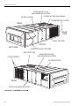
A
NGLED CONDENSER
COILS
PITCHED ROOF
SOLID, CLASS II FAN CONSTRUCTION
INTERTWINED COIL
DOUBLE WALL CONSTRUCTION
LOW LEAK DAMPERS
HINGED, LATCHED
ACCESS DOORS

246653-YTG-E-0108
8 Johnson Controls Unitary Products
LIST OF FEATURES AND BENEFITS
Standard Features
• 9.5 EER (10 EER on 25 ton)
• Double wall construction
• Major components have hinged and latched access
doors
• Industrial duty scroll compressors
• Sturdy framed construction
• Sloped stainless steel or powder coated drain pan
• Separate 10 ton circuits (30 and 40 ton units) or 12.5 ton
(25 ton unit)
• Intertwined evaporator coil
• Angled condenser coils for superior protection
• Single power point connection
• Through-the-curb or through-the-base utility connections
• Retractable outside air hoods
• Powder paint tested to 1000 salt spray hours
• Mechanical cooling from 40° F to 125° F
• 1-1/2” insulation
• Sloped unit roof with drip lip
• High and low refrigerant pressure protection
• Polyurethane sleeves to protect small diameter tubing
• Steel framing around blowers with deflection springs or
rubber isolators for low vibration
• Fully factory packaged and run-tested
• 10 year gas heat exchanger warranty
• One year compressor warranty
• One year warranty on all parts
Factory Installed Options
• Economizer with standard or low leak dampers
• Natural gas standard or modulating gas heat with reli-
able induced draft design
• Electric heat in three sizes
• Variable air volume using either inlet guide vanes, wired
for VFD (variable frequency drive), or factory installed
VFD.
• 1, 2” blower isolator springs or rubber isolators
• A variety of blower horsepower offerings
• High efficiency motors
• High efficiency filtration
• Barometric relief
• Power exhaust of 100% of nominal air flow
• Technicoat corrosive resistant coating on condenser and
evaporator coils
• Copper-Copper corrosive resistant condenser and evap-
orator coils
• 0°F low ambient operation of mechanical cooling
• Hot gas bypass (standard on all VAV units)
• High capacity evaporator coils
• Single unit disconnect
• Convenience outlet and transformer factory wired
• Hot water heating coil with one or two rows
• One row steam heating coil
• Simplicity
®
Elite™ controls
• ModLINC translator
• York Commercial Comfort System (YCCS)
Field Installed Accessories
• 7-Day Programmable Wall Thermostat-Can be used with
or without remote sensors. Can be used on CV and VAV
units when wall thermostat is required for scheduling and
temperature control.
• Energy Recovery Ventilators- 8,000 and 13,000 CFM
models available. Great for applications involving 30% or
more of required outdoor air where energy use and com-
fort must be optimized.
• Wall Sensors- Remote space sensors used with CV or
VAV unit for unit control via the Simplicity® Elite™ con-
trol. Standard sensor, sensor with override and sensor
with override and + 5 degree adjustment.
• Simplicity® Transporter- Device allows internet control
and monitoring of HVAC units equipped with Simplicity®
Elite™ controls.
• Phase Monitor Kit- Includes control and wiring to monitor
and protect the unit from phase reversal, phase loss and
low voltage.
• Burglar Bars- Prevent any type of building entry through
the RTU unit with bars that block the return and supply
openings on downflow applications.
• Partial perimeter roofcurb- Designed for application on
all 25-40 ton Millennium rooftop units. 14" height.
• Barometric Relief Kit- Provides barometric relief hood
and dampers for duct mounting on units requiring end
return.
• Natural Gas to Propane Conversion Kits- Contains ori-
fices and gas valves parts to convert from Natural Gas to
Propane. (Not available on modulating heat.)
• High Altitude Kit- Natural gas kit designed for natural gas
heating applications between 2,000 and 6,000 feet
above sea level.

246653-YTG-E-0108
Johnson Controls Unitary Products 9
NOMENCLATURE
123 4
CONTROL
ADDITIONAL
D = SYNTHESYS CONTROL
CONFIGURATION
VOLTAGE
E = SYNTHESYS CONTROL,
OPTIONS
2 = 208/230-60
DISC., 110V OUTLET
Cu/Cu Condenser Coil
3 = 380-60
F = SYNTHESYS, DISC.
Cu/Cu Evaporator Coil
4 = 460-60
Exhaust VFD (Customer)
5 = 575-60
H = SIMPLICITY CONTROL
(see notes 3 & 7)
7 = 380/415-50
I = SIMPLICITY CONTROL, DISC
NOTES:
110V OUTLET
1. 108KW not available with 208/230V.
J = SIMPLICITY CONTROL,
* Premium Cabinet (6 doors)
2. Standard efficiency motor meets Canadian
DISC, NO 110V OUTLET
* Standard Cabinet (4 doors)
ID BLOWER
(See note 4)
minimum efficiency regulations mandated
K = SIMPLICITY CONTROL W/MODLINC
* Drain Pan - powder coat
A = a, f, i L = d, g, j W = d, e, j
in Canadian Energy Efficiency Regulations.
L = SIMPLICITY CONTROL W/ MODLINC
* Drain Pan - stainless steel
B = a, g, i M = b, f, i X = d, f, h
3. (VFD-CUSTOMER) = Wired for VFD
DISC, 110V OUTLET
C = a, f, j N = b, f, j Y = b, e, h
only; VFD will be customer supplied and
M = SIMPLICITY CONTROL W/MODLINC
*
must
make selections
D = a, g, j O = b, g, i Z = b, e, i
field installed. If VFD Exh is also
DISC, NO 110V OUTLET
N = YCCS CONTROL
P = YCCS CONTROL W/DISC., 110V OUTLET
Q = YCCS ZONING CONTROL
R = YCCS ZONING CONTROL W/DISC.,
110V OUTLET
S = YCCS - VAV CONTROL
T = YCCS - VAV CONTROL W/DISC.,
110V OUTLET
in these options
E = a, e, h P = b, g, j 2 = b, e, j
specified, it will also be cust supplied.
F = a, e, i Q = c, f, i 3 = b, f, h
4. VAV ID Blower requires hot gas bypass .
G = a, e, j R = c, f, j 4 = c, e, h
5. Power exhaust and barometric relief not
H = a, f, h S = c, g, i 6 = c, e, i
available in end return configuration.
CONFIGURATION
I = d, f, i T = c, g, j 7 = c, e, j
6. Air foil fan available on cooling only.
A = 1,2 1 - BOTTOM RETURN
J = d, f, j U = d, e, h 8 = c, f, h
9 = d, g, h
Contact engineering for
B = 1,4 2 - BOTTOM SUPPLY
K = d, g, i V = d, e, i
air foil applications.
C = 1,5
3 - END RETURN
(5)
Air Volume
7. Only available with Hi EFF motors
ECONOMIZER
D = 3,2 4 - REAR SUPPLY
a = CV
A = DUAL ENTH Low leak type
E = 3,4 5 - FRONT SUPPLY
b = VAV (VFD-FACTORY INSTALLED)
B = SINGLE ENTH Low leak type
F = 3,5
c = BYPASS FACTORY VFD
C = DRY BULB ENTH Low leak type
FRONT SUPPLY - COOLING ONLY
d = VAV (VFD-CUSTOMER)
(3)
D = MANUAL Low leak (Not w/PE)
HOT WATER, STEAM & ELECTRIC HEAT -
Fan (See note 6)
E = NONE
BOTTOM SUPPLY ONLY
e = FORWARD CURVE FAN Class I
B = 2,3,5,7 M = 1,3,6,8 X = 2,4,0,7
F = DUAL ENTH Std type
GAS HEAT - BOTTOM OR REAR SUPPLY ONLY
f = FORWARD CURVE FAN Class II
C = 1,4,5,7 N = 2,3,6,8 Y = 1,3,9,8
G = SINGLE ENTH Std type
g = AIR FOIL FAN [always Class II]
D = 2,4,5,7 O = 1,4,6,8 Z = 2,3,9,8
H = DRY BULB Std type
HEAT SOURCE
E = 1,3,6,7 P = 2,4,6,8 2 = 2,4,9,8
N = NATURAL GAS
Blower Mount
F = 2,3,6,7 Q = 1,3,9,7 3 = 1,3,0,8
S = NATURAL GAS, SS HEAT EXCHANGER
h = Neoprene
G = 1,4,6,7 R = 2,3,9,7 4 = 2,3,0,8
EXHAUST
(See note 5)
D = NATURAL GAS, MODULATING HEAT*
i = 1 inch deflection spring
H = 2,4,6,7 S = 1,4,9,7 5 = 1,4,0,8
A = BARO J = 2, 5 S = A, 3
T = NATURAL GAS, MODULATING HEAT, SS *
j = 2 inch deflection spring
I = 1,3,5,8 T = 2,4,9,7 6 = 2,4,0,8
B = 1, 3 K = 2, 6 T = A, 4
HEAT EXCHANGE
R
J = 2,3,5,8 U = 1,3,0,7 7 = 1,4,9,8
C = 1, 4 L = 2, 7 U = A, 5
E = ELECTRIC HEAT
K = 1,4,5,8 V = 2,3,0,7
D = 1, 5 M = 2, 8 V = A, 6
C = COOLING ONLY
9 = Non-Std
E = 1, 6 N = NONE W = A, 7
W = HOT WATER COIL
ID MOTOR
(See note 2)
F = 1, 7 O = 1, 9 X = A, 8
X = STEAM COIL
1 = 10 HP STD
Condenser Coil Head Press. Ctrl.
G = 1, 8 P = 1, 0 Y = A, 9
2 = 15 HP STD
1 = STANDARD 7 = YES
H = 2, 3 Q = 2, 9 Z = A, 0
3 = 20 HP STD
2 = TECHNICOAT 8 = NO
I = 2, 4 R = 2, 0 2 = 8,000 CFM ERV
HEAT CAPACITY
4 = 25 HP STD (Except 25T)
Piping
(See note 4)
3 = 13,000 CFM ERV
3 = 267 MBH
5 = 10 HI-EFF
3 = STANDARD 4 = HOT GAS BYPASS
5 = 533 MBH
6 = 15 HI-EFF
Evaporator Coil
9 = Non Std Config
8 = 800 MBH (40T ONLY)
7 = 20 HI-EFF
5 = STANDARD
Power Exhaust
4 = 40 KW
8 = 25 HI-EFF (Except 25T)
6 = HI-CAP (30T/40T R22 ONLY)
1 = MODULATING DAMPERS A = VFD MODULATING
MOTOR
8 = 80 KW
9 = 7.5 HP STD (25T Only)
9 = STD W/TECHNICOAT
2 = NON-MOD. (ON/OFF)
1 = 108 KW
(1)
0 = 7.5 HI-EFF (25T Only)
0 = HI-CAP W/T-COAT (30T/40T R22)
0 (ZERO) NO HEAT
Motor
1 = 1 ROW
0 = 5 HP HI-EFF (25T Only) 9 = 5 HP (25T Only)
2 = 2 ROW
3 = 7.5 HP 6 = 7.5 HP HI-EFF
1 = 1 ROW
4 = 10 HP 7 = 10 HP HI-EFF
5 = 15 HP (Except 25 Ton) 8 = 15 HP HI-EFF (Except 25 Ton)
Config
A
13
D
14
W = 1,4,0,7
3
3
N
5
A
4
PACKAGE
3
6
4
7
FILTERS
C
12
B
8
1
9
A
10
A
11
GENERATION
3
2
Y
1
Y = York Brand R22
A = STAND.
B = 65%
C = 95%
D = 2" HI-EFF
A = 1,3,5,7
REFRIGERATION
(30T/40T)
3 = 30 TON
4 = 40 TON
2 = 25 TON
L = 2,4,5,8
BASIC UNIT
Class I blower is limited to 15HP in 25/30Ton
Class I blower is limited to 20HP in 40Ton
Class II blowers are not HP limited

246653-YTG-E-0108
10 Johnson Controls Unitary Products
* Unit Control Board with 3 heating outputs only, all other Unit Control Boards 2/1.
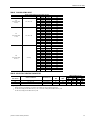
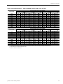
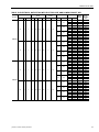
TABLE 1: GENERAL PHYSICAL DATA
UNIT SIZE 25 TON 30 TON 40 TON
U
NIT EER / IPLV
(S
TANDARD CAPACITY EVAPORATOR)
10.0 / 10.92 9.5 / 10.97 9.5 / 9.73
C
OMPRESSOR DATA
NUMBER/SIZE 2 x 12.5 Ton 3 x 10 Ton 4 x 10 Ton
T
YPE Scroll Scroll Scroll
U
NIT CAPACITY STEPS 50%, 100% 33%, 67%, 100% 25%, 50%, 75%, 100%
I
NDOOR FAN AND DRIVE
NUMBER / TYPE 1 / FC 1 / FC 1 / FC
D
IAMETER X WIDTH (INCHES) 22 x20 22 x 20 25 x 22
HP R
ANGE 7.5 - 20 10 - 25 10 - 25
CFM R
ANGE (FULL LOAD) 6,000 - 12,500 6,000 - 15,000 8,000 - 18,000
ESP R
ANGE 0.2” - 4.0” 0.2" - 4.0” 0.2" - 4.0"
E
XHAUST FAN
NUMBER/SIZE/TYPE 1/FC 2/FC 2/FC
HP R
ANGE (SINGLE MOTOR) 5 - 10 7.5 - 15 7.5 - 15
CFM 3,000 - 9,000 4,000 - 18,000 4,000 - 18,000
S
TANDARD EVAPORATOR COIL
SIZE (SQ. FT.) 26.0 26.0 30.4
R
OWS/FPI 3 / 13 3 / 16 4 / 13
H
IGH CAPACITY EVAPORATOR COIL
SIZE (SQ. FT.) 26.0 26.0 30.4
R
OWS/FPI 2/16 4 / 16 4 / 16
C
ONDENSER COIL
SIZE (SQ. FT.) 52.0 48.8 65.0
R
OWS/FPI 2/16 2 /16 2 /16
C
ONDENSER FANS
QUANTITY / DIAMETER (INCHES) 4 / 24 3 / 24 4 / 24
N
OMINAL CFM 4,600 6,800 6,800
M
OTOR HP 3 / 4 1.0 1.0
E
LECTRIC HEAT
K
W RANGE 40 - 108 40 - 108 40 - 108
40
KW 111
80
AND 108 KW / CAPACITY STEPS (CV/VAV) 2 / 1 2 / 1 2 / 1
N
ATURAL GAS HEAT
UNIT SIZE 25 TON 30 TON 40 TON
267 MBH C
APACITY STEPS (CV/VAV) 1 / 1 1 / 1 1 / 1
533 MBH C
APACITY STEPS (CV/VAV) 2 / 1 2 / 1 2 / 1
800 MBH C
APACITY STEPS (CV/VAV) --3 / 1*
267 MBH “M
ODULATING” CAPACITY STEPS (CV ONLY) 6 / 1 6 / 1 6 / 1
533 MBH “M
ODULATING” CAPACITY STEPS (CV ONLY) 12 / 2 12 / 2 12 / 2
800 MBH “M
ODULATING” CAPACITY STEPS (CV ONLY) --17 / 3
H
OT WATER COIL
SIZE (INCHES) 22.5” x 65” 22.5" X 65” 22.5" X 65”
C
APACITY 25 Ton 30 Ton 40 Ton
S
TEAM COIL
SIZE (INCHES) 21" X 65"
T
YPE Steam Coil
F
ILTERS 2" TA
N
UMBER / SIZE 4 / 16 x 25 & 6 / 20 x 25 4 / 16 x 25 & 6 / 20 x 25 4 / 16 x 25 & 6 / 20 x 25
F
ACE AREA (SQ. FT.) 30.4 30.4 30.4
F
ILTERS 2" PLEATED, 30%
N
UMBER / SIZE 4 / 16 x 25 & 6 / 20 x 25 4 / 16 x 25 & 6 / 20 x 25 4 / 16 x 25 & 6 / 20 x 25
F
ACE AREA (SQ. FT.) 30.4 30.4 30.4
F
ILTERS 65% RIGID W/ 2” TA PREFILTERS
NUMBER / SIZE 4 / 16 x 25 & 6 / 20 x 25 4 /16 x 25 & 6 / 20 x 25 4 / 16 x 25 & 6 / 20 x 25
F
ACE AREA (SQ. FT.) 30.4 30.4 30.4
F
ILTERS 95% RIGID W/ 2” TA PREFILTERS
NUMBER / SIZE 4 ea. 16 x 25 / 6 ea. 20 x 25 4 ea. 16 x 25 / 6 ea. 20 x 25 4 ea. 16 x 25 / 6 ea. 20 x 25
F
ACE AREA (SQ. FT.) 30.4 30.4 30.4

246653-YTG-E-0108
Johnson Controls Unitary Products 11
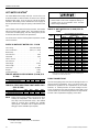
SELECTION PROCEDURE
GIVEN:
Required Cooling Capacity 460,000 Btuh
Required Sensible Cooling 390,000 Btuh
Required Heating (Gas) 320,000 Btuh
Entering Air on Evaporator 83° F DB/ 67° F WB
Outside Design Temperature 95° F
Supply Fan CFM 13,000 CFM
External Static Pressure 1.25 IWG
Electrical Supply Voltage 460-3-60
Economizer Required
2” Throw Away Filters
Constant Volume
SELECT UNIT:
1. Determine nominal tons:
460,000 / 12,000 = 38.33 Tons
Thus, a nominal 40 ton unit is selected.
2. Reference Cooling Capacity Table for a 40 ton unit with
standard evaporator coil.
a. Locate the table for a standard evaporator coil with
95° F air on the condenser.
b. Enter table at 13,000 CFM and 67°F WB air on
evaporator
c. Trace to 83° F Entering Dry Bulb column.
d. Read 493 MBH total capacity and 403 MBH sensi-
ble capacity.
The 40 ton unit will meet the cooling requirements. From
the nomenclature, the unit will be a Y34. Choose the
appropriate configuration for the next digit. Assuming
bottom return and supply, the fourth digit would be an
“A,” making the model Y34A.
3. Find Gas Heating Capacity Table.
a. Trace down Output column.
b. Find output which exceeds 320,000 Btuh require-
ment. The N5 option gives 426 MBH output.
c. Ensure that it is offered in the Y34 unit. Read option
model as N5.
From the basic nomenclature, the model now becomes
Y34AN5. Add voltage code of “4” for 460-3-60. Nomen-
clature becomes Y34AN54.
SELECT FAN SPEED AND HORSEPOWER
REQUIREMENTS OF SUPPLY AIR FAN
1. Find Supply Air Performance Tables for the 40 ton unit.
a. Check footnotes and make necessary additions or
deductions to static resistance of ductwork:
Ductwork static resistance 1.25 IWG
Economizer static resistance addition
(interpolate) =.25 IWG + Gas Heat (High) = 0.5 IWG
Total Static Resistance 2.0 IWG
b. Enter Fan Performance Table at 13,000 CFM and
2.0 IWG static pressure:
RPM = 690
BHP = 10.7
NOTE: Either a Class I or Class II blower could be used.
c. Enter the Fan Motor Drive Tables. Selecting a 15 hp
motor allows (service factor of 1.5) for a maximum
operating BHP greater than the 10.7 BHP require-
ment.
SIZE OVERCURRENT PROTECTION DEVICE AND
DETERMINE CIRCUIT AMPACITY
1. Find electrical tables for the basic 40 ton unit.
a. Enter table for 460-3-60 voltage.
b. Find 15 hp in the Supply Air Fan column.
c. Trace to Minimum Circuit Ampacity column - read
104.
d. Trace to Max. Fuse/Breaker Size column - read 110.
e. Size wire and overprotection device accordingly.
f. Check all footnotes.
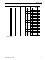
TABLE 2: REFRIGERANT CHARGE
UNIT (TONS) MODEL TYPE
F
ACTORY/ FIELD
C
HARGED
CHARGE
SYS #1 SYS #2 SYS #3 SYS #4
25 wo/HGBP R22 Factory 25 lb. / 8 oz. 26lb / 0oz - -
25 w/HGBP R22 Factory 26 lb. / 0 oz. 26 lb. / 0oz - -
30 wo/HGBP R22 Factory 13 lb. / 4 oz. 13 lb. / 8 oz. 13 lb. / 8 oz. -
30
wo/HGBP
1
R22 Factory 14 lb. / 6 oz. 14 lb. / 10 oz. 14 lb. / 10 oz. -
30 w/HGBP R22 Factory 14 lb. / 0 oz. 13 lb. / 8 oz. 13 lb. / 8 oz. -
30 w/HGBP
1
R22 Factory 15 lb. / 2 oz. 14 lb. / 10 oz. 14 lb. / 10 oz. -
40 wo/HGBP R22 Factory 15 lb. / 5 oz. 15 lb. / 4 oz. 15 lb. / 5 oz. 15 lb. / 15 oz.
40 w/HGBP R22 Factory 15 lb. / 13 oz. 15 lb. / 4 oz. 15 lb. / 5 oz. 15 lb. / 15 oz.
1.
With high capacity evaporator coil.

246653-YTG-E-0108
12 Johnson Controls Unitary Products
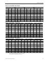
TABLE 3: STANDARD GAS HEATING CAPACITIES
GAS HEAT
O
PTION
AVAILABLE ON
M
ODELS
INPUT CAPACITY (MBH)
1
1.
Heating capacity is only staged on CV models. VAV models use only one stage at full capacity.
O
UTPUT
C
APACITY
(MBH)
2
2.
Blower motor heat not included.
G
AS RATE, CU. FT./HR.
3
3.
Based on a heat content of 1075 Btu/Ft.
3
1ST STAGE TOTAL 1ST STAGE TOTAL
N3 Y32/Y33/Y34 267 267 213 247 247
N5 Y32/Y33/Y34 267 533 426 247 495
N8 Y34 ONLY 267
4
4.
Unit Control Board with 3 heating outputs only. For all other Unit Control Boards the 1st Stage is 533 MBH.
800 638 247 742
TABLE 4: TEMPERATURE RISE
TON
MODULES
123
25 5-35 25-55 -
30 5-35 20-50 -
40 5-30 10-45 25-55
TABLE 5: MINIMUM HEATING CFM
TON
MODULES
123
25 5,644 7,183 -
30 5,644 7,901 -
40 6,584 8,779 13,169
TABLE 6: MODULATING GAS HEATING CAPACITIES
GAS HEAT OPTION
AVAILABLE ON
M
ODELS
INPUT CAPACITY (MBH)
STEPS
O
UTPUT CAPACITY
(MBH)
1
1.
Output Capacity at Full Fire.
G
AS RATE, CU. FT./HR.
M
INIMUM MAXIMUM MINIMUM MAXIMUM
D3
2
2.
Modulating Gas Heat available on CV models only.
Y32/Y33/Y34 69 267 6 213 64 247
D5
2
Y32/Y33/Y34 69 533 12 426 64 495
D8
2
Y34 ONLY 69 800 17 638 64 744

246653-YTG-E-0108
Johnson Controls Unitary Products 13
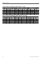
TABLE 7: MODULATING HEAT
STAGES OF GAS CONTROL (% OF FULL HEAT OUTPUT)
G
AS HEAT OPTION AVAILABLE ON MODELS STEP INPUT OUTPUT % OF TOTAL OUTPUT
D3
(Turn down ration
3.8 to 1)
Y32, Y33, Y34
1 69,333 55,466 26%
2 106,666 85,333 40%
3 165,332 132,266 62%
4 202,665 162,132 76%
5 229,332 183,466 86%
6 266,666 213,333 100%
D5
(Turn down ration
7.7 to 1)
Y32, Y33, Y34
1 69,333 55,466 13%
2 106,666 85,333 20%
3 165,332 132,266 31%
4 202,665 162,132 38%
5 229,332 183,466 43%
6 266,666 213,333 50%
7 325,331 260,265 61%
8 362,664 290,132 68%
9 389,331 311,465 73%
10 426,664 341,331 80%
11 495,997 396,798 93%
12 533,330 426,664 100%
D8
(Turn down ration
11.5 to 1)
Y34 Only
1 69,333 55,466 9%
2 106,666 85,333 13%
3 165,332 132,266 21%
4 202,665 162,132 25%
5 229,332 183,466 29%
6 266,666 213,333 33%
7 325,331 260,265 41%
8 362,664 290,132 45%
9 389,331 311,465 49%
10 426,664 341,331 53%
11 495,997 396,798 62%
12 533,330 426,664 67%
13 586,663 469,330 73%
14 655,996 524,797 82%
15 693,329 554,663 87%
16 762,662 610,130 95%
17 799,995 639,996 100%
TABLE 8: ELECTRIC HEATING CAPACITIES
ELECTRIC
HEAT OPTION
AVAILABLE ON MODELS RATED VOLTAGE
NOMINAL
KW
N
OMINAL
MBH
1
1.
Supply air fan motor heat not included.
MBH
AND KW PER STAGE
2
2.
Heating capacity is only staged on CV models. VAV models use only one stage at full capacity.
S
TAGE 1STAGE 2
KW MBH KW MBH
E4 Y32, Y33, Y34 240
3
/480
4
/575
3.
For 208 volts, multiply kW and MBH values by .751. For 230 volts, multiply kW and MBH values by .918
4.
For 460 volts, multiply kW and MBH values by .918.
40 137 40 137 0 0
E8 Y32, Y33, Y34 240
2
/480
3
/575 80 273 40 137 40 136
E1 Y32, Y33, Y34 (460 & 575 volt only) 480
3
/575 108 369 72 246 36 123

246653-YTG-E-0108
14 Johnson Controls Unitary Products
HOT WATER HEATING
1
The YORK Millennium Rooftop units (30 - 40 Ton sizes) can
be furnished with a YORK hot water coil as the source of heat
(Bottom Supply Only). A one or two row coil will be factory
installed in the heating section downstream of the supply air
fan and just above the supply air opening in the bottom of the
unit.
The hot water control valve will not be provided. The installer
will need to field supply a water valve. The installer must also
connect the hot water piping, and valve wiring at the job site
for the hot water heat section to be operational.
For all hot water coils the entering water temperature should
not exceed 200°F.
PHYSICAL DATA HOT WATER COIL - 1 ROW
Coil Casing . . . . . . . . . . . . . . . . . . . . Galvanized Steel
Coil Construction. . . . . . . . . . . . . . . . Al Fin / Cu. Tube
Rows Deep . . . . . . . . . . . . . . . . . . . . . . . . . . . . . . . . 1
Fin Thickness . . . . . . . . . . . . . . . . . . . . . . . . . . . .006”
Tube Wall . . . . . . . . . . . . . . . . . . . . . . . . . . . . . . .016”
Tubes / Circuit. . . . . . . . . . . . . . . . . . . . . . . . . . . . . . 2
Fins Per Inch. . . . . . . . . . . . . . . . . . . . . . . . . . . . . . . 8
Tubes High . . . . . . . . . . . . . . . . . . . . . . . . . . . . 22.50”
Tube Length . . . . . . . . . . . . . . . . . . . . . . . . . . . . . .65”
Face Area . . . . . . . . . . . . . . . . . . . . . . . . . . . .10.16ft.
2
Weight. . . . . . . . . . . . . . . . . . . . . . . . . . . . . . . . .71lbs.
Operating Weight . . . . . . . . . . . . . . . . . . . . . . . .83lbs.
NOTE: Water pressure drop numbers are based on 60°F
entering air temperature, 2.00” maximum air pres-
sure drop across the hot water coil(s). ARI certified
ratings at covering other conditions are available
upon request. Hot water coils are approved for use
with glycol (rates available upon request).
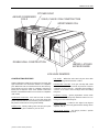
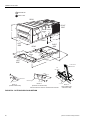
PIPING CONNECTIONS
The hot water piping must enter the unit through the floor of
the heat section compartment. The access doors to the com-
partment are gasketed so the compartment can be sealed.
However, as added protection for water leakage into the
space, the piping access holes should be sealed with a heat
resistant mastic (see the following illustration for approximate
location of the compartment and piping connections.
1. Hot water, steam or electric heat is not available for
front or rear supply.
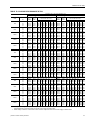
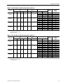
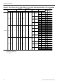
TABLE 9: WATER PRESSURE DROP (1 ROW, 25 &
30 TON)
GPM 102030 40
W
ATER PRESSURE DROP 0.9 3.0 6.0 10.0
TABLE 10: STATIC RESISTANCE HOT WATER COIL
(25 & 30 TON)
CFM 6000 8000 10000 15000
A
IR PRESSURE DROP 1 ROW 0.07 0.11 0.16 0.32
A
IR PRESSURE DROP 2 ROW 0.14 0.23 0.33 0.65
DO NOT use tin based solder. Brazing with tin
based solder could cause equipment damage or
possible injury to OCCUPANTS of the structure
that is being conditioned.
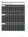
TABLE 11: HOT WATER COIL (1 ROW, 25 & 30
TON)
1
1.
Based on 60°F entering air temperature, 2.00” maximum pres-
sure drop across the hot water coil.
GPM CFM
C
APACITY (MBH) AT ENTERING WATER
T
EMPERATURE
140 °F 160 °F 180 °F 200 °F
10
6000 91.4 115.3 139.3 163.6
8000 102 128.8 155.8 182.9
10000 110.4 139.5 168.8 198.4
12000 117.3 148.4 179.6 211.2
15000 125.9 159.2 192.9 226.9
20
6000 103 129.4 156 182.7
8000 116.8 147 177.2 207.7
10000 128.2 161.3 194.7 228.2
12000 137.8 173.6 209.5 245.6
15000 150 189 228.2 267.8
30
6000 107.6 135 162.5 190.1
8000 122.8 154.3 185.8 217.5
10000 135.5 170.3 205.1 240.2
12000 146.4 184 221.8 259.7
15000 160.3 201.6 243 284.8
40
6000 110.1 138 166 194.1
8000 126.1 158.2 190.5 222.8
10000 139.6 175.2 210.9 246.8
12000 151.2 189.8 228.5 267.5
15000 166.1 208.6 251.3 294.1

246653-YTG-E-0108
Johnson Controls Unitary Products 15
FIGURE 1 - HOT WATER PIPING CROSS-SEC-
TION
TABLE 12: STATIC RESISTANCE HOT WATER COIL
(1 ROW, 40 TON)
CFM 8000 11000 14000 20000
A
IR PRESSURE DROP 1 ROW 0.11 0.19 0.29 0.52
A
IR PRESSURE DROP 2 ROW 0.23 0.39 0.58 1.06
HOT WATER
COIL
CONDENSING
SECTION
INLET (2")
OUTLET (2")
C
L
2.55"
8.38"
2.25"
11.88"
26"
15.8"
88.75"
HEAT SECTION
COMPARTMENT
(1 OR 2 ROW)
OUTSIDE OF
BASE RAIL
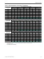
TABLE 13: HOT WATER COIL (1 ROW 40 TON)
1
1.
Based on 60°F entering air temperature, 2.00” maximum pres-
sure drop across the hot water coil.
GPM CFM
C
APACITY (MBH) AT ENTERING WATER
T
EMPERATURE
140 °F 160 °F 180 °F 200 °F
10
8000 102 128.8 155.8 182.9
11000 114 144.1 174.4 205.1
14000 123.2 155.9 188.8 222.1
17000 130.6 165.4 200.4 235.8
20000 136.8 173.3 210.1 247.3
20
8000 116.8 147 177.2 207.7
11000 133.2 167.7 202.3 237.2
14000 146.2 184.2 222.4 260.8
17000 157 197.9 239 280.5
20000 166.2 209.6 253.2 297.3
30
8000 122.8 154.3 185.8 217.5
11000 141.2 177.4 213.8 250.3
14000 155.9 196.1 236.4 276.9
17000 168.3 211.8 255.4 299.3
20000 179.1 225.3 271.8 318.6
40
8000 126.1 158.2 190.5 222.8
11000 145.6 182.7 220 257.5
14000 161.4 202.6 244.1 285.8
17000 174.7 219.5 264.5 309.7
20000 186.3 234.2 282.3 330.6

246653-YTG-E-0108
16 Johnson Controls Unitary Products
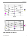
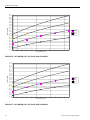
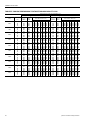
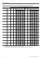
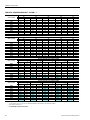
FIGURE 2 - HOT WATER COIL - 25 & 30 TON, 1 ROW, AT 10 GPM
FIGURE 3 - HOT WATER COIL - 25 & 30 TON, 1 ROW, AT 20 GPM
80.0
90.0
100.0
110.0
120.0
130.0
140.0
150.0
160.0
170.0
180.0
190.0
200.0
210.0
220.0
230.0
6000 7000 8000 9000 10000 11000 12000 13000 14000 15000
FLOW RATE (CFM)
CAPACITY (MBH)
140 °F
160 °F
180 °F
200 °F
90.0
100.0
110.0
120.0
130.0
140.0
150.0
160.0
170.0
180.0
190.0
200.0
210.0
220.0
230.0
240.0
250.0
260.0
270.0
6000 7000 8000 9000 10000 11000 12000 13000 14000 15000
FLOW RATE (CFM)
CAPACITY (MBH)
140 °F
160 °F
180 °F
200 °F

246653-YTG-E-0108
Johnson Controls Unitary Products 17
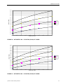
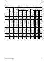
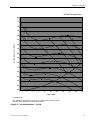
FIGURE 4 - HOT WATER COIL - 25 & 30 TON, 1 ROW, AT 30 GPM
FIGURE 5 - HOT WATER COIL - 25 & 30 TON, 1 ROW, AT 40 GPM
100.0
110.0
120.0
130.0
140.0
150.0
160.0
170.0
180.0
190.0
200.0
210.0
220.0
230.0
240.0
250.0
260.0
270.0
280.0
290.0
6000 7000 8000 9000 10000 11000 12000 13000 14000 15000
FLOW RATE (CFM)
CAPACITY (MBH)
140 °F
160 °F
180 °F
200 °F
100.0
110.0
120.0
130.0
140.0
150.0
160.0
170.0
180.0
190.0
200.0
210.0
220.0
230.0
240.0
250.0
260.0
270.0
280.0
290.0
300.0
6000 7000 8000 9000 10000 11000 12000 13000 14000 15000
FLOW RATE (CFM)
CAPACITY (MBH)
140 °F
160 °F
180 °F
200 °F

246653-YTG-E-0108
18 Johnson Controls Unitary Products
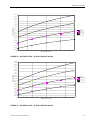
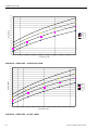
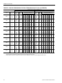
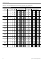
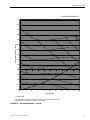
FIGURE 6 - HOT WATER COIL - 40 TON, 1 ROW, AT 10 GPM
FIGURE 7 - HOT WATER COIL - 40 TON, 1 ROW, AT 20 GPM
90.0
100.0
110.0
120.0
130.0
140.0
150.0
160.0
170.0
180.0
190.0
200.0
210.0
220.0
230.0
240.0
250.0
8000 9000 10000 11000 12000 13000 14000 15000 16000 17000 18000 19000 20000
FLOW RATE (CFM)
CAPACITY (MBH)
140 °F
160 °F
180 °F
200 °F
100.0
110.0
120.0
130.0
140.0
150.0
160.0
170.0
180.0
190.0
200.0
210.0
220.0
230.0
240.0
250.0
260.0
270.0
280.0
290.0
300.0
8000 9000 10000 11000 12000 13000 14000 15000 16000 17000 18000 19000 20000
FLOW RATE (CFM)
CAPACITY (MBH)
140 °F
160 °F
180 °F
200 °F

246653-YTG-E-0108
Johnson Controls Unitary Products 19
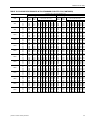
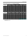
FIGURE 8 - HOT WATER COIL - 40 TON, 1 ROW, AT 30 GPM
FIGURE 9 - HOT WATER COIL - 40 TON, 1 ROW, AT 40 GPM
110.0
120.0
130.0
140.0
150.0
160.0
170.0
180.0
190.0
200.0
210.0
220.0
230.0
240.0
250.0
260.0
270.0
280.0
290.0
300.0
310.0
320.0
8000 9000 10000 11000 12000 13000 14000 15000 16000 17000 18000 19000 20000
FLOW RATE (CFM)
CAPACITY (MBH)
140 °F
160 °F
180 °F
200 °F
120.0
130.0
140.0
150.0
160.0
170.0
180.0
190.0
200.0
210.0
220.0
230.0
240.0
250.0
260.0
270.0
280.0
290.0
300.0
310.0
320.0
330.0
340.0
8000 9000 10000 11000 12000 13000 14000 15000 16000 17000 18000 19000 20000
FLOW RATE (CFM)
CAPACITY (MBH)
140 °F
160 °F
180 °F
200 °F

246653-YTG-E-0108
20 Johnson Controls Unitary Products
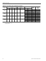
PHYSICAL DATA HOT WATER COIL - 2 ROW
Coil Casing . . . . . . . . . . . . . . . . . . . . Galvanized Steel
Coil Construction. . . . . . . . . . . . . . . . Al Fin / Cu. Tube
Rows Deep . . . . . . . . . . . . . . . . . . . . . . . . . . . . . . . . 2
Fin Thickness . . . . . . . . . . . . . . . . . . . . . . . . . . . .006”
Tube Wall . . . . . . . . . . . . . . . . . . . . . . . . . . . . . . .016”
Tubes / Circuit . . . . . . . . . . . . . . . . . . . . . . . . . . . . . 2
Fins Per Inch. . . . . . . . . . . . . . . . . . . . . . . . . . . . . . . 8
Tubes High . . . . . . . . . . . . . . . . . . . . . . . . . . . . 22.50”
Tube Length . . . . . . . . . . . . . . . . . . . . . . . . . . . . . .65”
Face Area . . . . . . . . . . . . . . . . . . . . . . . . . . . 10.16 ft.
2
Weight. . . . . . . . . . . . . . . . . . . . . . . . . . . . . . . . .90 lbs
Operating Weight . . . . . . . . . . . . . . . . . . . . . . .110 lbs
NOTE: Water pressure drop numbers are based on 60°F
entering air temperature, 2.00” maximum air pres-
sure drop across the hot water coil(s). ARI certified
ratings at covering other conditions are available
upon request. Hot water coils are approved for use
with glycol (rates available upon request.)
1.
Based on 60°F entering air temperature, 2.00” maximum pres-
sure drop across the hot water coil.
TABLE 14: WATER PRESSURE DROP (2 ROW, 25 &
30 TON)
GPM20406080
W
ATER
P
RESSURE
D
ROP
0.9 3.0 6.0 10.0
TABLE 15: STATIC RESISTANCE HOT WATER COIL
(25 & 30 TON)
CFM 6000 8000 10000 15000
A
IR PRESSURE DROP
1 R
OW
0.07 0.11 0.16 0.32
A
IR PRESSURE DROP
2 R
OW
0.14 0.23 0.33 0.65
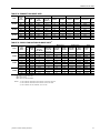
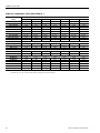
TABLE 16: HOT WATER COIL (2 ROW, 25 & 30
TON)
1
GPM CFM
C
APACITY (MBH) AT ENTERING WATER TEMPERATURE
140 °F 160 °F 180 °F 200 °F
20
6000 177.5 223.8 270.4 317.3
8000 203.8 257.2 311.1 365.5
10000 224.8 284.1 343.9 404.2
12000 242.2 306.4 371.1 436.4
15000 263.6 333.8 404.6 476.1
40
6000 198.1 248.9 300.0 351.3
8000 232.2 292.0 352.2 412.7
10000 260.7 328.1 395.9 464.1
12000 285.0 359.0 433.4 508.3
15000 316.0 398.4 481.3 564.8
60
6000 206.1 258.7 311.4 364.2
8000 243.6 305.9 368.4 431.1
10000 275.3 345.9 416.8 488.0
12000 302.9 380.7 458.9 537.6
15000 338.4 425.7 513.4 601.7
80
6000 210.5 263.9 317.4 371.1
8000 249.8 313.3 377.1 441.1
10000 283.3 355.6 428.2 501.0
12000 312.7 392.7 473.0 553.6
15000 351.0 440.9 531.3 622.1
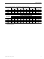
TABLE 17: HOT WATER COIL (2 ROWS, 40 TON)
1
1.
Based on 60°F entering air temperature, 2.00” maximum air
pressure drop across the hot water coil.
ARI certified ratings at other conditions available upon request.
Hot water coils are approved for use with glycol (ratings avail-
able upon request).
GPM CFM
C
APACITY (MBH) AT ENTERING WATER
T
EMPERATURE
140 °F 160 °F 180 °F 200 °F
20
8000 203.8 257.2 311.1 365.5
11000 233.9 295.7 358.1 421.0
14000 257.0 325.3 394.2 463.8
17000 275.5 349.0 423.3 498.3
20000 290.9 368.7 447.4 526.9
40
8000 232.2 292.0 352.2 412.7
11000 273.3 344.1 415.3 487.0
14000 306.3 386.0 466.3 547.1
17000 333.9 421.1 508.9 597.3
20000 357.5 451.1 545.4 640.5
60
8000 243.6 305.9 368.4 431.1
11000 289.5 363.9 438.5 513.6
14000 327.2 411.5 496.3 581.5
17000 359.2 452.0 545.3 639.2
20000 386.9 487.1 587.9 689.4
80
8000 249.8 313.3 377.1 441.1
11000 298.5 374.7 451.2 528.1
14000 338.9 425.7 512.8 600.5
17000 373.4 469.3 565.6 662.5
20000 403.6 507.5 611.8 716.8
TABLE 18: STATIC RESISTANCE HOT WATER
COIL (40 TON)
CFM 8000 11000 14000 20000
A
IR PRESSURE DROP 1 ROW 0.11 0.19 0.29 0.52
A
IR PRESSURE DROP 2 ROW 0.23 0.39 0.58 1.06
TABLE 19: WATER PRESSURE DROP (2 ROW, 40
TON)
GPM 204060 80
W
ATER PRESSURE DROP 0.9 3.0 6.0 10.0
TABLE 16: HOT WATER COIL (2 ROW, 25 & 30
TON)
1
(CONTINUED)
GPM CFM
C
APACITY (MBH) AT ENTERING WATER TEMPERATURE
140 °F 160 °F 180 °F 200 °F
Page is loading ...
Page is loading ...
Page is loading ...
Page is loading ...
Page is loading ...
Page is loading ...
Page is loading ...
Page is loading ...
Page is loading ...
Page is loading ...
Page is loading ...
Page is loading ...
Page is loading ...
Page is loading ...
Page is loading ...
Page is loading ...
Page is loading ...
Page is loading ...
Page is loading ...
Page is loading ...
Page is loading ...
Page is loading ...
Page is loading ...
Page is loading ...
Page is loading ...
Page is loading ...
Page is loading ...
Page is loading ...
Page is loading ...
Page is loading ...
Page is loading ...
Page is loading ...
Page is loading ...
Page is loading ...
Page is loading ...
Page is loading ...
Page is loading ...
Page is loading ...
Page is loading ...
Page is loading ...
Page is loading ...
Page is loading ...
Page is loading ...
Page is loading ...
Page is loading ...
Page is loading ...
Page is loading ...
Page is loading ...
Page is loading ...
Page is loading ...
Page is loading ...
Page is loading ...
Page is loading ...
Page is loading ...
Page is loading ...
Page is loading ...
Page is loading ...
Page is loading ...
Page is loading ...
Page is loading ...
Page is loading ...
Page is loading ...
Page is loading ...
Page is loading ...
Page is loading ...
Page is loading ...
Page is loading ...
Page is loading ...
Page is loading ...
Page is loading ...
Page is loading ...
Page is loading ...
Page is loading ...
Page is loading ...
Page is loading ...
Page is loading ...
-
 1
1
-
 2
2
-
 3
3
-
 4
4
-
 5
5
-
 6
6
-
 7
7
-
 8
8
-
 9
9
-
 10
10
-
 11
11
-
 12
12
-
 13
13
-
 14
14
-
 15
15
-
 16
16
-
 17
17
-
 18
18
-
 19
19
-
 20
20
-
 21
21
-
 22
22
-
 23
23
-
 24
24
-
 25
25
-
 26
26
-
 27
27
-
 28
28
-
 29
29
-
 30
30
-
 31
31
-
 32
32
-
 33
33
-
 34
34
-
 35
35
-
 36
36
-
 37
37
-
 38
38
-
 39
39
-
 40
40
-
 41
41
-
 42
42
-
 43
43
-
 44
44
-
 45
45
-
 46
46
-
 47
47
-
 48
48
-
 49
49
-
 50
50
-
 51
51
-
 52
52
-
 53
53
-
 54
54
-
 55
55
-
 56
56
-
 57
57
-
 58
58
-
 59
59
-
 60
60
-
 61
61
-
 62
62
-
 63
63
-
 64
64
-
 65
65
-
 66
66
-
 67
67
-
 68
68
-
 69
69
-
 70
70
-
 71
71
-
 72
72
-
 73
73
-
 74
74
-
 75
75
-
 76
76
-
 77
77
-
 78
78
-
 79
79
-
 80
80
-
 81
81
-
 82
82
-
 83
83
-
 84
84
-
 85
85
-
 86
86
-
 87
87
-
 88
88
-
 89
89
-
 90
90
-
 91
91
-
 92
92
-
 93
93
-
 94
94
-
 95
95
-
 96
96


York Y32 User manual
- Category
- Heat pumps
- Type
- User manual
Ask a question and I''ll find the answer in the document
Finding information in a document is now easier with AI
Related papers
-
York Millenium Series Packaged Rooftop Units Technical Guide
-
-
-
Simplicity 953 User guide
-
-
-
Unitary products group Sunline 2000 DM180 Installation guide
-
-
York DM 300 User manual
-
Other documents
-
Neff D2615 Datasheet
-
Dataflex 51.043 Datasheet
-
-
AEG PF300011M Important information
-
Mitsubishi Electric Mr.Slim SUZ-M-VA-ER Series Air Conditioners User manual
-
-
Burnham Series C Ratings
-
JOHNSON SYSTEMS INC PM-CD80SV Operating instructions
-
Smeg SMEG500GRUS Bulletin
-
Lego 10278 Icons Building Instructions