Haier KC18AGH User manual

Category
Mobile air conditioners
Type
User manual
INSTRUCTION MANUAL
FIRST MADE FOR SAP-KC18AM, KC18AGH
MATERIAL OR MODEL *PAPER-JO
DIMENSION OR MAKER WOODFREE 80gm
COLOR BLACK Print
EZIS4AETON
APPROVALS
N.Yamazaki
2009/Nov /26
CHECK
Tai C.S
2009/Nov /25
DESIGN
Tai C S
2009/Sep/08
ON.RSNOISIVERETADSLAVORPPA
DRAWN
REMARKS:
PART CODE
SAMS ONLY
85S-6-4181-002-00-0
PART NAME
EXPLANATORY BOOKLET
1
A
P.g 33, additional Flare Nut
Tai C.S
22 Dec 09
1
Pub. OI-85264181002000 © SANYO 2010
SANYO Electric Co., Ltd.
Save These Instructions!
INSTRUCTION MANUAL
Split System Air Conditioner
COOL / DRY MODEL
SAP-K18AM / AMS
HEAT PUMP MODEL
HA1-PHA21K-PAS
INDOOOR UNIT OUTDOOR UNIT
SAP-C18AM / AMS
SAP-K18AGH SAP-C18AGH
Contents
Alert Symbols
The following symbols used in this manual, alert you to
potentially dangerous conditions to users, service personnel
Thank you for choosing SANYO air conditioner, please read
this instruction manual carefully before operating the unit
and keep it carefully for consultation.
This symbol stands for the items should be forbidden.
This symbol stands for the items should be followed.
Page
Operation and Maintenance
1. Notices for operation .............................................................
2. Notices for user ................................................................
3. Names and functions of each part ....................................
4. Operation of wireless remote control unit ..........................
5. Clean and care .................................................................
6. Troubleshooting ................................................................
Installation Service
7. Notices for installation ...........................................................
8. Installation dimension diagram . ........................................
9. Install indoor unit ..............................................................
10. Install outdoor unit ...........................................................
12. Check after installation and Test operation ......................
Product Information
If you have problems or questions concerning your Air Conditioner,
you will need the following information. Model and serial numbers
are on the nameplate on the bottom of the cabinet.
Model No. _______________Serial No. _______________
______
Date of purchase _______________________________________
Dealer’s addres _______________________________________
Phone number_________________
4
7
16
18
21
23
24
28
35
6
2
or the appliance:
1
11. Pump down ....................................................................... 34
Instruction Manual
Instruction Manual
EG
1. NOTICES FOR OPERATION
2
The wrong repair will lead to an
electric shock or fire, so you
should contact the SANYO
service center for repair.
Select the most appropriate
temperature.
It can help to preclude the
electricity wasted.
Keep room
cooler than
outside about
5
C.
It can decrease the air
conditioning capacity.
Don't block the air intake or outlet
It can decrease the air conditioning
capacity or cause a malfunction.
Never use or store gasoline or
other flammable vapor or liquid
near the air conditioner.
It is very dangerous and it may
cause a fire or explosion.
Please make sure whether
the installed stand is firm
enough or not.
If it is damaged, it may lead to
the fall of the unit and cause the
Do not step on the top of the
outdoor unit or place things on it.
As falling off the outdoor unit can
be dangerous.
Don't leave windows and doors
open for a long time while operating
the air conditioner.
If abnormal phenomenon (like
Cut Off
Power
If abnormal phenomenon
Don't attempt to repair the air
conditioner by yourself.
Each unit must be
properly grounded with a
ground (or earth) wire or
through the supply wiring.
If not, please ask the qualified
personnel to install.
Furthermore, do not connect
each wire to the gas pipe,water
pipe, drainage pipe or any other
improper places.
vents of both the outdoor and indoor
units.
injury.
burning odor, etc) occur, turn off
power supply and contact
SANYO service center.
Icontinues, the unit may be
damaged and cause electric
shock or fire.
o
Operation and Maintenance
3
1. NOTICES FOR OPERATION
Do not blow the wind to animals and
plants directly. It can cause a bad
influence to them.
Adjusting the airflow direction correctly.
a) Horizontal:
The horizontal
airflow can be
adjusted by
moving the
louver with
your hand
to the left
or right.
b) Vertical:
The vetical air
flow can be
adjusted by
moving the flap
with the remote
control unit.
Use the SWING
button to set
either the auto
sweep or set to the
recommended position.
Louver of left /
right direction.
Flap of upward /
downward position.
FAN
OPER
SWING
AM
C
ON
ON/OFF
F
A
N
T
E
MP
-
T
EM
P
+
MOD
E
TI
ME
-
CA
NCE
L
T
I
ME
+
SWIN
G
S
L
E
E
P
T
-
O
N
T
-
O
F
F
C
L
O
C
K
Do not use the air conditioner for other
purposes,such as drying clothes,
preserving foods, etc.
Do not place a space heater near the air
conditioner. CO toxicosis may occur as
a result of imcomplete burning.
Do not insert your hands or stick into
the air intake or outlet vents.
Splashing water on the air conditioner
can cause electric shock or malfunction.
Do not apply the cold wind to the body
for a long time. It can cause the health
problems.
Operation and Maintenance
EG
2. NOTICES FOR USER
4
Principle:
Air conditioner absorbs heat in the room and transmit to
outdoor and discharged, so that indoor ambient temperature
decreased. It's cooling capacity will decrease by the increase
of outdoor ambient temperature.
Anti-freezing Function:
If the units is running in COOL mode and in low temperature,
there will be frost formed on the heat exchanger, when
indoor heat exchanger temperature decreased below 0 C,
the indoor unit micro-computer will stop compressor running
and protect the unit.
Principle:
1. Air conditioner absorbs heat from the outdoor and transmit
to indoor and evaporated, so that indoor temperature
increased. Its heating capacity will decrease by the
decrease of outdoor ambient temperature.
2. If outdoor temperature got lower, please operate with
other heating ventilating equipments.
Defrosting:
1. When outdoor temperature is low but high humidity, after a
long while running, frost will form on outdoor unit, that will
effect the heating effect. At this time, the auto defrosting
function will act, and the heat running will stop for 8-10
minutes.
2. During the auto defrosting function, both the fan motors of
indoor unit and outdoor unit will stop operate.
3. During the defrosting function, the indoor indicator flashes
and the outdoor unit may emit vapor. This is due to the
defrosting, it is not malfunction.
4. After defrosting finished, the heating will recover
automatically.
Cold Draft Prevention:
In "HEAT" mode, the indoor blower will no act at the
following 3 status, while the heat exchanger haven't achieve
the certain temperature. This is to prevent cool air blowing.
(Within 2 minutes).
1. Heating starts.
2. After auto defrosting finished.
3. Heating under low ambient temperature.
Gentle Breeze
In the following situation, the indoor unit may blow gentle
breeze, and the guide louver rotate to a certain position:
1. In “Heat” mode, the unit turned on, the compressor does
not arrive the starting condition
2. In “Heat” mode, the temperature arrive at the setting
value and the compressor stop running about 1min.
2.1 Working Principle
and Special
Functions for
Cooling
2.2 Working Principle
and Special
Functions for
Heating
(Heat Pump
Model Only)
o
Operation and Maintenance
5
2. NOTICES FOR USER
2.3 Working Temperature Range
2.4 The Conditions of Unit Can't Operate Normally.
In the following temp. range, the protection device may act, this may cause unit stop
running.
The operating temperature range (outdoor temperature) for cooling unit is 21 °C ~ 43 °C;
for cooling and heating unit is -5 °C ~ 43 °C.
Under the relative humidity is above 80% ( doors and windows are opened) when cooling
or dehumidifying for a long time, there may have dew drip off near the air vent.
COOLING
HEATING
Temperature Indoor air temperature Outdoor air temperature
Max.
Min.
Max.
Min.
32 °C DB / 23 °C DB
21 °C DB / 15 °C DB
27 °C DB / ---
20 °C DB / ---
43 °C DB / 26 °C DB
21 °C DB / ---
24 °C DB / 18 °C DB
-5 °C DB / -6 °C DB
“COOL” running
“HEAT” running
“DRY” running
Outdoor temperature
above
Outdoor temperature
below
Indoor temperature
above
24°C
43°C
18°C
---
--- ---
Operation and Maintenance
-7°C
21°C
27°C
3. NAMES AND FUCTIONS OF EACH PART
6
Indoor Unit
Outdoor Unit
Cool
Dry
Fan
Heat
Set temp.
Run
The pattern in displayer:
*(5) x 2pcs
Back side
of part (4)
S/n
P
art Name
(
1
)
P
ow
e
r
cable
(
2
)
Re
mot
e c
ontro
l
(3
)
F
ront Panel
(
4
)
Fil
t
er
(
5
)
Silver Ion Filter
(
6
)
uide Louver
(
7
)
Receiver
(
8
)
I
n
dica
tor
C
oo
l
D
r
y
Fa
n
Heat
Ru
n
S
et Temp.
(
9
)
W
a
ll Pipe
(
10
)
Bi
n
d T
ape
(
11
)
C
onnection Wir
e
Drainage Pipe
(
12
)
C
onnection Pip
e
(
13)
(6)
(11)
(12)
Air intake
Air outlet
Air inlet
Air outlet
(9)
(10)
(13)
(3)
(1)
(4)
Wireless
remote control
(2)
(7) (8)
Operation and Maintenance
*Only for
SAP-K18AMS
7
4. OPERATION OF WIRELESS REMOTE CONTROL UNIT
.
4.1 Remote Control Unit (Display)
Displayed when
transmitting data
(1) Operation mode
COOL ..........................
DRY.......... ....................
(2) Fan speed
Automatic operation .....
HIGH ............................
MID...............................
LOW ............................
(3) Set temperature
16 – 30 °C
When set to 23 °C ...
Symbols
(4) Timer
24-hour ON Timer .........
24hour OFF Timer .........
(5) Sleep ..............................
(6) Confirmation of ..............
transmission
(7) Clock indication ............
(8) Sweep indication ............
Displayed when setting
temperature
Displayed when setting
timer
Displayed the clock
AUTO
FAN .............................
HEAT ............................
AUTO ..........................
(Heat Pump model Only)
(9) Light .............................
(10) Blow .............................
(11) Turbo ...........................
F
C
ON
OFF
(12) TEMP ...........................
OPER
(13) Lock ............................
Operation and Maintenance
EG
4. OPERATION OF WIRELESS REMOTE CONTROL UNIT
8
When you press the buttons on the remote control unit, the
mark appears in the display to transmit the setting changes to
the receiver in the air conditioner.
Information on the operating conditions is displayed while the
remote control unit is switched on. If the unit is turned off, only
CLOCK and TEMP was displayed.
: Press the (+) button to increase set temperature, continue
press 2 seconds for fast increasing set temperature.
: Press the (-) button to reduce set temperature, continue
press 2 seconds for fast reducing set temperature.
This button is for turning the air conditioner ON and OFF.
Transmitter
Display
(+) / (-) setting
buttons
ON/OFF operation
4.2 Remote Control Unit (Functions)
Display
TEMP. setting button
ON/OFF operation button
TIMER ON button
TIMER OFF button
Signal Transmitter
MODE operation button
FAN SPEED Selector button
SLEEP button
CLOCK button
SWING button
: The air conditioner starts at the set time.
: The air conditioner stops at the set time.
To select “AUTO” “COOL”, “DRY” “FAN” or “HEAT” mode.
TIMER ON button
TIMER OFF button
MODE selector button
(DRY)
(COOL)
: When choosed this setting, the air conditioner calculates
thedifference between the thermostat setting and the room
temperature and automatically switches to the “COOL” or
“HEAT” mode as appropriate.
: The air conditioner makes the room cooler.
: The air conditioner reduces the humidity in the room.
: The air conditioner run the indoor fan only.
: The air conditioner makes the room warmer.
(AUTO)
(FAN)
(HEAT)
LOCK / UNLOCK
button
: Press the button at the same time to lock or unlock
wireless remote controller.
-
+
OPER
+
-
LIGHT button
TURBO button
BLOW button
TEMP button
Operation and Maintenance
9
.
Press to begin or stop indoor fan from blowing indoor components
to dry. This function applicable to “COOL” & “DRY” mode only. In
“AUTO”, “FAN” as well as “HEAT” mode, “BLOW” function can not
be set up and there is no “BLOW” displaying.
Press this button will turn ON / OFF the display of indicator light.
TEMP button
BLOW button
SLEEP button
LIGHT button
Press to quickly cool or heat the room with intense cool or hot air.
TURBO button
CLOCK Button
SWING Button
For details, see “SLEEP MODE” (P.g 12). When you press this
button in the“DRY” or “COOL” mode, the mark appears in the
display, and the remote control unit will automatically adjust the set
temperature to save energy.
Press to see set temperature or indoor temperature which show on
the indicator lamp according to customer requirement.
: Display the presetting temperature.
: Display the indoor ambient temperature (5 seconds)
: Current displaying status will not be changed.
No Icon : Default to display the pesetting temperature.
To set the air swing direction which circurlarly change as:
OFF
When the guide louver start to swing up and down, if turn off
the Swing, the air guide louver will stop at the current
position. (refer P.g 14 for more detail)
Use this button to set the clock.
How it Works?
Press clock button, signal blink and display. Within 5 seconds,
the value can be adjusted by pressing “+” or “-” button, if press this
button continuously for 2 seconds and above, in every 0.5 seconds,
the value on ten place of Minute will be increased 1. During
blinking, repress the Clock button, signal will be constantly
displayed and it denotes the setting succeeded. After powered on,
12:00 is defaulted to display and signal will be displayed. If there
is signal be displayed that denotes the current time value is
Clock value, otherwise it is a Timer value.
4.2 Remote Control Unit Functions (Continued)
AUTO
: The air conditioner automatically decides the fan speeds.
: Low fan speed.
: Medium fan speed.
: High fan speed.
FAN SPEED selector
button
NOTE
It will display the ambient temperature for 5 seconds,
After 5s later, then will back to display the presetting
temperature.
NOTE
4. OPERATION OF WIRELESS REMOTE CONTROL UNIT
Operation and Maintenance
AUTO
10
4.3 Using the General Operation
Press the setting buttons as described below and change the settings as desired.
To STOP the air conditioner, press the ON/OFF operation button again.
STEP 2
STEP 1
STEP 4
STEP 5
STEP 3
STEP 1
STEP 3
STEP 4
STEP 5
To start the air conditioner, press the ON/OFF operation button.
Press the TEMP. setting buttons to change the temperature setting
to the desired temperature.
Adjustable temperature range:
30 °C (86 °F) max.—16 °C (61 °F) min.
Under “AUTO” operation, the temperature can not be adjust.
Under “HEAT” operation, the initial value is 28 °C (82 °F);
Under other operation, the initial value is 25 °C (77 °F).
Set the FAN SPEED selector button to the setting you want.
Press the
automatically
button and set the air blow direction as desired or
.
AUTO
: Auto fan speed.
: High fan speed.
: Middle fan speed.
: Low fan speed.
Under Dry mode, the fan speed is automatically set to LOW.
STEP 2
Press the MODE selector button and select the desired mode.
For DRY operation
For COOLING operation
For FAN only operation
For AUTO operation
For HEATING operation
(Only for Heat Pump Model)
NOTE
NOTE
4. OPERATION OF WIRELESS REMOTE CONTROL UNIT
Operation and Maintenance
11
4.4.1 TIMER ON mode
(Example)
After the length of time set for TIMER ON elapses, the unit
begins operating.
The display depicted at left indicates that the air conditioner will
begin operating in 10 hours.
Setting procedure:
STEP 1
STEP 2
STEP 3
Press the “ON/OFF” button and press “MODE”
button to set the desired operation mode. (See
“Operation with the Remote Control Unit”, Pg10).
Again, press the “ON/OFF” button to “OFF” the unit.
Press the “TIMER-ON” button.
Press the “T-ON” button (which advances the clock
displayed) to set the time at which you want
operation to begin.
The time can be set for 1 min. intervals for 24 hrs.
Hold pressing (+) / (-) button, it quickly change the
time value.
Press the “T-ON” button again to confirm the set
time is 10 A.M.
The display changes immediately to CLOCK, but the
indication remains.
To check the status of the timer while it is counting down,
press the “TIMER-ON” button.
Cancellation Procedure : Press the “TIMER ON” button again
to cancel.
After the length of time set for TIMER OFF elapses, the unit
stops operating.
The display depicted at left indicates that the air conditioner will
stop operating in 10 A.M.
Setting procedure:
STEP 1
STEP 2
Press the TIMER OFF button.
Press the “T-OFF” button (which advances the clock
displayed) to set the time at which you want
operation to stop.
The time can be set for 1 min. intervals for 24 hrs.
Hold pressing (+) / (-) button, it quickly change the
time value.
Press the “T-OFF” button again to confirm the off
time is 10 A.M.
The display changes immediately to CLOCK, but the
indication remains.
To check the status of the timer while it is counting down,
press the “T-OFF” button.
Cancellation Procedure : Press the “TIMER OFF” button once
again.
(Example)
4.4 Using the 24-Hour “ON” or “OFF” Timer
4.4.2 TIMER OFF mode
OFF
ON
4. OPERATION OF WIRELESS REMOTE CONTROL UNIT
Operation and Maintenance
12
4.5 Using the SLEEP Operation
SLEEP Mode is used for saving energy.
Press the SLEEP button while operation.
The mark appears in the display.
To release the SLEEP function, press the SLEEP button
again.
4.5.2 In Heating Mode: ( )
When the SLEEP mode is selected, the air conditioner
automatically rases the temperature setting 1 °C when 60
minutes have passed after the selection was made, and then
another 1 °C after another 60 minutes have passed,
regardless of the indoor temperature when SLEEP was
selected. Afterwards, the unit will remain this temperature.
This enables you to save energy without sacrificing comfort.
This function is convenient when gentle cooling is needed.
Setting
temperature
Press the
SLEEP button
1 °C
1 °C
60 min.
Time60 min.
Setting
temperature
Press the
SLEEP button
60 min. 60 min. Time
1 °C
1 °C
When the SLEEP mode is selected, the air conditioner
automatically lowers the temperature setting 1°C when 60
minutes have passed after the selection was made, and then
another 1°C after another 60 minutes have passed,
regardless of the indoor temperature when SLEEP was
selected. Afterwards, the unit will remain this temperature.
This enables you to save energy without sacrificing comfort.
This function is convenient when gentle heating is needed.
4. OPERATION OF WIRELESS REMOTE CONTROL UNIT
Operation and Maintenance
4.5.1 In Cooling and DRY
Mode : ( and )
13
.
4.6 Using of the “SPECIAL” Features & Remarks
• During DRY operation, the fan speed is automatically set to
LOW.
• If the room temp. is 2 °C higher than the Set Temperature, the
unit will run in COOL mode.
• Once the room temp. reaches ± 2 °C of the level that was set,
the unit repeats the cycle of compressor turning “ON” 6 mins
and turning “OFF” 4 mins automatically.
How it works?
“DRY”
Operation
• When AUTO mode is selected, the default temperature will be
displayed on the LCD, the unit will be in accordance with the
room temperature automatically to select the suitable running
method and to adjust ambient comfortable.
How it works?
“AUTO”
Operation
This function indicates that moisture on evaporator of indoor
unit will be blowed after the unit is stopped to avoid mould.
Once blow function is on, while the unit is off by pressing the
ON/OFF button, the indoor fan will continue running for about
10 min. at low speed. In this period, press “BLOW” button
again can stop indoor fan directly.
How it works?
“BLOW”
Operation
During “COOL” or “HEAT” mode, if start this function, the unit
will run at super-high fan speed to cool or heat quickly so that
the ambient temp. approachs the preset temp. as soon as
possible.
How it works?
“TURBO”
Operation
It's a special selective button for the users , who are not
accustomed to the light at sleeping.
When setting the light function, the mark will display on the
remote controller screen by pressing this button. In which case,
the displayer indicator light will be on if the AC receives this
signal.
Setting “OFF ” the displayer indicator light
How it works?
“LIGHT”
Operation
How it works?
“LOCK”
Operation
Press “+” and “-” buttons simultaneously to Lock/Unlock the
keyboard. If the remote controller is locked, the will be
displayed on it, inwhich case, press any button, the mark will
flicker for three times. If the keyboard is unlocked, the mark
will disappear.
Setting “ON” the displayer indicator light
To cancel the light function, the mark will disapper on the
remote controller screen. In which case, the displayer indicator
light will be off if the unit receives this signal.
4. OPERATION OF WIRELESS REMOTE CONTROL UNIT
Operation and Maintenance
14
4.6 Using of the “SPECIAL” Features & Remarks (Continued)
When the unit is under defrost status, it will show “H1” on the
display indicator board . Even if turn off the unit by remote
controller, the unit will not stop defrosting until it is finished;
If change any setting mode by remote controller, the new
functions which is set last time, won't be carried out until
defrosting process is finished.
How it works?
H1 “DEFROSTING”
Operation
How it works?
“SWING”
Operation
About swing up and down
1. Press swing up and down button continuously more than 2s,
the main unit will swing back and forth from up to down, and
then loosen the button, the unit will stop swinging and
present position of guide louver will be kept immediately.
2. Under swing up and down mode, when the status is
switched from off to , if press this button again 2s later,
status will switch to off status directly; if press this button
again within 2s,the change of swing status will depend on
the circulation sequence stated below:
About switch between Fahrenheit and Centigrade.
Under status of unit off, press “MODE” and “-” buttons
simultaneously and release both button immediately will switch
in °C and °F.
How it works?
“ °F ” / “ °C ”
Operation
In the event of power failure, the unit will stop. When the
power is resumed, the unit will restart automatically after
three minutes.
How it works?
Power Failure
During Operation
(Heat Pump Model)
OFF
4. OPERATION OF WIRELESS REMOTE CONTROL UNIT
Operation and Maintenance
15
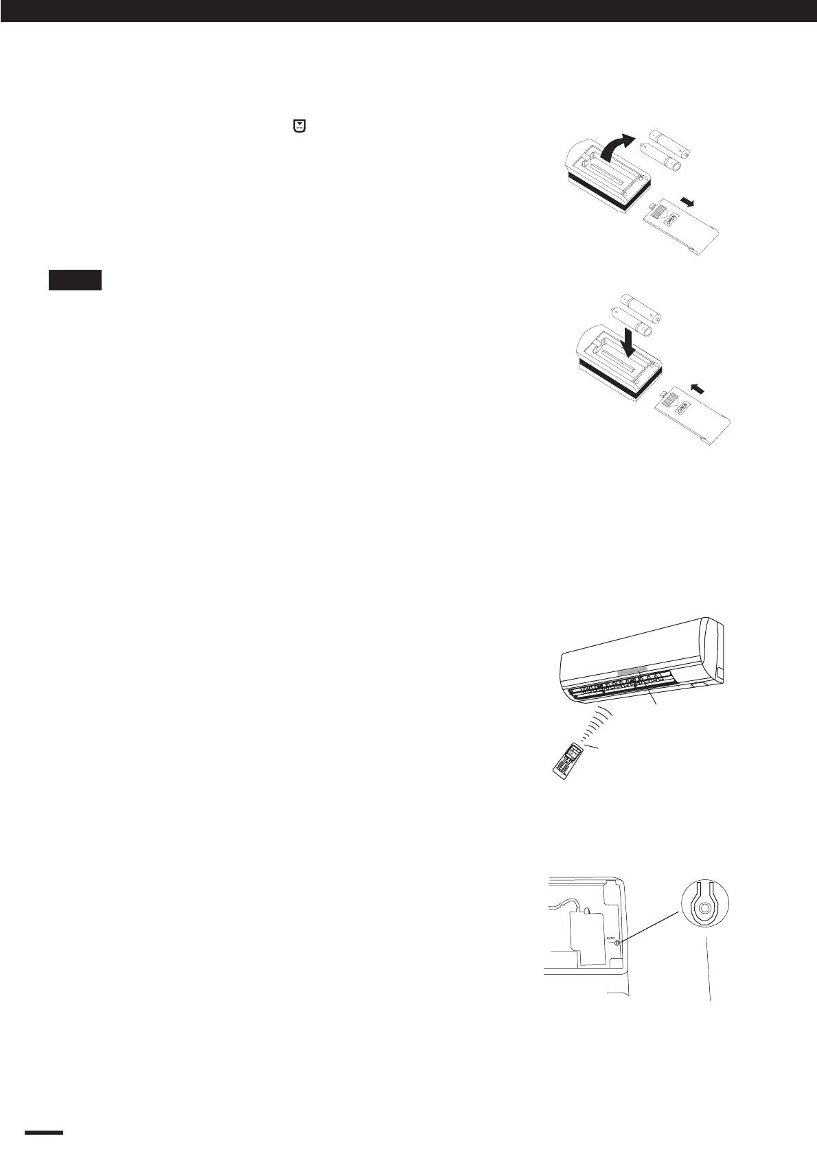
When using the remote control unit, always point the
unit’s transmitter head directly at the air conditioner’s
receiver.
(Indoor unit)
Air conditioner
Remote control unit
Fig. 3
1. Slightly to press the place with , along the
arrowhead direction to push the back cover of
wireless remote control. (Fig. 1)
2. Take out the old batteries. (Fig. 1)
3. Insert two new AAA1.5V dry batteries, and pay
attention to the polarity. (Fig. 2)
4. Attach the back cover. (Fig. 2, procedure 4)
4.7 How to Install Batteries
If the wireless remote control is lost or broken, please
use the manual switch button. At this time, the unit
will run at the “AUTO” mode, but the temperature and
fan speed cannot be changed.
To open the panel, the manual switch is located on
the displayer box. The operation was shown as below:
Turn ON the Unit: At unit turned off, press the
button, the unit will run at Auto mode immediately.
The microcomputer will accord to the indoor
temperature to select (Cooling, Heating or Fan) and
obtain the comfortable effect.
Turn OFF the Unit: At unit turned on, press the
button, the unit will stop working.
Manual switch
Fig. 4
Fig. 1
1
2
Fig. 2
Sketch map for
changing batteries
3
4
• The batteries last about six months, depending on
how much you use the remote control unit.
Replace the batteries when the remote control
unit’s display fails to light, or when the remote
control cannot be used to change the air
conditioner’s settings.
• When changing the batteries, do not use the old
or different batteries, Use two fresh leak-proof type
-AAA alkaline batteries, otherwise, it can cause the
malfunction of the wireless remote control.
• If the wireless remote control will not be used for
more than one month, please take them out, and
don't let the leakage liquid damage the wireless
remote control.
• It should be placed at where is 1m away from the
TV set or stereo sound sets. If the wireless remote
control can not operate normally, please take
them out, after 30s later and reinsert, if they can’t
normally run, please change them.
• The remote control signal can be received at a
distance of up to about 4meter.
NOTE
4.9 Emergency Operation (Fig. 4)
4.8 Using the Remote Control Unit (Fig. 3)
(Transmitter head)
Receiver
FAN
OPER
SWING
AM
C
ON
O
N
/O
FF
F
A
N
TE
M
P
-
TE
M
P
+
MO
D
E
T
IME
-
CAN
CE
L
TIME
+
S
W
I
N
G
S
L
EE
P
T
-
O
N
T
-
O
F
F
C
L
O
CK
o
4. OPERATION OF WIRELESS REMOTE CONTROL UNIT
Operation and Maintenance
16
1. For safety, be sure to turn the air conditioner off
and also disconnect the power before cleaning.
Or it may cause electric shock.
2. Never sprinkle water on the indoor unit and the
outdoor unit for cleaning because it can cause an
electric shock.
3. Volatile liquid (e.g. thinner or gasoline) will
damage the air conditioner. (So wipe the units
with a dry soft cloth, or a cloth slightly moistened
with water or cleanser.)
CAUTION
Fig. 5
Fig. 6a
Fig. 6b
Fig. 4a
Fig. 4b
1. Take off the front panel
Push in both ends of grooves to the shown position
beside at the same time by the arrow direction.
(Fig. 4a, 4b)
3. Put on front panel
Insert the supports on both ends of panel into groove,
and put the mid rotating shaft in groove, cover the
panel cover according to arrow direction and cover
well. (Fig. 6a,6b)
5.1 Clean the Front Panel
(Make sure to take It off before cleaning)
2. Washing
Clean with a soft brush, water and neutral detergent,
and then to dry it with a clean soft cloth. (Fig. 5)
Do not use hot water which temperature
above 45°C to prevent fade or
deformation.
NOTE
5.2 Cleaning the Air Filters
(Recommended once every 3 months)
1. There are microcomputer components
and circuit diagram on the LCD of front
panel.
2. After taking off the filter, some metal
edges and the fins are sharp and may
cause injury if handled improperly; be
especially careful when you clean these
parts.
3. If dust is much more around the air
conditioner, the air filters should be
cleaned more often.
4. The internal coil and other components
of the outdoor unit must be cleaned
every year. Consult your dealer or
service center.
NOTE
5. CLEAN AND CARE
Operation and Maintenance
17
.
5.4 Maintain After Use
1. Turn main power off.
2. Clean the filter, indoor and outdoor units' bodies.
3. Clear dust and obstructions from the outdoor unit.
4. Repaint the rubiginous place on the outdoor unit to
prevent it from spreading.
1. Be sure that nothing obstructs the air outlet and
intake vents. (Fig.10)
2. Check that whether ground wire is properly
connected or not.
3. Check that whether the batteries of air conditioner
are changed or not.
4. Check that whether installation stand of the outdoor
unit is damaged or not. If damaged, please contact
the dealer.
1. Take Down the Air Filters
Pull out the panel to an angle at botttom grooves on
panel. And, pull the air filter upward then downward
to take it off. (Fig. 7).
2. Cleaning
To clean the dust adhering to the filters, you can
either use a vacuum cleaner, or wash them with
warm water (the water with the neutral detergent
should below 45 C) when the filters are very dirty
(such asoil stain), and dry it in the shade. (Fig.8a)
5.2 Cleaning the Air Filters (Continued)
3. Put On Silver Ion Filters (*SAP-K18AMS only)
Put on silver Ion filters, make the side of filter with
net facing you, then cover the surface panel well.
(Fig. 9)
5.3 Check Before You Use
Fig.8a
Fig.10
Fig.7
air filter
Fig.8b
1. In general, the silver Ion filters
should be replaced once every
three months.
2. Dirty silver Ion filters can not be
washed and reused. Purchase a
replacement filter at your local
dealer. (Fig. 8b)
* Silver Ion
filter
Back side
air filter
Fig.9
o
NOTE
Don't use hot water which temperature
is above 45°C to prevent fade or
deformation.
Don't dry it on fire for filter, it would
catch a fire or deformation.
NOTE
5. CLEAN AND CARE
Operation and Maintenance
18
Don't attempt to repair the air conditioner by yourself, it can cause an electric shock or fire.
Please check the following items before asking for repair, it can save your time and money.
CAUTION
gnitoohselbuorTnonemonehP
Dot not operate immediately when the air
conditioner is restarted.
Once the air conditioner be restarted
immediately after turned off, overload
protect switch would make it will run after a 3
delay of minutes.
There's unusual smell blowing from the outlet
after operation is started.
The unit has no peculiar smell by itself. If
happened, this is the smell accumulated in the
ambient.
Solution : Clean the air filters (see Pg.16).
If the problem still has, the unit required
servicing. Hence, please contact with SANYO
authorized maintenance center.
Sound of water flow can be heard during
operation.
Sometimes there is swoosh, or gurgle while
the air conditioner is started, stopped or when
the compressor started or stopped running,
the sound is due to refrigerant flowing. They
are not malfunctions.
,rehgiheraytidimuhdna.pmetroodninehW.dettimesitsimehT
sometimes this phenomenon will happen.
This is caused by the room air is swiftly cooled
down. After run for a while, indoor temp. and
humidity will fall down, the mist will die away.
Creaking noise can be heard when start or
stop the unit.
This is caused by the deformation of plastic
due to the change of temperature.
Waiting
6. TROUBLESHOOTING
Operation and Maintenance
1 / 1

Ask a question and I''ll find the answer in the document

Finding information in a document is now easier with AI

Ask the document