Kenwood KRF-X9995D User manual
- Category
- AV receivers
- Type
- User manual

i
B60-4885-10 02 CH (M, T, X) 0011
KRF-X9995D
OC

ii
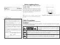
Before Applying Power
Read this section carefully to ensure safe operation.
THE LIGHTNING FLASH WITH ARROWHEAD SYMBOL, WITHIN AN EQUILATERAL TRIANGLE,
IS INTENDED TO ALERT THE USER TO THE PRESENCE OF UNINSULATED “DANGEROUS
VOLTAGE” WITHIN THE PRODUCT’S ENCLOSURE THAT MAY BE OF SUFFICIENT MAGNI-
TUDE TO CONSTITUTE A RISK OF ELECTRIC SHOCK TO PERSONS.
CAUTION: TO REDUCE THE RISK OF ELECTRIC SHOCK, DO
NOT REMOVE COVER (OR BACK). NO USER-SERVICEABLE
PARTS INSIDE. REFER SERVICING TO QUALIFIED SERVICE
PERSONNEL.
THE EXCLAMATION POINT WITHIN AN EQUILATERAL TRIANGLE IS INTENDED TO ALERT
THE USER TO THE PRESENCE OF IMPORTANT OPERATING AND MAINTENANCE (SERVIC-
ING) INSTRUCTIONS IN THE LITERATURE ACCOMPANYING THE APPLIANCE.
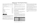
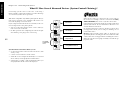
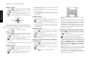
KRF-X9995D is designed for operation as follows.
U.K. and Europe ................................... AC 230 V only
Australia ................................................ AC 240 V only
*Other countries
................................ AC 110-120/220-240 V switchable
For United Kingdom
*For other countries
AC voltage selection
Note:
Our warranty does not cover damage caused by excessive
line voltage due to improper setting of the AC voltage selec-
tor switch.
AC voltage selector switch
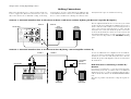
Move switch lever to match your line voltage with a small
screwdriver or other pointed tool.
The AC voltage selector switch on the rear panel is set to the
voltage that prevails in the area to which the unit is shipped.
Before connecting the power cord to your AC outlet, make
sure that the setting position of this switch matches your
line voltage. If not, it must be set to your voltage in accor-
dance with the following direction.
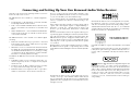
Factory fitted moulded mains plug
1. The mains plug contains a fuse. For replacement, use
only a 13-Amp ASTA-approved (BS1362) fuse.
2. The fuse cover must be refitted when replacing the
fuse in the moulded plug.
3. Do not cut off the mains plug from this equipment.
If the plug fitted is not suitable for the power points
in your home or the cable is too short to reach a
power point, then obtain an appropriate safety ap-
proved extension lead or adapter, or consult your
dealer.
If nonetheless the mains plug is cut off, remove the
fuse and dispose of the plug immediately, to avoid a
possible shock hazard by inadvertent connection to
the mains supply.
IMPORTANT : The wires in the mains lead are coloured
in accordance with the following code:
Blue : Neutral
Brown : Live
Do not connect those leads to the earth terminal of a
three-pin plug.
WARNING :
TO PREVENT FIRE OR ELECTRIC SHOCK, DO NOT EXPOSE THIS APPLIANCE
TO RAIN OR MOISTURE.
Safety Precautions
Read this section carefully to ensure safe operation.
AC 110–120V/220–240V
50/60Hz SWITCHED
TOTAL 90W MAX.
AC 220 –
240V
AC 110 –
120V

iii
Welcome to the Connection and Setup Guide for your new
Kenwood audio-video receiver.
The KRF-X9995D offers 3 kinds of 5.1-channel digital de-
coding:
• Dolby Digital, for the hundreds of currently available
Dolby Digital DVDs and LaserDiscs.
• DTS, a well-established multichannel format in movie
theaters, is available for home theater on LaserDisc and
DVD.
• MPEG Multichannel, a well-established multichannel
format in movie theaters, is available for home theater
on LaserDisc and DVD.
The KRF-X9995D also offers 2 kinds of 6.1-channel digital
decoding:
• THX Surround EX technology reproduces a surround
back channel from software which has been specially
encoded with Surround EX.
• DTS-ES also creates a 6.1-channel surround environment
by adding the surround back signals. The KRF-X9995D
can handle both DTS-ES Discrete 6.1 featuring recording
of all channels in the digital discrete format and DTS-
ES Matrix 6.1 featuring matrix encoding.
In addition, the KRF-X9995D offers the following surround
features.
• DTS-NEO:6: This converts 2-channel signals into 6.1-
channel signals by means of a high-accuracy digital
matrix decoder.
• Dolby Pro Logic II: This is advanced version of Dolby
Pro Logic and features improved audio quality.
• THX Ultra: This corrects signals in order to reproduce a
similar acoustic field to movie theaters in home use.
Connecting and Setting Up Your New Kenwood Audio-Video Receiver
D.R.I.V.E. circuit: This is a Kenwood original technology for
reproducing signals with high resolution by instant switch-
ing of the internal filters according to the input signal. The
KRF-X9995D incorporate a high performance DSP to pro-
vide very high resolution from a 32-bit DRIVE III circuit,
achieving stereo audio reproduction with the best quality
ever reached.
HDCD®: This is a new format of high-resolution recording.
The KRF-X9995D is capable of reproducing CDs recorded
in the HDCD format with high resolution and wide dynamic
range.
Use it to connect all your current audio and video com-
ponents—the KRF-X9995D has a variety of connection jacks
so you can customize your entertainment setup.
It also includes Kenwood’s remarkable PowerTouch LCD
remote—a graphical user interface without having to use
your TV!
Other advanced features include 6 S-Video inputs and an
optical and coaxial digital outputs for digital dubbing to
MiniDisc or CD-R. For a match made in “dual-room
heaven,” get the DPF-J9030, DPF-J9020 or DPF-J9010
changer.
Manufactured under license from Digital Theater Systems,
Inc. US Pat. No. 5,451,942, 5,956,674, 5,974,380, 5,978,762
and other world-wide patents issued and pending. “DTS”,
“DTS-ES Extended Surround” and “Neo:6” are trademarks
of Digital Theater Systems, Inc.Copyright 1996, 2000 Digi-
tal Theater Systems, Inc. All Rights Reserved.
Manufactured under license from Dolby Laboratories.
"Dolby", "Pro Logic", "Surround EX " and the double-D sym-
bol are trademarks of Dolby Laboratories. Confidential un-
published works. Copyright 1992-1997 Dolby Laboratories.
All rights reserved.
, HDCD®, High Definition Compatible Digital® and
Pacific Microsonics
TM
are either registered trademarks or
trademarks of Pacific Microsonics, Inc. in the United States
and/or other countries. HDCD system manufactured under
license from Pacific Microsonics, Inc. This product is cov-
ered by one or more of the following: IN the USA: 5,479,168,
5,638,074, 5,640,161, 5,808,574, 5,838,274, 5,854,600,
5,864,311, 5,872,531, and in Australia: 669114. Other pat-
ents pending.
Lucasfilm and THX are registered trademarks of Lucasfilm
Ltd.
©Lucasfilm Ltd. & TM. All rights reserved. Surround EX is a
jointly developed technology of THX and Dolby Laborato-
ries Inc. and is a trademark of Dolby. Used under authori-
zation.

iv
The above are additional trademarked names appearing in
this manual. All other products named are trademarks of
their respective companies.
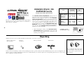
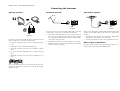
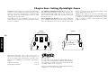
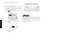
Unpacking
If any accessories are missing, or if the receiver is damaged or fails to operate, notify your dealer immediately. If your receiver was shipped to you
directly, notify your shipper immediately. Kenwood recommends that you retain the original carton and packing materials in case you need to
move or ship the receiver in the future.
Unpack your new receiver carefully and make sure that all the accessories are present:
ENTER
V
O
L
U
M
E
UP
DOWN
CONFIRM
ON/STANDBYCONTRAST REMOTE OFF
Remote control unit
(PowerTouch)
Batteries
AA (R6) × 6
AM Loop Antenna
AC plug adapter
FM Antenna
Use to adapt the plug on the power
cord to the shape of the wall outlet.
(Present only for regions where use
is necessary.)
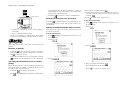
CHANNEL SPACE / DE-
EMPHASIS Switch
Not present for U.K. and Australia
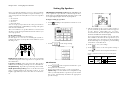
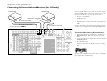
The CHANNEL SPACE/ DE-EMPHASIS switch on the rear
panel is set to the correct setting that prevails in the area to
which the unit is shipped. However, if the CHANNEL
SPACE/ DE-EMPHASIS setting is not matched to the area
where the unit is to be used; for instance, if you move from
area 1 to area 2 as shown in the table to the right or vice
versa, desired reception of AM/ FM broadcasts is not ex-
pected. In this case, change the CHANNEL SPACE/ DE-
EMPHASIS setting in accordance with the area correspond-
ing to the table. The CHANNEL SPACE/ DE-EMPHASIS is
switched over at the same time.
• When changing the setting of the CHANNEL SPACE/
DE-EMPHASIS switch, first unplug the power cord, and
then reset the switch, plug the power cord back in, and
turn the power switch on.
CHANNEL SPACE
DE-EMPHASIS switch
Area
CHANNEL
SPACE freq.
DE-
EMPHASIS
USA, Canada,
and South
American
Countries
Other
Countries
1
2
FM : 100 kHz
AM : 10 kHz
FM : 50 kHz
AM : 9 kHz
75 µs
50 µs
ANTENNA
GND
AM
50 µs
AM 9kHz
FM 50kHz
75 µs
AM 10kHz
FM 100kHz
DE-EMPHASIS
CHANNEL SPACE

v
Table of Contents
Chapter One: Connecting Your Devices .... 1
Noting Your Devices .............................................. 3
Connecting Your Speakers .................................... 4
To Connect Front Speakers Only
To Connect Front and Surround Sound
Speakers
What if I Have a Powered Subwoofer?
To Connect Surround Back Speaker
What if I Have an Amplifier? ................................. 8
Connecting Your TV ............................................ 10
To Connect a TV
What if I Want to Watch TV without Turning
on the Receiver?
Connecting Your Cable TV or Satellite Tuner ..... 12
To Connect a Cable TV Tuner with a
Composite (RCA) Video Output
To Connect a Cable TV Tuner without a
Composite (RCA) Video Output
To Connect a Satellite Tuner
Connecting Your VCR(s) ..................................... 14
To Connect a Primary VCR
To Connect a Secondary VCR
Connecting Your Primary CD Player .................. 16
What if I Have a Video CD-Compatible CD
Player?
To Connect a Kenwood 200-Disc CD
Changer
To Connect Any Other Primary CD Player or
Changer
To Connect a Secondary CD Player
Connecting Your DVD Player .............................. 18
To Connect a DVD Player
Connecting Your CD-R Recorder ........................ 20
To Connect a CD-R Recorder
Connecting Your MD Recorder or Primary
Tape Deck ......................................................... 22
To Connect an MD Recorder
To Connect a Primary Tape Deck
To Connect a Secondary Tape Deck
Connecting Your Secondary CD Player or
Tape Deck ......................................................... 24
To Connect a Secondary CD Player
To Connect a Secondary Tape Deck
Connecting Your Laser Disc Player
(with AC-3 RF Output) ..................................... 26
To Connect an AC-3 RF Output Laser Disc
Player
Connecting Your Laser Disc Player
(without AC-3 RF Output) ............................... 28
To Connect a PCM Digital Output Laser Disc
Player
Connecting Your Turntable/Record Player ......... 30
To Connect a Turntable/Record Player
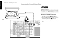
Connecting a Camcorder or Additional VCR ..... 31
To Connect a Camcorder or Additional VCR
Can I Connect an Additional VCR Perma-
nently?
What if I Have Several Kenwood Devices (System
Control Chaining)? .......................................... 32
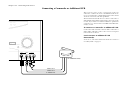
Connecting the Antennas .................................... 33
AM Loop Antenna
FM Indoor Antenna
FM Outdoor Antenna
What if I Have Cable Radio?
Chapter Two: Setting Up PowerTouch ... 34
Installing the Batteries ........................................ 34
Calibrating the Touch Screen .............................. 35
Resetting PowerTouch
Selecting the Model Type .................................... 35
Navigating PowerTouch Interface ....................... 36

Table of Contents
vi
Setting Up Speakers ............................................ 37
Speaker Placement
SP Selection
SP Distance
SP Level
Bass Peak Level
Identifying Devices For PowerTouch Control ..... 40
How Do I Identify Devices?
How Do I Replace a Setup Code with a New
One?
How Do I Delete Setup Codes?
Example of device button display
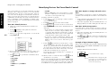
Storing Radio Stations in Memory (optional) ... 41
Storing RDS Stations Automatically
(for U.K.only)
Storing RDS Stations Name (PS Read)
(for U.K.only)
Storing Stations Manually
To Customize the PowerTouch Screen ................ 43
Changing the Name
Changing the Item Size
Moving an Item
Cutting an Item
Copying an Item
Pasting an Item
Deleting an Item
Selecting an Item in the Gallery and Pasting
it in the Screen
Programming a Function in a Button (Learn)
Resetting to Default
Switching the Customized Screen to another
(Jump)
To Undo the Last Operation Performed
Locking Customization Results with a
Password
Chapter Three: Setting Up on the Receiver
............................................................. 46
Speaker Setup
Storing Radio Stations in Memory (op-
tional)
Chapter Four: Setting Up Multiple Zones
............................................................. 48
Making Connections ........................................... 49
Scenario 1: Surround Sound in Zone A only/
Stereo in Zone A and Stereo in Zone B
(Using the Receiver’s Speaker B Outputs)
Scenario 2: Surround Sound in Zone A and
Stereo in Zone B (Using a Stereo Amplifier
in Zone B)
Both Scenarios: Connecting a Second TV/
Monitor
Setting Up the PowerTouch ................................. 50
Connecting the External Infrared Receivers (for
U.K.only) .......................................................... 51
To Connect IR Receivers (IR Transceivers)
Connecting and Setting Up On/Off Sensors or
Relay Controls (for U.K.only) .......................... 52
To Connect Relay Controls
To Connect TV ON/OFF Sensors
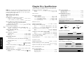
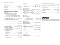
Chapter Five: Specifications .................. 55
KRF-X9995D (for U.K.)
KRF-X9995D (for Other Countries)

1
Chapter One : Connecting Your Devices
Connections
Chapter One: Connecting Your Devices
Welcome to the Kenwood KRF-X9995D Connection and
Setup Guide. This chapter guides you through connecting
your home entertainment devices to your new Kenwood
audio-video receiver.
Once all your devices are connected, you can set up the
PowerTouch (see Chapter Two).
Refer to the following pages for details on connecting these
devices:
Speakers page 4
TV page 10
VCR(s) page 14
CD Player, Kenwood 200-Disc Changer page 16
DVD Player page 18
CD-R Recorder page 20
MD Recorder page 22
Tape Deck(s) page 22
Laser Disc Player page 26
Turntable page 30
Camcorder/Second VCR page 31
Antennas page 33
All necessary cables should be provided with your home
entertainment device (not with your new receiver). If you
do not have the correct cables, you may purchase these
cables from any home entertainment store.
To make coaxial digital connections, be sure to use a high-
quality digital audio cable, not a standard audio cable.
Do not plug in the receiver or any other device to AC power
until all connections have been made. Once all devices have
been connected, you may plug them in and provide power.
Important:
Be sure to adhere followings, or proper ventilation will be
blocked causing damage or fire hazard.
Do not place any objects impairing heat radiation onto the
top of unit.
Leave a space around the unit (from the largest outside di-
mension including projection) equal or greater than, shown
below.
Top panel : 50 cm Side panel : 10 cm Back panel : 10 cm
Do not install your receiver where direct sunlight or high fre-
quency fluorescent lighting can shine directly into the remote
sensor. This can cause your new receiver to malfunction.
Before You Begin
This manual covers the most common and standard con-
nections to the receiver. Because of its versatility, you may
decide to connect your devices differently.
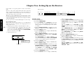
Video Connections
This receiver incorporates Kenwood's exclusive Universal
Video HD, which converts between composite, S-Video and
component video formats. This simplifies operation, and
maintains the highest possible video quality while requir-
ing only a single connection between the receiver and your
TV. Video format conversion is performed according to the
following chart:
If several video connections are made, one of them will be
selected based on the priority 3, 2, and 1.
• Component video connections provide the best video
quality; S-Video connections provide video quality that
is superior to standard composite video connections.
We recommend using the highest quality connection
possible between the receiver and your TV.
• Since component video inputs are not downconverted
to S-Video or composite video, if you want to record
components connected via component video inputs you
must also connect that component's S-Video or com-
posite video outputs to the receiver.
• If you plan on using the KRF-X9995D in a Dual-Zone
application (see Chapter Four), you must use the com-
posite video connections in addition to any component
video and S-Video connections for all source compo-
nents. Only video sources connected to the receiver with
composite video connections can be viewed in the sec-
ond zone.
Video input signal type Appears at these video outputs
1 Composite Video Composite
S-Video
Component Video
2 S-Video Composite
S-Video
Component Video
3 Component Video Component Video

2
Chapter One : Connecting Your Devices
Connections
OPTICAL
VIDEO
4
VIDEO
3
VIDEO
2
CD-R
MD/
TAPE1
CD1
DVD
EXT.CONTROL
RS-232C
DIGITAL IN
COAXIAL
DIGITAL OUT
VIDEO
3 IN
COMPONENT VIDEO
DVD
IN
MONITOR
OUT
MONITOR
OUT
PLAY
IN
PLAY
IN
PLAY
IN
PLAY
IN
REC
OUT
REC
OUT
PLAY
IN
S VIDEO VIDEO
PRE OUTZONE B PRE OUT
R L
AUDIO
R L
FRONT
R L
SURROUND
R LR L
SURROUND BACK
SUB WOOFER
CENTER
VIDEO
R L
B
A
AUDIO
VIDEO1
VIDEO2
VIDEO3
VIDEO4
DVD
FRONT
DVD/
6CH.
INPUT
SURROUND
CENTER
SUBWOOFER
PHONO
CD1
REC
OUT
PLAY
IN
MD/
TAPE1
REC
OUT
PLAY
IN
CD-R
REC
OUT
PLAY
IN
CD2/
TAPE2
MONITOR
CENTER
SPEAKER
(6–16Ω)
SURROUND
SPEAKERS
(6–16Ω)
AC 120V 60Hz
SWITCHED TOTAL
90W 0.75A MAX.
FRONT SPEAKERS
(6–16Ω)
ANTENNA
GND
AM
FM 75Ω
SYSTEM
CONTROL
SL16 TEXT
REMOTE
TV ON/OFF
SENSOR
RELAY
CONTROL
IR OUT
LCD
REMOTE
IR RECEIVER
IN
IR RECEIVER
IN
DVD CONTROL
C
R
L
R
L
A B
DC5V 10mA
DC12V 20mA
DC12V
20mA
DC12V 20mA
AC 220 –
240V
AC 110 –
120V
50 µs
AM 9kHz
FM 50kHz
75 µs
AM 10kHz
FM 100kHz
DE-EMPHASIS
CHANNEL SPACE
P
R
/C
R
P
B
/C
B
Y
P
R
/C
R
P
B
/C
B
Y
P
R
/C
R
P
B
/C
B
Y
IR OUT
LCD
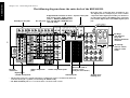
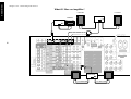
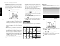
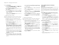
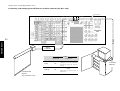
AC Plugs
AC voltage
selector switch
(only for some
areas)
Speaker wire
binding post
Zone B pre out jacks
Video component
jacks
Audio component jacks
Pre out jacks
Antenna jacks
Supplemental infrared receiver
and sensor jacks, DVD control
jacks**, RELAY CONTROL jack
and TV ON/OFF SENSOR jack
(for U.K. only)
The shape of
plugs are
different between
countries
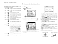
Note that some component jacks are linked to spe-
cific digital jacks. For example, if you connect a video
component with a digital optical cable, you should con-
nect the analog cables to the VIDEO2 video component
jacks and the digital cable to the VIDEO2 digital optical
jack.
System control jacks
The following diagram shows the entire back of the KRF-X9995D.
Channel space/FM de-
emphasis
switch
(only for some areas)
RS-232C
connector*
Digital jacks
(coaxial and optical)
* The RS-232C connector is provided for future capability (to connect a commercially marketed
controller having the capability of controlling the KRF-X9995D).
** The DVD CONTROL jacks are reserved for future extension of the system.

3
Chapter One : Connecting Your Devices
Connections
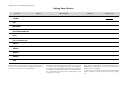
Noting Your Devices
Use this table and the diagram on the preceding page to
plan your connections before you make them, or use it to
record your connections as you make them.
You will need this information later, when you set up your
PowerTouch (see “Identifying Devices For PowerTouch Con-
trol” on page 40). Recording this information now will save
you additional trips behind your home entertainment cabi-
net. You will fill in the Setup Code column when you are
setting up PowerTouch.
Jack Set Device Manufacturer Model # Setup Code
PHONO
CD1
MD/TAPE1
CD2/TAPE2 MONITOR
CD-R
VIDEO1
VIDEO2
VIDEO3
VIDEO4
DVD
MONITOR OUT
(TV on PowerTouch)
When playing Dolby Digital
*
or DTS-encoded software in
multichannel configuration, the connected audio signal
should be the digital signal.
*
When playing a LaserDisc recorded in the Dolby Digital
format, connect the AC-3 RF output to the receiver (See page
26).

4
Chapter One : Connecting Your Devices
Connections
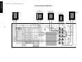
Connecting Your Speakers
OPTICAL
VIDEO
4
VIDEO
3
VIDEO
2
CD-R
MD/
TAPE1
CD1
DVD
EXT.CONTROL
RS-232C
DIGITAL IN
COAXIAL
DIGITAL OUT
VIDEO
3 IN
COMPONENT VIDEO
DVD
IN
MONITOR
OUT
MONITOR
OUT
PLAY
IN
PLAY
IN
PLAY
IN
PLAY
IN
REC
OUT
REC
OUT
PLAY
IN
S VIDEO VIDEO
PRE OUTZONE B PRE OUT
R L
AUDIO
R L
FRONT
R L
SURROUND
R LR L
SURROUND BACK
SUB WOOFER
CENTER
VIDEO
R L
B
A
AUDIO
VIDEO1
VIDEO2
VIDEO3
VIDEO4
DVD
FRONT
DVD/
6CH
INPUT
SURROUND
CENTER
SUBWOOFER
PHONO
CD1
REC
OUT
PLAY
IN
MD/
TAPE1
REC
OUT
PLAY
IN
CD-R
REC
OUT
PLAY
IN
CD2/
TAPE2
MONITOR
CENTER
SPEAKER
(6–16Ω)
SURROUND
SPEAKERS
(6–16Ω)
AC 120V 60Hz
SWITCHED TOTAL
90W 0.75A MAX.
FRONT SPEAKERS
(6–16Ω)
ANTENNA
GND
AM
FM 75Ω
SYSTEM
CONTROL
SL16 TEXT
REMOTE
TV ON/OFF
SENSOR
RELAY
CONTROL
IR OUT
LCD
IR OUT LCD
REMOTE
IR RECEIVER
IN
IR RECEIVER
IN
DVD CONTROL
C
R
L
R
L
A B
DC5V 10mADC12V 20mA
DC12V
20mA
DC12V 20mA
AC 220 –
240V
AC 110 –
120V
50 µs
AM 9kHz
FM 50kHz
75 µs
AM 10kHz
FM 100kHz
DE-EMPHASIS
CHANNEL SPACE
PR/CR
PB/CB
Y
PR/CR
PB/CB
Y
PR/CR
PB/CB
Y
R
FRONT
L
FRONT
R
SURROUND
L
SURROUND
CENTER

5
Chapter One : Connecting Your Devices
Connections
Connecting Your Speakers, continued
Do not plug in the receiver to AC power until all connec-
tions have been made.
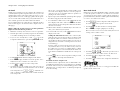
To Connect Front Speakers Only:
If you only intend to listen to stereo sound (as opposed to
surround sound), you may simply connect a single pair of
speakers. To do so:
Using Banana Plugs (except for U.K.):
1. Tighten the speaker wire binding posts. If you do not
tighten the posts, they will not conduct sound properly
to the speakers.
2. Insert the plug from the positive jack on the RIGHT
FRONT speaker into the pin jack on the positive RIGHT
FRONT post. Repeat for the negative plug.
3. Repeat step 2 for the positive and negative wires on the
LEFT FRONT speaker.
Using Bare Wires:
1. Loosen the speaker wire binding posts.
2. Insert the wire from the positive jack on the RIGHT
FRONT speaker into the U-shaped slot in the base of
the positive RIGHT FRONT post. Lay the wire to the
right of the post; that way, when you tighten the bind-
ing post, it will naturally twist the wire into the best
connection. Tighten the post. Repeat for the negative wire
on the RIGHT FRONT speaker as shown to the right.
3. Repeat step 2 for the positive and negative wires on the
LEFT FRONT speaker.
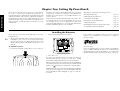
To Connect Front and Surround Sound
Speakers:
To listen to the full surround sound that this receiver can
put out, connect front speakers, center, left surround, and
right surround speakers. To do so:
To reproduce more enriched bass, connect a subwoofer
incorporating a power amplifier.
For the connections of the subwoofer and surround back
speakers, see page 6 to 7.
Using Banana Plugs (except for U.K.):
1. Tighten the speaker wire binding posts. If you do not
tighten the posts, they will not conduct sound properly
to the speakers.
2. Follow the steps under “To Connect Front Speakers
Only” on this page to connect the RIGHT and LEFT
FRONT speakers.
3. Insert the plug from the positive jack on the CENTER
speaker into the pin jack on the positive CENTER post.
Repeat for the negative plug.
4. Insert the plug from the positive jack on the RIGHT
SURROUND speaker into the pin jack on the positive
RIGHT SURROUND post. Repeat for the negative plug.
5. Repeat step 4 for the positive and negative wires on the
LEFT SURROUND speaker.
Using Bare Wires:
1. Loosen the speaker wire binding posts.
2. Follow the steps under “To Connect Front Speakers
Only” on this page to connect the RIGHT and LEFT
FRONT speakers.
3. Insert the wire from the positive jack on the CENTER
speaker into the U-shaped slot in the base of the positive
CENTER post as shown to the right.
Tighten the post. Repeat for the negative wire.
4. Insert the wire from the positive jack on the RIGHT SUR-
ROUND speaker into the U-shaped slot on the base of
the positive RIGHT SURROUND post. Tighten the post.
Repeat for the negative wire.
5. Repeat step 4 for the positive and negative wires on the
LEFT SURROUND speaker.
Never short circuit the + and - speaker wires.
Do not switch the left and right speaker wires or swap the +
and - wires on the binding posts.
The speakers must have a nominal impedance of between
6Ω and 16Ω.
Using Bare Wires
1. Loosen post
2. Insert wire
3. Tighten post

6
Chapter One : Connecting Your Devices
Connections
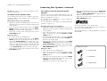
Connecting Your Speakers, continued
REMOTE
IR OUT
LCD
OPTICAL
VIDEO
4
VIDEO
3
VIDEO
2
CD-R
MD/
TAPE1
CD1
DVD
EXT.CONTROL
RS-232C
DIGITAL IN
COAXIAL
DIGITAL OUT
VIDEO
3 IN
COMPONENT VIDEO
DVD
IN
MONITOR
OUT
MONITOR
OUT
PLAY
IN
PLAY
IN
PLAY
IN
PLAY
IN
REC
OUT
REC
OUT
PLAY
IN
S VIDEO VIDEO
PRE OUTZONE B PRE OUT
R L
AUDIO
R L
FRONT
R L
SURROUND
R LR L
SURROUND BACK
SUB WOOFER
CENTER
VIDEO
R L
B
A
AUDIO
VIDEO1
VIDEO2
VIDEO3
VIDEO4
DVD
FRONT
DVD/
6CH
INPUT
SURROUND
CENTER
SUBWOOFER
PHONO
CD1
REC
OUT
PLAY
IN
MD/
TAPE1
REC
OUT
PLAY
IN
CD-R
REC
OUT
PLAY
IN
CD2/
TAPE2
MONITOR
CENTER
SPEAKER
(6–16Ω)
SURROUND
SPEAKERS
(6–16Ω)
AC 120V 60Hz
SWITCHED TOTAL
90W 0.75A MAX.
FRONT SPEAKERS
(6–16Ω)
ANTENNA
GND
AM
FM 75Ω
SYSTEM
CONTROL
SL16 TEXT
REMOTE
TV ON/OFF
SENSOR
RELAY
CONTROL
IR OUT
LCD
IR RECEIVER
IN
IR RECEIVER
IN
DVD CONTROL
C
R
L
R
L
A B
DC12V 20mADC12V 20mA
DC12V
20mA
DC12V 20mA
AC 220 –
240V
AC 110 –
120V
DE-EMPHASIS
CHANNEL SPACE
P
R
/C
R
P
B
/C
B
Y
P
R
/C
R
P
B
/C
B
Y
P
R
/C
R
P
B
/C
B
Y
50 µs
AM 9kHz
FM 50kHz
75 µs
AM 10kHz
FM 100kHz
R
SURROUND
BACK
L
SURROUND
BACK
Power Amp.
POWERED
SUBWOOFER

7
Chapter One : Connecting Your Devices
Connections
Connecting Your Speakers, continued
Do not plug in the amplifiers or the receiver to AC power
until all connections have been made.
What if I Have a Powered Subwoofer?
Simply connect the subwoofer’s audio cable to the receiver’s
SUBWOOFER PRE OUT jack as shown to the left.
To Connect Surround Back Speakers:
To reproduce the surround back channels by Dolby Digital
Surround EX, DTS-ES or DTS-NEO:6, add a commercially
marketed 2-channel power amplifier and connect the
surround back speakers to it.
To connect supplemental power amplifiers and surround
back speakers:
1. Using RCA audio cables (not supplied), connect the
receiver’s SURROUND BACK PRE OUT jacks to the
amplifiers’ input jacks as shown to the left.
2. Connect the speakers to the power amplifiers according
to the amplifiers’ instruction manuals.

8
Chapter One : Connecting Your Devices
Connections
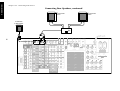
What if I Have an Amplifier?
OPTICAL
VIDEO
4
VIDEO
3
VIDEO
2
CD-R
MD/
TAPE1
CD1
DVD
EXT.CONTROL
RS-232C
DIGITAL IN
COAXIAL
DIGITAL OUT
VIDEO
3 IN
COMPONENT VIDEO
DVD
IN
MONITOR
OUT
MONITOR
OUT
PLAY
IN
PLAY
IN
PLAY
IN
PLAY
IN
REC
OUT
REC
OUT
PLAY
IN
S VIDEO VIDEO
PRE OUTZONE B PRE OUT
R L
AUDIO
R L
FRONT
R L
SURROUND
R LR L
SURROUND BACK
SUB WOOFER
CENTER
VIDEO
R L
B
A
AUDIO
VIDEO1
VIDEO2
VIDEO3
VIDEO4
DVD
FRONT
DVD/
6CH
INPUT
SURROUND
CENTER
SUBWOOFER
PHONO
CD1
REC
OUT
PLAY
IN
MD/
TAPE1
REC
OUT
PLAY
IN
CD-R
REC
OUT
PLAY
IN
CD2/
TAPE2
MONITOR
CENTER
SPEAKER
(6–16Ω)
SURROUND
SPEAKERS
(6–16Ω)
AC 120V 60Hz
SWITCHED TOTAL
90W 0.75A MAX.
FRONT SPEAKERS
(6–16Ω)
ANTENNA
GND
AM
FM 75Ω
SYSTEM
CONTROL
SL16 TEXT
REMOTE
TV ON/OFF
SENSOR
RELAY
CONTROL
IR OUT
LCD
IR RECEIVER
IN
IR RECEIVER
IN
DVD CONTROL
C
R
L
R
L
A B
DC5V 10mADC12V 20mA
DC12V
20mA
DC12V 20mA
AC 220 –
240V
AC 110 –
120V
DE-EMPHASIS
CHANNEL SPACE
P
R
/C
R
P
B
/C
B
Y
P
R
/C
R
P
B
/C
B
Y
P
R
/C
R
P
B
/C
B
Y
50 µs
AM 9kHz
FM 50kHz
75 µs
AM 10kHz
FM 100kHz
REMOTE
IR OUT
LCD
R FRONT L FRONT
Power Amp.
R SURROUND
L SURROUND
Power Amp.
CENTER
Power Amp.

9
Chapter One : Connecting Your Devices
Connections
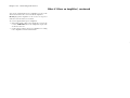
What if I Have an Amplifier?, continued
You can use supplemental power amplifiers for any of the
channels instead of the receiver’s built-in amplifiers.
Do not plug in the amplifiers or the receiver to AC power
until all connections have been made.
To connect supplemental power amplifiers:
1. Using RCA audio cables (not supplied), connect the
receiver’s PRE OUT jacks to the amplifiers’ input jacks
as shown to the left.
2. Connect the speakers to the power amplifiers according
to the amplifiers’ instruction manuals.

10
Chapter One : Connecting Your Devices
Connections
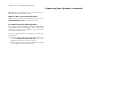
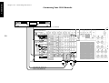
Connecting Your TV
OPTICAL
VIDEO
4
VIDEO
3
VIDEO
2
CD-R
MD/
TAPE1
CD1
DVD
EXT.CONTROL
RS-232C
DIGITAL IN
COAXIAL
DIGITAL OUT
VIDEO
3 IN
DVD
IN
MONITOR
OUT
MONITOR
OUT
PLAY
IN
PLAY
IN
PLAY
IN
PLAY
IN
REC
OUT
REC
OUT
PLAY
IN
S VIDEO VIDEO
PRE OUTZONE B PRE OUT
R L
AUDIO
R L
FRONT
R L
SURROUND
R LR L
SURROUND BACK
SUB WOOFER
CENTER
VIDEO
R L
B
A
AUDIO
VIDEO1
VIDEO2
VIDEO3
VIDEO4
DVD
FRONT
DVD/
6CH
INPUT
SURROUND
CENTER
SUBWOOFER
PHONO
CD1
REC
OUT
PLAY
IN
MD/
TAPE1
REC
OUT
PLAY
IN
CD-R
REC
OUT
PLAY
IN
CD2/
TAPE2
MONITOR
ANTENNA
GND
AM
FM 75Ω
SYSTEM
CONTROL
SL16 TEXT
REMOTE
TV ON/OFF
SENSOR
RELAY
CONTROL
IR OUT
LCD
IR RECEIVER
IN
IR RECEIVER
IN
DVD CONTROL
A
DC5V 10mADC12V 20mA
DC12V
20mA
DC12V 20mA
DE-EMPHASIS
CHANNEL SPACE
COMPONENT VIDEO
P
R
/C
R
P
B
/C
B
Y
P
R
/C
R
P
B
/C
B
Y
P
R
/C
R
P
B
/C
B
Y
50 µs
AM 9kHz
FM 50kHz
75 µs
AM 10kHz
FM 100kHz
REMOTE
IR OUT
LCD
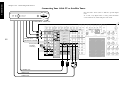
COMPOSITE VIDEO IN
COMPONENT VIDEO IN
S-VIDEO IN

11
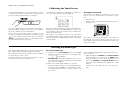
Chapter One : Connecting Your Devices
Connections
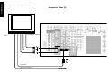
Connecting Your TV, continued
Do not plug in the receiver or devices to AC power until
you have connected all your devices.
This section focuses on the connections from your TV to
the KRF-X9995D. Please refer to your TV’s instructions for
more detail about its connection jacks and capabilities.
The instructions in this section show how to connect your
TV as a monitor for the other video devices you connect
(without using it as an audio/video source device itself). To
use your TV as an audio/video source device, you must first
connect it as described in this section, and also connect its
audio/video output jacks as if they were cable TV tuner out-
puts, as described in “To Connect a Cable TV Tuner with a
Composite (RCA) Video Output” on page 13.
To Connect a TV:
1. Review the information under “Before You Begin” on
page 1. It contains important notes about the types of
video connections you can make.
2. Connect a video cable from your TV’s Video IN jack to
the receiver’s MONITOR OUT jack as shown to the left.
3. If your TV has the COMPONENT VIDEO jacks, you can
also connect it as shown on the left.
4. If your TV does not have any video input connections,
you must purchase an RF modulator. The modulator
will convert the video signal from the receiver to an RF
signal that will work with the TV’s antenna connections.
Connect the receiver to the TV according to the RF
modulator’s instruction manual.
5. Go to “Noting Your Devices” on page 3 and note which
jack you used to connect your TV. In addition, note the
brand name and model number of the TV.
If you previously connected your TV directly to your VCR,
you must now connect it through your new receiver.
What if I Want to Watch TV without Turning
on the Receiver?
The connection described here sets your TV up as a monitor
you can use to view media played on your other video de-
vices (such as a VCR or DVD player). You can still watch TV
without having to use the receiver.
With some devices, the COMPONENT VIDEO jacks (Y, PB/
CB, PR/CR jacks) are indicated as the R-Y, B-Y jacks. For
details, refer to the operation instructions for the respective
device.

12
Chapter One : Connecting Your Devices
Connections
OPTICAL
VIDEO
4
VIDEO
3
VIDEO
2
CD-R
MD/
TAPE1
CD1
DVD
EXT.CONTROL
RS-232C
DIGITAL IN
COAXIAL
DIGITAL OUT
VIDEO
3 IN
P
R
/C
R
P
B
/C
B
Y
P
R
/C
R
P
B
/C
B
Y
P
R
/C
R
P
B
/C
B
Y
COMPONENT VIDEO
DVD
IN
MONITOR
OUT
MONITOR
OUT
PLAY
IN
PLAY
IN
PLAY
IN
REC
OUT
REC
OUT
PLAY
IN
S VIDEO VIDEO
PRE OUTZONE B PRE OUT
R L
AUDIO
R L
FRONT
R L
SURROUND
R LR L
SURROUND BACK
SUB WOOFER
CENTER
VIDEO
R L
B
A
AUDIO
VIDEO1
VIDEO2
VIDEO4
DVD
FRONT
DVD/
6CH
INPUT
SURROUND
CENTER
SUBWOOFER
PHONO
CD1
REC
OUT
PLAY
IN
MD/
TAPE1
REC
OUT
PLAY
IN
CD-R
REC
OUT
PLAY
IN
CD2/
TAPE2
MONITOR
CENTER
SPEAKER
(6–16Ω)
SURROUND
SPEAKERS
(6–16Ω)
FRONT SPEAKERS
(6–16Ω)
ANTENNA
GND
AM
FM 75Ω
SYSTEM
CONTROL
SL16 TEXT
REMOTE
TV ON/OFF
SENSOR
RELAY
CONTROL
IR OUT
LCD
IR RECEIVER
IN
IR RECEIVER
IN
DVD CONTROL
C
R
L
A
DC5V 10mADC12V 20mA
DC12V
20mA
DC12V 20mA
DE-EMPHASIS
CHANNEL SPACE
PLAY
IN
VIDEO3
50 µs
AM 9kHz
FM 50kHz
75 µs
AM 10kHz
FM 100kHz
REMOTE
IR OUT
LCD
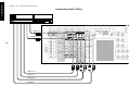
Remove protective
cap before
connecting.
AUDIO OUT
VIDEO OUT
S-VIDEO OUT
DIGITAL OUT-
OPTICAL or COAXIAL
COMPONENT VIDEO OUT
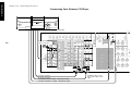
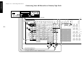
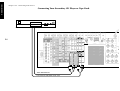
Connecting Your Cable TV or Satellite Tuner
Note that video device jacks are linked to specific digital
jacks.
As a result, every digital cable or analog cable should be
connected between jacks having the same name.

13
Chapter One : Connecting Your Devices
Connections
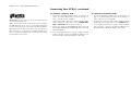
Connecting Your Cable TV or Satellite Tuner, continued
Do not plug in the receiver or devices to AC power until
you have connected all your devices.
This section focuses on the connections from your cable or
satellite tuner to the KRF-X9995D. Please refer to your
tuner’s instructions for more detail about its connection
jacks and capabilities.
The instructions in this section show one of several pos-
sible variations on connecting your tuner. For further assis-
tance on optional configurations, contact your cable or sat-
ellite provider.
To Connect a Cable TV Tuner with a
Composite (RCA) Video Output:
1. Review the information under “Before You Begin” on
page 1. It contains important notes about the types of
video connections you can make.
2. Connect the audio and video cables from the cable
tuner’s Audio and Video OUT jacks to the receiver’s
VIDEO2, VIDEO3, or VIDEO4 PLAY IN jacks as shown
to the left.
When the component video cables are connected, the
audio and video cables of the cable TV tuner should be
connected to the VIDEO3 jacks of the receiver.
3. If your cable TV tuner and TV have the COMPONENT
VIDEO jacks, you can also connect them as shown on the
left.
4. Go to “Noting Your Devices” on page 3 and note which
jack you used to connect your tuner. In addition, note
the brand name and model number of the tuner.
To Connect a Cable TV Tuner without a
Composite (RCA) Video Output:
1. Connect the audio cables from the cable tuner’s Audio
Out jacks to the receiver’s VIDEO2, VIDEO3, or VIDEO4
PLAY IN jacks as shown to the left.
2. Leave the cable tuner’s video out (RF jack) connected
directly to your VCR or TV (wherever you already have
it connected).
3. Go to “Noting Your Devices” on page 3 and note which
jack you used to connect your tuner. In addition, note
the brand name and model number of the tuner.
To Connect a Satellite Tuner:
1. Review the information under “Before You Begin” on
page 1. It contains important notes about the types of
video connections you can make.
2. If your satellite tuner has a digital output jack, connect
a digital (optical or coaxial) cable between the satellite
tuner’s digital output jack and the receiver’s VIDEO2,
VIDEO3 or VIDEO4 digital input jack as shown in the
figure on the left.
The illustration shows two digital connections, one for
coaxial connection and one for optical connection. Your
satellite tuner supports one or the other of these con-
nection methods—do not connect both.
3. Connect the audio and video cables from the satellite
tuner’s Audio and Video out jacks to the receiver’s
VIDEO2, VIDEO3, or VIDEO4 PLAY IN jacks as shown
to the left.
Note that the jack sets are linked, even though they are
not adjacent. You must connect all of the cables from
your satellite tuner to a linked jack set. For example, if
you connect the analog cables to VIDEO2 and the digi-
tal optical cable to VIDEO3, your satellite tuner will
not work correctly.
When the component video cables are connected, the
audio and video cables of the satellite tuner should be
connected to the VIDEO3 jacks of the receiver.
4. If your satellite tuner and TV have the COMPONENT
VIDEO jacks, you can also connect them as shown on the
left.
5. Go to “Noting Your Devices” on page 3 and note which
jack you used to connect your tuner. In addition, note
the brand name and model number of the tuner.
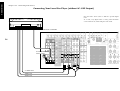
When playing Dolby Digital or DTS-encoded software in
multichannel configuration, the connected audio signal
should be the digital signal.

14
Chapter One : Connecting Your Devices
Connections
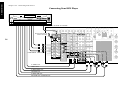
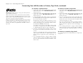
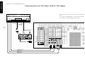
Connecting Your VCR(s)
OPTICAL
VIDEO
4
VIDEO
3
VIDEO
2
CD-R
MD/
TAPE1
CD1
DVD
EXT.CONTROL
RS-232C
DIGITAL IN
COAXIAL
DIGITAL OUT
VIDEO
3 IN
COMPONENT VIDEO
DVD
IN
MONITOR
OUT
MONITOR
OUT
PLAY
IN
PLAY
IN
PLAY
IN
PLAY
IN
REC
OUT
REC
OUT
PLAY
IN
S VIDEO VIDEO
PRE OUTZONE B PRE OUT
R L
AUDIO
R L
FRONT
R L
SURROUND
R LR L
SURROUND BACK
SUB WOOFER
CENTER
VIDEO
R L
B
A
AUDIO
VIDEO1
VIDEO2
VIDEO3
VIDEO4
DVD
FRONT
DVD/
6CH
INPUT
SURROUND
CENTER
SUBWOOFER
PHONO
CD1
REC
OUT
PLAY
IN
MD/
TAPE1
REC
OUT
PLAY
IN
CD-R
REC
OUT
PLAY
IN
CD2/
TAPE2
MONITOR
CENTER
SPEAKER
(6–16Ω)
SURROUND
SPEAKERS
(6–16Ω)
FRONT SPEAKERS
(6–16Ω)
ANTENNA
GND
AM
FM 75Ω
SYSTEM
CONTROL
SL16 TEXT
REMOTE
TV ON/OFF
SENSOR
RELAY
CONTROL
IR OUT
LCD
IR RECEIVER
IN
IR RECEIVER
IN
DVD CONTROL
C
R
L
A
DC5V 10mADC12V 20mA
DC12V
20mA
DC12V 20mA
DE-EMPHASIS
CHANNEL SPACE
P
R
/C
R
P
B
/C
B
Y
P
R
/C
R
P
B
/C
B
Y
P
R
/C
R
P
B
/C
B
Y
50 µs
AM 9kHz
FM 50kHz
75 µs
AM 10kHz
FM 100kHz
REMOTE
IR OUT
LCD
AUDIO IN
VIDEO OUT
S-VIDEO OUT
S-VIDEO IN
AUDIO OUT
VIDEO IN
Page is loading ...
Page is loading ...
Page is loading ...
Page is loading ...
Page is loading ...
Page is loading ...
Page is loading ...
Page is loading ...
Page is loading ...
Page is loading ...
Page is loading ...
Page is loading ...
Page is loading ...
Page is loading ...
Page is loading ...
Page is loading ...
Page is loading ...
Page is loading ...
Page is loading ...
Page is loading ...
Page is loading ...
Page is loading ...
Page is loading ...
Page is loading ...
Page is loading ...
Page is loading ...
Page is loading ...
Page is loading ...
Page is loading ...
Page is loading ...
Page is loading ...
Page is loading ...
Page is loading ...
Page is loading ...
Page is loading ...
Page is loading ...
Page is loading ...
Page is loading ...
Page is loading ...
Page is loading ...
Page is loading ...
Page is loading ...
Page is loading ...
Page is loading ...
-
 1
1
-
 2
2
-
 3
3
-
 4
4
-
 5
5
-
 6
6
-
 7
7
-
 8
8
-
 9
9
-
 10
10
-
 11
11
-
 12
12
-
 13
13
-
 14
14
-
 15
15
-
 16
16
-
 17
17
-
 18
18
-
 19
19
-
 20
20
-
 21
21
-
 22
22
-
 23
23
-
 24
24
-
 25
25
-
 26
26
-
 27
27
-
 28
28
-
 29
29
-
 30
30
-
 31
31
-
 32
32
-
 33
33
-
 34
34
-
 35
35
-
 36
36
-
 37
37
-
 38
38
-
 39
39
-
 40
40
-
 41
41
-
 42
42
-
 43
43
-
 44
44
-
 45
45
-
 46
46
-
 47
47
-
 48
48
-
 49
49
-
 50
50
-
 51
51
-
 52
52
-
 53
53
-
 54
54
-
 55
55
-
 56
56
-
 57
57
-
 58
58
-
 59
59
-
 60
60
-
 61
61
-
 62
62
-
 63
63
-
 64
64


Kenwood KRF-X9995D User manual
- Category
- AV receivers
- Type
- User manual
Ask a question and I''ll find the answer in the document
Finding information in a document is now easier with AI
Related papers
Other documents
-
RCA rc6001p User manual
-
Sherwood R-903R Operating Instructions Manual
-
-
Technicolor - Thomson DPL590HT User manual
-
Pioneer A-109 User manual
-
Radio Shack Stereo Receiver STAV-3780 User manual
-
Audiovox PAV2000DTV User manual
-
Cambridge Audio MI+ Multimedia Explorer User manual
-
Sony TA-FE910R User manual
-
Artsound AMP1250 Datasheet