Page is loading ...

Room Air Conditioner
Service and Parts
Manual
CP10 - CP12 Svc Parts 2010 (05/10)
CP10F10 CP12F10
0
F
Power
Mode
Timer
0n/
0
ff
Fan
Speed
Temp
Cool
Money Saver
®
Fan Only
Dry
hr
Auto
Swing
115Volts

2 Room Air Conditioner
Air Conditioner Service Manual
TABLE OF CONTENTS
Safety Precautions ..........................................................................................................................................3
Dimensions .....................................................................................................................................................6
Outside Dimensions ...................................................................................................................................6
Product Specifications ..................................................................................................................................7
How to operate your Friedrich CP
.......................................................
Controls and Remote Control Operations .................................................................................................8
Disassem bly .................................................................................................................................
....................9
Mechanical Parts.................................................................................................................
.......................9
Air Handling Parts ...................................................................................................................................10
Electrical Parts .........................................................................................................................................11
Refrigerating Cycle...................................................................................................................................12
Schematic Diagram .......................................................................................................................................15
Wiring Diagram.........................................................................................................................................15
Electronic Control Device .........................................................................................................................16
Troubleshooting Guide .................................................................................................................................17
Piping System ........................................................................................................................................17
Troubleshooting Guide .............................................................................................................................18
Exploded View ..............................................................................................................................................26
Replacement Parts List ................................................................................................................................27
.......................
........................8
.......................

Service Manual 3
Safety Precautions
Safety Precautions
To prevent injury to the user or other people and property damage, the following instructions
must be followed.
Incorrect operation due to ignoring instructions will cause harm or damage. The seriousness
is classified by the following indications.
Meanings of symbols used in this manual are as shown below.
WARNING
CAUTION
This symbol indicates the possibility of death or serious injury.
This symbol indicates the possibility of injury or damage to property only.
WARNING
Always install the expansion panel(s).
• Improper assembly or installation may cause
incorrect operation, including injury, fire, and
Do not place the power cord near a heater.
• It may cause fire and electric shock.
Do not use the power cord near flammable
gas or combustibles such as gasoline,
benzene, thinner, etc.
• It may cause explosion or fire.
Do not disassemble or modify products.
• It may cause failure and electric shock.
Be sure not to do.
Be sure to follow the instruction.
electric shock hazards.

4 Room Air Conditioner
Safety Precautions
Plug in the power plug
properly.
• Otherwise, it will cause
electric shock or fire.
Do not operate or stop the
unit by inserting or pulling
out the power plug.
• It will cause electric shock or
fire.
Do not damage or use an
unspecified power cord.
• It will cause electric shock or
fire.
Do not use the socket if it is
loose or damaged.
•• It may cause fire and electric
shock.
Do not operate with wet
hands or in damp
environment.
• It will cause electric shock.
Use the air conditioner on a
single outlet circuit.(see page 7.)
Do not share the outlet with
other appliances.
•
It will cause electric shock or
fire.
Do not modify power corDo not modify poDo not modify po dwer cor
length.
Do not modify po
• •• It will cause electr ic shoc• k or
fire.
Always plug into a
grounded outlet.
• No •• grounding • may cause
electric shock.
Ventilate before operating air
conditionerwhen gas goes
out.
It may cause explosion, fire,
and burn.

Service Manual 5
Safety Precautions
CAUTION
•
•
•
•
•
If water enters the product, turn off the the
power switch of the main body of appliance.
Contact service center after taking the power-
plug out from the socket.
• It will cause electric shock or failure of
machine.
Do not clean the air conditioner with water.
• Water may enter the unit and degrade the
insulation. It may cause an electric shock.
Never touch the metal parts of the unit
when removing the filter.
Do not block the inlet or outlet.
They are sharp and may cause injury.
It may cause failure of appliance or
performance deteriorate.
Ensure that the outer caseis not damaged
by age orwear.
Leaving it damaged couldresult in the air
conditioner falling out of the window, creating
a safety hazard.
Be cautious not to touch the sharp edges
when installing.
It may cause injury.
Sharp
edges

6 Room Air Conditioner
Dimensions
Dimensions
Outside Dimensions
This symbol alerts you to the risk of electric shock.
This symbol alerts you to hazards that could cause harm to the
air conditioner.
This symbol indicates special notes.
NOTICE
Symbols Used in this Manual
353(13
7
/8")
470(18
1
/2")525(20
11
/16")

Se rvice Manual
Specfications
Product Specifications
Ser 7
Product Specifications
Ser
Product SpecificationsProduct Specifications
POWER SUPPLY
COOLING CAPACITY (Btu/h)
INPUT (W)
RUNNING CURRENT (A)
E.E.R (BTU/W
.
h)
INDOOR ( F)
OUTDOOR ( F)
REFRIGERANT (R410) CHARGE
EVAPORATOR
CONDENSER
FAN, INDOOR
FAN, OUTDOOR
FAN SPEEDS, FAN/COOLING
FAN MOTOR
OPERATION CONTROL
ROOM TEMP. CONTROL
AIR DIRECTION CONTROL
CONSTRUCTION
PROTECTOR
COMPRESSOR
FAN MOTOR
POWER CORD
DRAIN SYSTEM
(W x H x D)
(mm)
CP12F10
MODELS
ITEMS
OPERATING
CONDITION
* DB:Dry Bulb
**
WB:Wet Bulb
1Ø , 115, 60Hz
12,000
1,110
10.2
10.8
80 (DB)* 67(WB)**
95 (DB)* 75(WB)**
530g(18.7oz)
Ø9.52, 2ROW 13STACKS
Ø5 , 3ROW 18STACKS
TURBO FAN
PROPELLER TYPE FAN WITH SLINGER RING
3/3
6 POLES
REMOTE CONTROLLER
THERMISTOR
HORIZONTAL LOUVER (UP & DOWN), VERTICAL LOUVER (RIGHT&LEFT)
SLIDE IN-OUT CHASSIS
OVERLOAD PROTECTOR
INTERNAL THERMAL PROTECTOR
3 WIRE WITH GROUNDING
ATTACHMENT PLUG (CORD-CONNECTED TYPE)
DRAIN PIPE OR SPLASHED BY FAN SLINGER
380 x 600 x 555
.
H x
.0
.
.0
.
OUTSIDE DIMENSION
(inch)
.0
235/8x1431/32x225/16
CP10F10
10,000
920
8.5
540g(19.0oz)
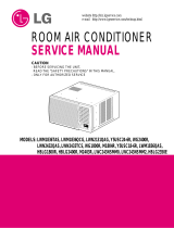
Operation
• DESIGNED FOR COOLING ONLY
• POWERFUL AND INCREDIBLE COOLING
• TOP-DOWN CHASSIS FOR THE SIMPLE INSTALLATION AND SERVICE
• BUILT-IN ADJUSTABLE THERMOSTAT
• WASHABLE ONE-TOUCH FILTER
• COMPACT SIZE

0
F
Power
Mode
Timer
0n/
0
ff
Fan
Speed
Temp
Cool
Money Saver
®
Fan Only
Dry
hr
Auto
Swing
1
2
3
4
5
7
Air
P urifier
Power
Temp
Mode
Timer
A
S wing
Fan S peed
1
2
4
3
5
Auto
Swing
6
6
6. AUTO SWING
This button can automatically control the air flow
direction.
7
Service Manual 8

Disassembly
Disassembly
Mechanical Parts
Before the following disassembly, POWER SWITCH set to OFF and disconnect the power cord.
1. FRONT GRILLE
1. Open the lnlet grille upward or downward.
2. Remove the screw which fastens the front grille.
3. Pull the front grille from the right side.
4. Remove the front grille.
5. Re-install the component by referring to the
removal procedure, above.(See Figure 1)
2. CABINET
1. After disassembling the FRONT GRILLE, remove
the 2 screws which fasten the cabinet at both
sides.
2. Remove the 2 screws which fasten the cabinet at
back.
3. Pull the base pan forward. (See Figure 2)
4. Remove the cabinet.
5. Re-install the component by referring to the
removal procedure, above.
3. CONTROL BOX
1. Disconnect the unit from the power source.
2. Remove the front grille.
3. Remove the cabinet.
4. Remove the screw which fastens the control box
cover.
5. Remove the housing which connects motor wire
in the control box.
6. Remove the 3 leads from the compressor.
7.Discharge the capacitor by placing a 20,000
ohmresistor across the capacitor terminals.
8. Remove the 2 screws which fasten the control
box.(See Figure 19)
9. Pull the control box forward completely.
10. Re-install the components by referring to the
removal procedure, above. (See Figure 3)
Figure 1
Figure 3
Figure 2
Service Manual 9

10 Room Air Conditioner
Disassembly
Air Handling Parts
1. AIR GUIDE AND BLOWER
1. Remove the front grille.
2. Remove the cabinet.
3. Remove the control box.
4. Remove the 3 screws which fasten the brace.
5. Remove the brace.
6. Remove the 2 screws which fasten the evaporator.
7. Move the evaporator forward and pulling it upward
slightly. (See Figure 4)
8. Move the evaporator to the left carefully.
9. Pull out the hook of orifice by pushing the tabs and
remove it. (See Figure 5)
10. Remove the clamp with a hand plier which
secures the blower.
11. Remove the blower.
12. Remove the 4 screws which fasten the air guide
from the barrier.
13. Move the air guide backward, pulling out from the
base pan.
14. Re-install the components by referring to the
removal procedure, above.
2. FAN AND SHROUD
1. Remove the cabinet.
2. Remove the brace.
3. Remove the 3 screws which fasten the condenser.
4. Move the condenser to the left carefully.
5. Remove the clamp which secures the fan.
6. Remove the fan and then pull out the shroud.
(See Figure 6)
7. Re-install by referring to the removal procedure.
Figure 4
Figure 5
Figure
6

Service Manual 11
Electrical Parts
1. Remove the cabinet.
2. Remove the evaporator.
3. Remove the orifice.
4. Remove the blower.
5. Remove the fan.
6. Remove the control box cover and housing of the
motor in the control box.
7. Remove the 2 screws which fasten the motor from
the mount motor. (See Figure 7)
8. Remove the motor.
9. Re-install the components by referring to the
removal procedure, above.(See Figure 7)
Figure 7
3. MOTOR
1. OVERLOAD PROTECTOR
1. Remove the cabinet.
2. Remove the nut which fastens the terminal cover.
3. Remove the terminal cover. (See Figure 8)
4. Remove all the leads from the overload protector.
5. Remove the overload protector.
6. Re-install the component by referring to the
removal procedure, above.
Figure 8
Disassembly
2. COMPRESSOR
1. Remove the cabinet.
2. Discharge the refrigerant system using a Freon
TM
Recovery System.
If there is no valve to attach the recovery system,
install one (such as a WATCO A-1) before venting
the Freon
TM
. Leave the valve in place after
servicing the system.
3. Remove the overload protector.
4. After purging the unit completely, unbraze the
suction and discharge tubes at the compressor
connections.
5. Remove the 3 nuts and the 3 washers which
fasten the compressor.
6. Remove the compressor. (See Figure 9)
7. Re-install the components by referring to the
removal procedure, above.
Figure 9

MODEL : TOUCH & REMOTE CONTROL TYPE MODEL
Disassembly
12 Room Air Conditioner
1. Remove the control box.
2. Remove the screw which fasten control panel from
control box.
3. Remove the screw which located in the front.
4. Open the bottom side of control box.
5. Remove the screw and the clamp which fastens
the capacitor.
6. Disconnect all the leads of capacitor terminals.
7. Re-install the components by referring to the
removal procedure, above. (See Figure 10)
Figure 10
4. POWER CORD
Figure 11
1. Remove the control box.
2. Open the control box.
3. Disconnect the grounding screw from the control
box.
4. Disconnect the 2 receptacles.
5. Remove a screw which fastens the clip cord.
(See Figure 11)
6. Remove the power cord.
7. Re-install the component by referring to the above
removal procedure, above.
(Use only one ground-marked hole for ground
connection.)
8. If the supply cord of this appliance is damaged, it
must be replaced by the special cord. (The
special cord means the cord which has the same
specification marked on the supply cord attached at
the unit.)
Refrigerating Cycle
CAUTION: Discharge the refrigerant system using a Freon
TM
Recovery System. If there is no valve
to attach the recovery system, install one (such as a WATCO A-1) before venting the Freon
TM
. Leave
the valve in place after servicing the system.
1.
CONDENSER
Figure 12
1. Remove the cabinet.
2. Remove the 3 screws which fasten the
brace.
3. Remove the 3 screws which fasten the condenser
and shroud.
4. After discharging the refrigerant completely,
unbraze the interconnecting tube at the condenser
connections.
5. Remove the condenser carefully.
6. Re-install the component by referring to notes.
(See Figure 12)
3. CAPACITOR

13 Room Air Conditioner
Disassembly
— Replacement of the refrigeration cycle.
1. When replacing the refrigeration cycle, be sure to
Discharge the refrigerant system using a Freon
TM
recovery System.
If there is no valve to attach the recovery system,
install one (such as a WATCO A-1) before venting
the Freon
TM
. Leave the valve in place after
servicing the system.
2. After discharging the unit completely, remove the
desired component, and unbraze the pinch-off
tubes.
3. Solder service valves into the pinch-off tube ports,
leaving the valves open.
4. Solder the pinch-off tubes with Service valves.
5. Evacuate as follows.
1) Connect the vacuum pump, as illustrated figure
14A.
2) Start the vacuum pump, slowly open manifold
valves A and B with two full turns counterclock-
wise and leave the valves open.
The vacuum pump is now pulling through valves
A and B up to valve C by means of the manifold
and entire system.
CAUTION: If high vacuum equip-
ment is used, just crack valves A
and B for a few minutes, then open
slowly with the two full turns counter-
clockwise. This will keep oil from foaming
and being drawn into the vacuum pump.
3) Operate the vacuum pump vaccum for 20 to 30
minutes, until 600 microns of vaccum is
obtained. Close valves A and B, and observe
vacuum gauge for a few minutes. A rise in pres-
sure would indicate a possible leak or moisture
remaining in the system. With valves A and B
closed, stop the vacuum pump.
4) Remove the hose from the vacuum pump and
place it on the charging cylinder. See figure
14B. Open valve C.
Discharge the line at the manifold connection.
5) The system is now ready for final charging.
6. Recharge as follows :
1) Refrigeration cycle systems are charged from
the High-side. If the total charge cannot be put
in the High-side, the balance will be put in the
suction line through the access valve which you
installed as the system was opened.
2) Connect the charging cylinder as shown in figure
33B.
With valve C open, discharge the hose at the
manifold connection.
3) Open valve A and allow the proper charge to
enter the system. Valve B is still closed.
4) If more charge is required, the high-side will not
take it. Close valve A.
5) With the unit running, open valve B and add the
balance of the charge.
a.
Do not add the liquid refrigerant to the Low-side.
b. Watch the Low-side gauge; allow pressure to
rise to 39 lbs.
c. Turn off valve B and allow pressure to drop.
d. Repeat steps b. and c. until the balance of the
charge is in the system.
6) When satisfied the unit is operating correctly,
use the pinch-off tool with the unit still running
and clamp on to the pinch-off tube. Using a tube
cutter, cut the pinch-off tube about 2 inches from
the pinch-off tool. Use sil-fos braze and braze
pinch-off tube closed. Turn off the unit, allow it to
set for a while, and then test the leakage of the
pinch-off connection.
NOTICE
2. EVAPORATOR
3. CAPILLARY TUBE
Figure 13
1. Remove the cabinet.
2. Remove the 2 screws which fasten the evaporator.
3. Move the evaporator sideways carefully.
4. After discharging the refrigerant completely,
unbraze the interconnecting tube at the evaporator
connections.
5. Remove the evaporator carefully.
6. Re-install the component by referring to notes.
(See Figure 1)
1. Remove the cabinet.
2. After discharging the refrigerant completely,
unbraze the interconnecting tube at the capillary
tube.
3. Remove the capillary tube.
4. Re-install the component by referring to notes.

Service Manual 14
Disassembly
Equipment needed: Vacuum pump, Charging cylinder, Manifold gauge, Brazing equipment. Pin-off tool capable
of making a vapor-proof seal, Leak detector, Tubing cutter, Hand Tools to remove components, Service valve.
A
COMPOUND GAUGE
EVAPORATOR
(LOW PRESSURE SIDE)
COMPRESSOR
CAPILLARY TUBE
CONDENSER
(HIGH PRESSURE SIDE)
SEE INSETS
BELOW
MANIFOLD
GAUGE
B
Figure 14A-Pulling Vacuum
Figure 14B-Charging
A
B
EXTERNAL
VACUUM PUMP
A
CHARGING
CYLINDER
LOW
HI
B
C

Service Manual 15
Schematic Diagram
Circuit Diagram
MODEL : TOUCH & REMOTE CONTROL TYPE MODEL
LOCATION
NO.
1
2
3
4
5
6
7
8
Q'TY
PER SET
1
1
1
1
1
1
1
1
DESCRIPTION
POWER CORD ASSEMBLY
FAN MOTOR
COMPRESSOR
DISPLAY P.W.B ASSEMBLY
MAIN P.W.B ASSEMBLY
THERMISTOR
CAPACITOR
OWERLOAD PROTECTOR
(SMPS)
250V/T2A
(250V/T3.15A)
MEZ62420717
WH
(BL)

16 Room Air Conditioner
Electronic Control Device
Schematic Diagram

17 Room Air Conditioner
Troubleshooting Guide
Troubleshooting Guide
Piping System
Figure 15 is a brief description of the important components and their function in what is called the refrigeration
system. This will help you to understand the refrigeration cycle and the flow of the refrigerant in the cooling cycle.
MOTOR
COMPRESSOR
OIL
(LIQUID REFRIGERANT)
CAPILLARY TUBE
OUTSIDE COOLING
AIR FOR REFRIGERANT
PASS THROUGH
SUCTION LINE
COOL LOW PRESSURE VAPOR
COOLED
AIR
COMPLETE LIQUID
BOIL OFF POINT
LIQUID
PRESSURE
DROP
ROOM AIR HEAT LOAD
VAPOR INLET
HOT
DISCHARGED
AIR
LIQUID OUTLET
HIGH PRESSURE VAPOR
LIQUID REFRIGERANT
LOW PRESSURE VAPOR
ROOM AIR CONITIONER
EVAPORATOR COILS CONDENSER COILS
CYCLE OF REFRIGERATION
Figure 15
CAPILLARY TUBE
COMPRESSOR
BLOWER
EVAPORATOR COIL
CONDENSER COIL
FAN
MOTOR

Service Manual 18
Troubleshooting Guide
Troubleshooting Guide
In general, possible trouble is classified in two kinds.
The one is called Starting Failure which is caused from an electrical defect, and the other is ineffective Air
Conditioning caused by a defect in the refrigeration circuit and improper application.
Unit runs but poor cooling.
Ineffective Cooling
Satisfactory operation
with temperature
difference of inlet & outlet
air; 44~50°F (7~10°C)
Replacement of unit if
the unit is beyond repair.
Check outdoor coil
(heat exchanger) and
fan operation.
Check heat load
increase.
Check cold air
circulation for smooth
flow.
Check gas leakage.
Clean condenser.
Not on separate circuit
Check inside gas
pressure.
Adjust refrigerant
charge.
Malfunction of
compressor.
Replacement of
compressor.
Check clogging in refrigera-
tion circuit.
Repair clogging in
refrigeration circuit.
Dirty indoor coil
(heat exchanger)
Repair gas leak.
Malfunction of fan.
Clogging of air filter.
Obstruction at air outlet.
Remove obstruction.

19 Room Air Conditioner
Troubleshooting Guide
Fails to Start
Improper thermistor
setting
Loose terminal
connection
Improper wiring
Check of power source.
Drop of power voltage.
Capacitor check.
Replacement.
Check of control panel
setting.
Compressor fails only to
start.
Defect of compressor
capacitor.
Replacement of compressor
(Motor damaged).
Irregular motor insulation (Ω)
Irregular motor resistance (Ω)
Check of circuit breaker
and fuse.
Check control panel.
Fan only fails to start.
Improper wiring.
Defect of fan motor
capacitor.
Replacement of fan motor.
Regular but fails to start.
Replacement of compressor.
(Locking of piston, metal.)
Irregular motor
resistance (Ω)
Irregular motor
insulation (Ω)

Service Manual 20
Troubleshooting Guide
■ MODEL : BG8000ER, WG8000RY4, WG1000RY4
ELECTRIC PARTS TROUBLESHOOTING GUIDE:
Possible Trouble 1
• The unit does not operate.
Is the Trans input power
AC 115V?
Is the Trans output power
about AC 14V?
Is shorted the Trans. output?
Is output Voltage of IC01D
DC 12V?
Is output Voltage of IC02D
DC 5V?
Is the voltage No.18 of Micom
DC 5V?
Exchange Main P.W.B Ass'y.
Is the
connection between
Main and Display
all right?
Is the reset circuit all right?
(The No.14 of Micom
is 5V.)
•
Check the Fuse.
•
Check the wiring diagram.
•
Check the Main
P.W.B pattern.
• Exchange the Trans.
•
Exchange D02D~D05D.
• Exchange IC01D.
• Exchange IC02D.
• Exchange IC01A.
• Connect connector
exactly.
• Check the
P.W.B
pattern.
NO
NO
NO
NO
NO
NO
NO
YES
YES
YES
YES
YES
YES
YES
NO
YES
/