Page is loading ...

4.4 Battery charger(BC-6158)
4-12
4.4 Battery charger (BC-6158)
4.4.1 Connection of battery charger and battery monitor circuit
Battery charger BC-6158 is controlled from the battery control panel of the console
panel.
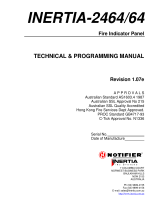
Fig. 4.4.1 Connection of battery charger and battery monitor circuit
The battery monitor circuit (05P0607) monitors battery voltage.
If battery voltage drops to 22 V, [LOW] indicator comes on and the buzzer sounds.
With “BATT CHARGER switch” set to “AUTO”, the charger starts charging the battery
when the battery voltage drops to 24.5 to 25.0 V, and stops charging when the battery is
charged by 28.0 to 28.5 V automatically. If the switch is set to “MANUAL”, the battery
is charged in continuity. The signal to control charging is “3. CHARGE-L” signal which
turns ON/OFF relay K1 on the AC power supply line of BC-6158.
AC FAIL signal from PR-850A (AR), a contact signal of the relay is output when AC
supply is turned “OFF” and switched to the battery.
This signal is supplied to “2. EMG-L” of the battery monitor board to indicate “IN
USE”. This signal is also supplied to FS-5000/2550/1562-25 and automatically reduces
the transmission power to 60 to 70 W.
Note) The “AUTO” position is provided to prevent over discharge of the battery.
This “AUTO” position is not intended to use both the battery and AC/DC supplies
at the same time for so called “floating operation”.
Battery
BC-6158
TB1
1. BATT IN+
2. BATT IN-
TB3
TB2
1. AC(U)
2. AC(V)
AC100/220V
AC100/220V AC100/220V
60A
RC-1800T only
SB-180
1. (+)BATT OUT
2. (-)BATT OUT
PR-850A
PR-850AR
(RC-1800T)
PR-300
1. 24V 2. EMG L
4. BATT+
5. BATT-
6. LAMP 2(NC)
7. LAMP 1
05P0607
3. (+)BATT OUT
4. (-)BATT OUT
5. 24V
6. CHARGE
7. 0V
24V
Back-up
24V Back-up
24V Back-up
24V
Back-up
AC FAIL
AC FAIL
MF/HF SSB
EMG
Lamp
3. CHRG-L
BATT CH. SW
AUTO
OFF
CHARGE
EMG LIGHT
ON
OFF
V
A
24V OUT
Illuumination
Lamp
IN USE
CHARGE
AC iN
K1
REC
T1
Primary system
Duplicate system

4.4 Battery charger(BC-6158)
4-14
V
I
28V
4.4.3 Battery charger (BC-6158)
Battery charger BC-6158 can charge clad type or pasteboard vent type batteries of up to
300 AH. It is a constant voltage/current charger which supplies a constant voltage of 28
V and a constant charging current of 20 A (30 A).
The power supply to the charger is connected to a tap of transformer T1 which is
selected according to the supply voltage.
The maximum charging current differs according to the capacity of the battery to be
charged. For example, for a battery of 200 AH the maximum charging current is 20 A
and for a 300 AH battery the current is 30 A. VR2 adjusts the maximum current to 20 A
or 30 A. VR1 adjusts the output voltage of the charger to 28 V. The thermal sensor is
mounted on the heat radiator of the charger, and it operates when the sensor detects a
temperature of 60 degrees.
20A(30A)
Fig. 4.4.4
Fig. 4.4.5 BC-6518 block diagram
110V
100V
0V
110V
100V
0V
K1
T1
U1/U2
Q1
Q4/Q5
CR3/Q3
Q2
VR1
VR2
30A
Breaker
CP1
FAN
S1
6o degrees
thermal sensor
FM1
CR2
TB 1
AC IN
TB 3
TB 2
(1, 2)
24V 5
CHARGE 6
0V 7
1 BATT+
2 BATT-
TB 3
1 BATT+
2 BATT-
3 BATT+
4 BATT-
R1,2,3,4
Full wave rectifier
Power conrol
Over current
detector
Voltage error
detctor
AMP.
05P0659 board
VR2
(Over current ADJ. VR:
Adjust to 20A)
VR1
(Over voltage ADJ. VR:
Adjust to 28V)
S1: 60 degrees
thermal sensor
Fig. 4.4.6 BC-6158 left side

3.4 BC-6158
3-12
3.4 BC-6158: Battery charger unit
T1
TB3
Upper terminal:TB2
Lower terminal:TB1
Breaker: :30A
(CP1)
K1
(Input rlay)
Rectifier
(U1)
Rectifier
(U2)
05P0659 board
R3/4
(0.01ohms)
Q1
S1: 60 degrees
thermal sensor
R1/2
(0.5Ω/50W)
CR2
C3
C1
Fig. 3.4.1 BC-6158
05P0659
Q1
R3/4
(0.01ohms)
S1: 60 degrees
thermal sensor
VR2
(Over current ADJ. VR.:
Adjust to 20A)
VR1
(Over voltage ADJ. VR.:
Adjust to 28V)
Fig. 3.4.2 BC-6158 left side
/