August
1975
FORM:
OM-162
Effective
with
serial
No.
HE844784
MODEL
BWC-300M
APA
BWC-500MAPA
STOCK
NO.
900
302
900
311
MODEL/STOCK
NO.
SERIAL/STYLE
NO.
DATE
PURCHASED
ADDITIONAL
COPY
PRICE
90
CENTS
OWNERS
MANUAL
MILLER
ELECTRIC
MFG.
Co.
APPLETON,
WISCONSIN,
USA
54911
NWSA
CODE
NO.
4579

I
QQOQQ~Q~QQQOOQQ9QJ9QQ~QJQQQQQJQQQ~QQQQQQJfi
0D
DTbTOTO
o
OTb
o
ro
o~OTb
b~bTOTrb
oOTb
OTrOTOT~r~+~OoT~TOOTO
TOT1IO
bTb
ft0
OTO
o
~O
CD
C
~
(
~
C
~
CD
CD
WARRANTY
C
MILLER
Electric
Mfg.
Co.,
Appleton,
Wisconsin,
warrants
all
new
equipment
to
be
free
from
defects
in
C)
c
material
and
factory
workmanship
for
the
periods
indicated
below,
provided
the
equipment
is
installed
and
C
C)
-
C)
operated
according
to
manufacturers
instructions.
C)
C)
C)
C)
MILLER
Electnc
Mfg.
Co.sobligation,
under
thiswarranty,
is
limited
to
replacingorrepairinganydefective
C
C)
c
part
or
correcting
any
manufacturing
defect
without
charge
during
the
warranty
period
if
MILLERS
inspec
c
tion
confirms
the
existence
of
such
defects.
MILLERS
option
of
repair
or
replacement
will
be
f.o.b.
factory
at
C)
C
)
Appleton,
Wisconsin
or
f.o.b.
a
MILLER
authorized
service
facility,
and
therefore
no
compensation
for
trans
portation
costs
of
any
kind
will
be
allowed.
C
)
l
)
C
C
C
C
The
warranty
period,
beginning
on
the
date
of
sale
to
the
original
purchaser-user
of
the
equipment,
will
be
as
i
follows:
1.
Arc
welders,
power
sources,
and
components
1
year
l
C
C
C
2.
Original
main
power
rectifiers
3
years
(unconditionally)
3.
MHFC-L1
Feeder,
MHG-35C1,
20E,
20K,
C
C
C
C
C
and
all
guns
and
torches
90
days
C
i
C
4.
All
other
Millermatic
Feeders
1
year
5.
Mag-Diesel
engine
on
DEL-200
6
months
C
C
C
C
C
6.
All
other
engines
1
year
C
C
C
I
CD
C
Engine
Warranties
are
covered
by
the
engine
manufacturers,
subject
to
their
procedures
and
to
be
handled
C
CD
through
their
authorized
local
Service
Stations
or
agencies.
No
warranty
will
be
made
in
respect
to
trade
C
I
C
C
accessories,
such
being
subject
to
the
warranties
of
their
respective
manufacturers.
-
CD
C
I
CD
C
C
C)
C
MILLER
Electric
Mfg.
Co.
will
not
be
liable
for
any
loss
or
consequential
damage
or
expense
accruing
c
directly
or
indirectly
from
the
use
of
equipment
covered
in
this
warranty.
C
C
CD
C
C
C)
C
I
This
warranty
supersedes
all
previous
MILLER
warranties
and
is
exclusive
with
no
other
guarantees
or
~
C
C
C)
C
C
warranties
expressed
or
implied.
C
C
C)
QIIOJJJJJJ
tO
0
tQJI.LQ
O~O
QO1
Q
LQtQ
Q
0
W
0
QLLLO
0
QJ
OQLLQQQJ
0
tQ
~0
~OJJLttQ
-
rrom
o-rOTO-o
oo-om
o-o-rro
OOTOTO
or.-~
OPTIONAL
ACCESSORIES
No.
34
Running
Gear
(Stock
No.
040
018)
Carries
welder,
water
coolant
system
and
two
gas
cylinders.
Designed
for
Model
BWC-300
MAPA
only.
RHC-3
(Stock
No.
040
056)
Remote
hand
amperage
control
for
all
Gold
Star
300
models.
Supplied
with
20
cable
and
plug.
RFC-3A
(Stock
No.
040
068)
Remote
foot
amperage
control
on
all
Gold
Star
300
models.
Supplied
with
20
cable
and
plug.
RFC-23AG
(Stock
No.
041
161)
Remote
foot
control
for
amperage
and
contactor
on
all
Gold
Star
300
models.
Supolied
with
20
cable
and
plug.
RFS-2G
(Stock
No.
041
160)
Maintained
contact
type
foot
switch
for
A
panel
operation
or
can
be
converted
to
a
momentary
contact
switch
for
B
type
operation.
Used
for
foot
on-off
operation
on
all
P,
A/BP
and
A/B/SP
models.
Supplied
wth
20~
cable
with
plug.

CERTIFICATE
NAME
OF
EQUIPMENT:________________________
MODEL
NO..
SERIAL
NO._________________________
DATE
This
equipment
has
been
type-tested
under
standardized
field
test
conditions
as
recommended
by
the
Joint
Industry
Committee
on
High
Frequency
Stabilized
Arc
Welding
Machines
found
to
rad
iate
less
than
10
microvolts
per
meter
at
a
distance
of
one
mile,
the
maximum
allowable
limit
established
by
the
Federal
Communications
Commission
for
equipment
of
this
type.
Installations
using
this
equipment
on
the
basis
of
these
tests,
may
reasonably
be
expected
to
meet
the
radiation
limitations
established
by
the
Federal
Communications
Commission,
only
when
in
stalled,
operated
arid
maintained
as
specified
in
the
instruction
book
provided.
USERS
CERTIFICATION
The
welding
equipment
identified
above
has
been
installed
in
accordance
with
the
specific
in
structions
applicable
to
this
model
as
outlined
in
the
instruction
book
furnished,
It
is
being
used
only
for
the
purpase
for
which
it
was
intended
and
is
being
mainained
and
operated
in
accord
ance
with
the
manufacturers
instructions.
Dote
Installed.


TABLE
OF
CONTENTS
Paragraph
No.
Page
No.
SECTION
1
SAFETY
RULES
FOR
OPERATION
OF
ARC
WELDING
POWER
SOURCE
1
-
1.
Introduction
1
1
-
2.
General
Precautions
1
1
-
3.
Arc
Welding
3
1
-
4.
Standards
Booklet
Index
4
SECTION
2
INTRODUCTION
2-
1.
General
5
2-2.
Receiving-Handling
5
2-3.
Description
5
2-4.
Safety
5
SECTION
3
INSTALLATION
3-1.
Location
5
3
-
2.
Electrical
Input
Connections
6
3
-
3.
Secondary
Connections
7
3
-
4.
Remote
Amperage
Control
Connections
7
3-
5.
Con
tactor
Control
Connections
7
3-
6.
Water
Valve
Connections
7
3-
7.
Shielding
Gas
Valve
Connections
7
3-
8.
External-Internal
High
Frequency
Selection
7
3-
9.
Automatic-Manual
Terminal
Strip
8
3-10.
External
Start
Switch
Connections
8
SECTION
4
FUNCTION
OF
CONTROLS
4-1.
Power
Switch
9
4
-
2.
Range
Switch
9
4.
3.
Amperage
Adjustment
Control
9
4
-
4.
Remote
Amperage
Control
Receptacle
&
Switch
9
4-
5.
Start
Adjustment
9
4-
6.
High-Frequency
Switch
9
4-
7.
High-Frequency
Intensity
Control
9
4-8.
High
Frequency
DelayTimer
10
4-
9.
Con
tactor
Control
Receptacle
10
4-10.
Post-FlowTimer
10
4-11.
DutyCycle
10
4-12.
Volt-Ampere
Curve
10
SECTION
5
MAINTENANCE
5-1.
Rectifier
12
5-2.
Fan
Motor
12
5-3.
Transformer
12
5-4.
Spark
Gap
12
SECTION
6
TROUBLESHOOTING

Paragraph
No.
Page
No.
SECTION
7
CERTIFICATION
FOR
HIGH
FREQUENCY
ARC
WELDING
EQUIPMENT
7-1.
General
15
7
-
2.
General
Information
15
7-a
PowerService
15
7-4.
WeldingMachine
15
7-
5.
Welding
Leads
16
7
-
6.
Wiring
In
The
Vicinity
Of
The
Welding
Area
16
7-7.
Grounds
16
7-8.
Metal
Building
16
7-
9.
Individual
Installation
Certification
17
7-10.
Check
List
17
PARTS
LIST

~SECTION
i-SAFETY
RULES
FOR
OPERATION
OF
ARC
WELDING
POWER
SOURCE
1-1.
INTRODUCTION
We
learn
by
experience.
Learning
safety
through
personal
experience
like
a
child
touching
a
hot
stove
is
harmful,
waste
ful,
and
unwise.
Let
the
experience
of
others
teach
you.
Safe
practices
developed
from
experience
in
the
use
of
weld
ing
and
cutting
are
described
in
this
manual.
Research,
devel
opment,
and
field
experience
have
evolved
reliable
equipment
and
safe
installation,
operation,
and
servicing
practices.
Acci
dents
occur
when
equipment
is
improperly
used
or
main
tained.
The
reason
for
the
safe
practices
may
not
always
be
given.
Some
are
based
on
common
sense,
others
may
require
technical
volumes
to
explain.
It
is
wiser
to
follow
the
rules.
Read
and
understand
these
safe
practices
before
attempting
to
install,
operate,
or
seivice
the
equipment.
Comply
with
these
procedures
as
applicable
to
the
particular
equipment
used
and
their
instruction
manuals,
for
personal
safety
and
for
the
safety
of
others.
Failure
to
obseive
these
safe
practices
may
cause
serious
in
jury
or
death.
When
safety
becomes
a
habit,
the
equipment
can
be
used
with
confidence.
Responsibilities
of
installer,
user,
and
serviceman.
Installa
tion,
operation,
checking,
and
repair
of
this
equipment
must
be
done
only
by
a
competent
person,
experienced
with
such
equipment.
These
safe
practices
are
divided
into
two
Sections:
1
General
Precautions,
common
to
arc
welding
and
cutting;
and
2
-
Arc
Welding
(and
CuttingHonly).
Reference
standards:
Published
Standards
on
safety
are
also
available
for
additional
and
more
complete
procedures
than
those
given
in
this
manual.
They
are
listed
in
the
Standards
Index
in
these
safety
rules.
ANSI
Z49.1
is
the
most
complete.
The
National
Electrical
Code.
Occupation
Safety
and
Health
Administration,
local
industrial
codes,
and
local
inspection
requirements
also
provide
a
basis
for
equipment
installation,
use,
and
service.
1-2.
GENERAL
PRECAUTIONS
A.
Bum
Prevention
Wear
protective
clothing
-
leather
(Or
asbestos)
gauntlet
gloves,
hat,
and
high
safety-toe
shoes.
Button
shirt
collar
and
pocket
flaps,
and
wear
cuffless
trousers
to
avoid
entry
of
sparks
and
Slag.
Wear
helmet
with
safety
goggles
or
glasses
with
Side
shields
underneath,
appropriate
filter
lenses
or
plates
(protected
by
clear
cover
glass).
This
is
a
MUST
for
welding
or
cutting,
(and
chipping)
to
protect
the
eyes
from
radiant
energy
and
flying
metal.
Replace
cover
glass
when
broken,
pitted,
or
spattered.
See
1-3A.
Avoid
oily
or
greasy
clothing.
A
spark
may
ignite
them.
Hot
metal
such
as
electrode
stubs
and
workpieces
should
never
be
handled
without
gloves.
Medical
first
aid
and
eye
treatment.
First
aid
facilities
and
a
qualified
first
aid
person
should
be
~railable
for
each
shift
unless
medical
facilities
are
close
by
for
immediate
treatment
of
flash
burns
of
the
eyes
and
skin
burns.
Ear
plugs
should
be
worn
when
working
on
overhead
or
in
a
confined
space.
A
hard
hat
should
be
worn
when
others
work
overhead.
Flammable
hair
preparations
should
not
be
used
by
persons
intending
to
weld
or
cut.
B.
Toxic
Fume
Prevention
Adequate
ventilation.
Severe
discomfort,
illness
or
death
can
result
from
fumes,
vapors,
heat,
or
oxygen
enrichment
or
depletion
that
welding
(or
cutting)
may
produce.
Prevent
them
with
adequate
ventilation
as
described
in
ANSI Stan
dard
Z49.1
listed
1
in
Standards
index.
NEVER
ventilate
with
oxygen.
Lead,
cadium,
zinc,
mercury,
and
beryllium
bearing
and
simi
lar
materials,
when
welded
(Or
cut)
may
produce
harmful
concentrations
of
toxic
fumes.
Adequate
local
exhaust
venti
lation
must
be
used,
or
each
person
in
the
area
as
well
as
the
operator
must
wear
an
air-supplied
respirator.
For
beryllium,
both
must
be
used.
Metals
coated
with
or
containing
materials
that
emit
toxic
fumes
should
not
be
heated
unless
coating
is
removed
from
the
work
surface,
the
area
is
well
ventilated,
or
the
operator
wears
an
air-supplied
respirator.
Work
in
a
confined
space
only
while
it
is
being
ventilated
and,
if
necessary,
while
wearing
an
air-supplied
respirator.
Gas
leaks
in
a
confined
space
should
be
avoided.
Leaked
gas
in
large
quantities
can
change
oxygen
concentration
danger
ously.
Do
not
bring
gas
cylinders
into
a
confined
space.
Leaving
confined
space,
shut
OFF
gas
supply
at
source.
The
space
will
then
be
safe
to
re-enter,
if
downstream
valves
have
been
accidently
opened
or
leftopen.
Vapors
from
chlorinated
solvents
can
be
decomposed
by
the
heat
of
the
arc
(or
flame)
to
form
P)-3OSGENE,
a
highly
toxic
gas,
and
other
lung
and
eye
irritating
products.
The
ultra
violet
(radiant)
energy
of the
arc
can
also
decompose
tn
chloroethylene
and
perchloroethylene
vapors
to
form
phos
gene.
DO
NOT
WELD
or
cut
where
solvent
vapors
can
be
drawn
into
the
welding
or
cutting
atmosphere
or
where
the
radiant
energy.can
penetrate
to
atmospheres
containing
even
minute
amounts
of
trichlorethylene
or
perchlorethylene.
C.
Fire
and
Explosion
Prevention
Causes
of
fire
and
explosion
are:
combustibles
reached
by
the
arc,
flame,
flying
sparks,
hot
slag
or
heated
material;
misuse
of
compressed
gases
and
cylinders;
and
short
circuits.
Be
aware
that
flying
sparks
or
falling
slag
can
pass
through
cracks,
along
pipes,
through
windows
or
doors,
and
through
wall
or
floor
openings,
Out
of
sight
of
the
goggled
operator.
Sparks
and
slag
can
fly
35
feet.
To
prevent
fires
and
explosion:
Keep
equipment
clean
and
operable,
free
of
oil,
grease,
and
(in
electrical
parts)
of
metallic
particles
that
can
cause
short
circuits.
If
combustibles
are
in
area,
do
NOT
weld
or
cut.
Move
the
work
if
practicable,
to
an
area
free
of
combustibles.
Avoid
paint
spray
rooms,
dip
tanks,
storage
areas,
ventilators.
If
the
work
can
not
be
moved,
move
combustibles
at
least
35
feet
away
out
of
reach
of
sparks
and
heat;
or
protect
against
ignition
with
suitable
and
snug-fitting,
fireresistant
covers
or
shields.
Walls
touching
combustibles
on
opposite
sides
should
not
be
welded
on
(or
cut).
Walls,
ceilings,
and
floor
near
work
should
be
protected
by
heat-resistant
covers
or
shields.
Fire
watcher
must
be
standing
by
with
suitable
fire
ex
tinguishing
equipment
during
and
for
some
time
after
weld
ing
or
cutting
if:
a.
appreciable
combustibles
(including
building
construc
tion)
are
within
35
feet
b.
appreciable
combustibles
are
further
than
35
feet
but
can
be
ignited
by
sparks
c.
openings
(concealed
or
visible)
in
floors
or
walls
with
in
35
feet
may
expose
combustibles
to
sparks
d.
combustibles
adjacent
to
walls,
ceilings,
roofs,
or
metal
partitions
can
be
ignited
by
radiant
or
conducted
heat.
Hot
work
permit
should
be obtained
before
operation
to
ensure
supervisors
approval
that
adequate
precautions
have
been
taken.
After
work
is
done.
check
that
area
is
free
of
sparks,
glowing
embers,
and
flames.
An
empty
container
that
held
combustibles,
or
that
can
pro
duce
flammable
or
toxic
vapors
when
heated,
must
never
be
welded
on
or
cut,
unless
container
has
first
been
cleaned
as
described
in
AWS
Standard
A6.O,
listed
3
in
Standards
index.
OM-162
Page
1

This
includes:
a
thorough
steam
or
caustic
cleaning
(or
a
solvent
or
water
washing,
depending
on
the
combustibles
solubility)
followed
by
purging
and
inerting
with
nitrogen
or
carbon
dioxide,
and
using
protective
equipment
as
recom
mended
in
A6.0.
Waterfilling
lust
below
working
level
may
substitute
for
inerting.
A
container
with
unknown
contents
should
be
cleaned
(see
paragraph
above).
Do
NOT
depend
on
sense
of
smell
or
sight
to
determine
if
it
is
safe
to
weld
or
cut.
Hollow
castings
or
containers
must
be
vented
before
welding
or
cutting.
They
can
explode.
Explosive
atmospheres.
Never
weld
or
Cut
where
the
air
may
Contain
flammable
dust,
gas,
or
liquid
vapors
(such
as
gaso
line),
0.
Compressed
Gas
Equipment
Standard
precautions.
Comply
with
precautions
in
this
manual,
and
those
detailed
in
CGA
Standard
P-i,
PRECAU
TIONS
FOR
SAFE
HANDLING
OF
COMPRESSED
GASES
IN
CYLINDERS,
listed
6
in
Standards
index.
1.
Pressure
Regulators
Regulator
relief
valve
is
designed
to
protect
only
the
regula
tor
from
odevpressure;
it is
not
intended
to
protect
any
downstream
equipment,
Provide
such
protection
with
one
or
more
relief
devices.
Never
connect
a
regulator
to
a
cylinder
containing
gas
other
than
that
for
which
the
regulator
was
designed.
Remove
faulty
regulator
from
service
immediately
for
repair
(first
close
cylinder
valve).
The
following
symptoms
indicate
a
faulty
regulator:
Leaks
-
if
gas
leaks
extemally.
Excessive
Creep
-
if
delivery
pressure
continues
to
rise
with
downstream
valve
closed,
Faulty
Gauge
-
if
gauge
pointer
does
not
move
off
stop
pin
when
pressurized,
nor
returns
to
stop
pin
after
pressure
release.
Repair.
Do
NOT
attempt
repair.
Send
faulty
regulators
for
repair
to
manufacturers
designated
repair
center,
where
special
techniques
and
tools
are
used
by
trained
personnel.
2,
Cylinders
Cylinders
must
be
handled
carefully
to
prevent
leaks
and
damage
to
their
walls,
valves,
or
safety
devices:
Avoid
electrical
circuit
contact
with
cylinders
including
third
rails,
electrical
wires,
or
welding
circuits.
They
can
produce
short
circuit
arcs
that
may
lead
to
a
serious
accident.
(See
1-3C.)
ICC
or
DOT
marking
must
be
on
each
cylinder.
It
is
an
assurance
of
safety
when
the
cylinder
is
properly
handled.
Identifying
gas
Content.
Use
Only
cylinders
with
name
of
gas
marked
on
them;
do
not
rely
on
color
to
identify
gas
con
tent.
Notify
supplier
if
unmarked.
NEVER
DEFACE
or
alter
name,
number,
or
other
markings
on
a
cylinder.
It
is
illegal
and
hazardous.
Empties:
Keep
valves
closed,
replace
caps
securely;
mark
MT;
keep
them
separate
from
FULLS
and
return
promptly.
Prohibited
use.
Never
use
a
cylinder
or
its
contents
for
other
than
its
intended
use,
NEVER
as
a
support
or
roller.
Secure
from
falling.
Chain
or
secure
cylinders
upright
when
a
regulator
(and
hose)
are
connected
to
it.
Passageways
and
work
areas.
Keep
cylinders
clear
of
areas
where
they
may
be
struck.
Transporting
cylinders.
With
a
crane,
use
a
secure
support
such
as
a
platform
or
cradle.
Do
NOT
lift
cylinders
off
the
ground
by
their
valves
or
caps,
or
by
chains,
slings,
or
mag
nets.
Do
NOT
expose
cylinders
to
excessive
heat,
sparks,
slag,
and
flame,
etc.
that
may
cause
rupture.
Do
not
allow
contents
to
exceed
130F.
Cool
with
water
spray
where
such
exposure
exists.
Protect
cylinders
particularly
valves
from
bumps,
falls,
falling
objects,
and
weather.
Replace
caps
securely
when
moving
cylinders.
Stuck
valve.
Do
NOT
use
a
hammer
or
metal
wrench
to
open
a
cylinder
valve
that
can
not
be
opened
by
hand.
Notify
your
supplier.
Mixing
gases.
Never
try
to
mix
any
gases
in
a
cylinder.
Never
refill
any
cylinder.
Cylinder
fittin~
should
never
be
modified
or
exchanged.
3.
Hose
Prohibited
use.
Never
use
hose
other
than
that
designed
for
the
specified
gas.
A
general
hose
identification
rule
is:
red
for
fuel
gas,
green
for
oxygen,
and
black
for
inert
gases.
Use
ferrules
or
clamps
designed
for
the
hose
(not
ordinary
wire
or
other
substitute)
as
a
binding
to
connect
hoses
to
fittings.
No
copper
tubing
splices.
Use
only
standard
brass
fittings
to
splice
hose.
Avoid
long
runs
to
prevent
kinks
and
abuse.
Suspend
hose
off
ground
to
keep
it
from
being
run
over,
stepped
on,
or
other
wise
damaged.
Coil
excess
hose
to
prevent
kinks
and
tangles.
Protect
hose
from
damage
by
sharp
edges,
and
by
sparks,
slag,
and
open
flame.
Examine
hose
regularly
for
leaks,
wear,
and
loose
connec
tions.
Immerse
pressured
hose
in
water;
bubbles
indicate
leaks,
Repair
leaky
or
worn
hose
by
cutting
area
out
and
splicing
(1-203).
Do
NOT
use
tape.
4.
Proper
Connections
Clean
cylinder
valve
outlet
of
impurities
that
may
clog
orifices
and
damage
seas
before
connecting
regulator.
Except
for
hydrogen,
crack
valve
momentarily,
pointing
outlet
away
from
people
and
sources
of
ignition.
Wipe
with
a
clean
lint-
less
cloth.
Match
regulator
to
cylinder.
Before
connecting,
check
that
the
regulator
label
and
cylinder
marking
agree,
and
that
the
regulator
inlet
and
cylinder
outlet
match.
NEVER
CON
NECT
a
regulator
designed
for
a
particular
gas
or
gases
to
a
cylinder
containing
any
other
gas.
Tighten
connections.
When
assembling
threaded
connections,
clean
and
smooth
seats
where
necessary.
Tighten.
If
connec
tion
leaks,
disassemble,
clean,
and
retighten.
For
metal-to-
metal
seating,
use
correct
wrenches,
available
from
your
supplier.
For
0-ring
connections,
hand
tighten.
Adapters.
Use
a
CGA
adapter
(available
from
your
supplier)
between
cylinder
and
regulator,
if
one
is
required.
Use
two
wrenches
to
tighten
adapter
marked
RIGHT
and
LEFT
HAND
threads.
Regulator
outlet
(or
hose)
connections
may
be
identified
by
right
hand
threads
for
oxygen
and
left
hand
threads
(with
grooved
hex
on
nut
or
shank)
for
fuel
gas.
5.
Pressurizing
Steps:
Drain
regulator
of
residual
gas
through
suitable
vent
before
opening
cylinder
(or
manifold
valve)
by
turning
adlusting
screw
in
(clockwise).
Draining
prevents
excessive
compression
heat
at
high
pressure
seat
by
allowing
seat
to
open
on
pressur
ization.
Leave
adjusting
screw
engaged
slightly
on
single-stage
regulators.
Before
opening
cylinder
valve,
check
that
hoses
are
con
nected
and
that
downstream
valves
are
closed.
Stand
to
side
of
regulator
while
opening
cylinder
valve.
Open
cylinder
valve
slowly
so
that
regulator
pressure
in
creases
slowly.
When
gauge
is
pressurized
(gauge
reaches
regu
lator
maximum)
leave
cylinder
valve
in
following
position:
For
oxygen,
and
inert
gases,
open
fully
to
seal
stem
against
Page
2

possible
leak.
For
fuel
gas,
open
to
less
than
One
turn
~i
permit
quick
emergency
shutoff.
Use
pressure
charts
(available
from
your
supplier)
for
safe
and
efficient,
recommended
pressure
settings
on
regulators.
It
will
reduce
backfiring
and
chance
of
flashbacks.
Check
for
leaks
on
first
pressurization
and
regularly
there
after.
Brush
with
so~
solution
(capful
of
Ivory
Liquid
or
equivalent
per
gallon
of
water).
Bubbles
indicate
leak.
Clean
off
soapy
water
after
test;
dried
so~
is
combustible.
E.
User
Responsibilities
Remove
leaky
or
defective
equipment
from
service
immed
iately
and
repair
them
only
if
recommended
in
equipment
instruction
manual.
Send
others
for
repair
to
manufacturers
designated
repair
center
where
special
techniques
and
tools
are
used
by
trained
personnel.
Refer
to
User
Responsibilities
Statement
in
equipment
manual.
F.
Leaving
Equipment
Unattended
Close
gas
supply
at
source
and
drain
gas.
G.
Rope
Staging-Support
Rope
staging-support
should
not
be used
for
welding
or
cut
ting
operation;
rope
may
burn.
1-3.
ARC
WELDING
Comply
with
precautions
in
1-2
and
this
section.
Arc
Weld
ing,
properly
done,
is
a
safe
process,
but
a
careless
operator
invites
trouble.
The
equipment
carries
high
currents
at
signifi
cant
voltages.
The
arc
is
very
bright
and
hot.
Sparks
fly,
fumes
rise,
ultraviolet
and
infrared
energy
radiates,
weld
menis
are
hot,
and
compressed
gases
may
be
used.
The
wise
operator
avoids
unnecessary
risks
and
protects
himself
and
others
from
accidents.
Precautions
are
described
here
and
in
standards
referenced
in
index.
A.
Burn
Protection
Comply
with
precautions
in
1-2.
The
welding
arc
is
intense
and
visibly
bright,
Its
radiation
can
damage
eyes,
penetrate
lightweight
clothing,
reflect
from
light-colored
surfaces,
and
burn
the
skin
and
eyes.
Skin
burns
resemble
acute
sunburn,
those
from
gas-shielded
arcs
are
more
severe
and
painful.
DONT
GET
BURNED;
COMPLY
WITH
PRECAUTIONS.
1.
Protective
Clothing
Wear
long-sleeve
clothing
(particularly
for
gas-shielded
arc)
in
addition
to
gloves,
hat,
and
shoes
(1-2A).
As
necessary,
use
additional
protective
clothing
such
as
leather
jacket
or
sleeves,
flame-proof
~ron,
and
fire-resistant
leggings.
Avoid
outergarrnents
of
untreated
cotton.
Bare
skin
protection.
Wear
dark,
substantial
clothing.
Button
collar
to
protect
chest
and
neck
and
button
pockets
to
pre
vent
entry
of
sparks.
2.
Eye
and
Head
Protection
Protect
eyes
from
exposure
to
arc.
NEVER
look
at
an
elec.
tric
arc
without
protection.
Welding
helmet
or
shield
containing
a
filter
plate
shade
no.9
or
denser
must
be
used
when
welding.
Place
over
face
before
striking
arc.
Protect
filter
plate
with
a
clear
cover
plate.
Cracked
or
broken
helmet
or
shield
should
NOT
be
worn;
radiation
can
pass
through
to
cause
burns.
Cracked,
broken,
or
loose
filter
plates
must
be
replaced
IM
MEDIATELY.
Replace
clear
cover
plate
when
broken,
pitted,
or
spattered.
Flash
goggles
with
side
shields
MUST
be
worn
under
the
helmet
to
give
some
protection
to
the
eyes
should
the
helmet
not
be
lowered
over
the
face
before
an
arc
is
struck.
Looking
at
an
arc
momentarily
with
unprotected
eves
(particularly
a
high
intensity
gas-shielded
arc)
can
cause
a
retinal
burn
that
may
leave
a
permanent
dark
area
in
the
field
of
vision.
3.
Protection
of
Nearby
Personnel
Enclosed
welding
area.
For
production
welding,
a
separate
room
or
enclosed
bay
is
best.
In
open
areas,
surround
the
operation
with
low-reflective,
non-combustible
screens
or
panels.
Allow
for
free
air
circulation,
particularly
at
floor
level.
Viewing
the
weld.
Provide
face
shields
for
all
persons
who
will
be
looking
directly
at
the
weld.
Others
working
in
area.
See
that
all
persons
are
wearing
flash
goggles.
Before
starting
to
weld,
make
sure
that
screen
flaps
or
bay
doors
are
closed.
B.
Toxic
Fume
Prevention
Comply
with
precautions
in
1-2B.
Generator
engine
exhaust
must
be
vented
to
the
outside
air,
Carbon
monoxide
can
kill.
C.
Fire
and
Explosion
Prevention
Comply
with
precautions
in
1-2C.
Equipments
rated
capacity.
Do
not
overload
arc
welding
equipment,
It
may
overheat
cables
and
cause
a
fire.
Loose
cable
connections
may
overheat
or
flash
and
cause
a
fire.
Never
strike
an
arc
on
a
cylinder
or
other
pressure
vessel.
It
creates
a
brittle
area
that
can
cause
a
violent
rupture
or
lead
to
such
a
rupture
later
under
rough
handling,
D.
Compressed
Gas
Equipment
Comply
with
precautions
in
1-2D.
E.
Shock
Prevention
Exposed
hot
conductors
or
other
bare
metal
in
the
welding
circuit,
or
in
ungrounded,
electrically-HOT
equipment
can
fatally
shock
a
person
whose
body
becomes
a
conductor.
DO
NOT
STAND,
SIT,
LIE,
LEAN
ON,
OR
TOUCH
a
wet
sur
face
when
welding,
without
suitable
protection.
To
protect
against
shock:
Keep
body
and
clothing
dry.
Never
work
in
damp
area
with
out
adequate
insulation
against
electrical
shock.
Stay
on
a
dry
duckboard,
or
rubber
mat
when
dampness
or
Sweat
can
not
be
avoided.
Sweat,
sea
water,
or
moisture
between
body
and
an
electrically
HOT
part
-
or
grounded
metal
-
reduces
the
body
surface
electrical
resistance,
enabling
dangerous
and
possibly
lethal
currents
to
flow
through
the
body.
1.
Grounding
the
Equipment
When
installing,
connect
the
frames
of
each
unit
such
as
welding
power
source,
control,
work
table,
and
water
circula
tor
to
the
building
ground.
Conductors
must
be
adequate
to
carry
ground
currents
safely.
Equipment
made
electrically
HOT
by
stray
current
may
shock,
possibly
fatally.
Do
NOT
GROUND
to
electrical
conduit,
or
to
a
pipe
carrying
ANY
gas
or
a
flammable
liquid
such
as
oil
or
fuel.
Three.phase
connection.
Check
phase
requirement
of
equip
ment
before
installing.
If
only
3-phase
power
is
available,
connect
single-phase
equipment
to
only
two
wires
of
the
3-phase
line.
Do
NOT
connect
the
equipment
ground
lead
to
the
third
(live)
wire,
or
the
equipment
will
become
electri
cally
HOT
-
a
dangerous
condition
that
can
shock,
possibly
fatally.
Before
welding,
check
ground
for
continuity.
Be
sure
conduc
tors
are
touching
bare
metal
of
equipment
frames
at
connec
tions.
If
a
line
cord
with
a
ground
lead
is
provided
with
the
equip
ment
for
connection
to
a
switchbox,
connect
the
ground
lead
to
the
grounded
switchbox.
If
a
three-prong
plug
is
added
for
connection
to
a
grounded
mating
receptacle,
the
ground
lead
must
be
connected
to
the
ground
prong
only.
If
the
line
cord
comes
with
a
three-prong
plug,
connect
to
a
grounded
mating
receptacle.
Never
remove
the
ground
prong
from
a
plug,
or
use
a
plug
with
a
broken
off
ground
prong.
Trademark
of
Proctor
&
Gamble.
OM-162
Page
3

2.
Electrode
Holders
Fully
insulated
electrode
holders
should
be
used.
Do
NOT
use
holders
with
protruding
screws.
3.
Connectors
Fully
insulated
lock-type
connectors
should
be
used
to
join
welding
cable
lengths.
4.
Cables
Frequently
inspect
cables
for
wear,
cracks
and
damage.
IMMEDIATELY
REPLACE
those
with
excessively
worn
or
damaged
insulation
to
avoid
possibly
-
lethal
shock
from
bared
cable.
Cables
with
damaged
areas
may
be
t~aed
to
give
resistance
equivalent
to
original
cable.
Keep
cable
dry,
free
of
oil
and
grease,
and
protected
from
hot
metal
and
sparks.
5.
Terminals
Terminals
and
other
exposed
parts
of
electrical
Units
should
have
insulating
covers
secured
before
operation.
6.
Electrode
Wire
Electrode
wire
becomes
electrically
HOT
when
the
power
switch
of
gas
metal-arc
welding
equipment
is
ON
and
welding
gun
trigger
is
pressed.
Keep
hands
and
body
clear
of
wire
and
other
HOT
parts.
7.
Safety
Devices
Safety
devices
such
as
interlocks
and
circuit
breakers
should
not
be
disconnected
or
shunted
Out.
Before
installation,
inspection,
or
service,
of
equipment,
shut
OFF
all
power
and
remove
line
fuses
(or
lock
or
red-tag
switches)
to
prevent
accidental
turning
ON
of
power.
Discon
nect
all
cables
from
welding
power
source,
and
pull
all
115
volts
line-cord
plum.
Do
not
open
power
Circuit
or
change
polarity
while
welding.
If,
in
an
emergency,
it
must
be
disconnected,
guard
against
shock
burns,
or
flash
from
switch
arcing.
Leaving
equipment
unattended.
Always
shut
OFF
and
dis
connect
all
power
to
equipment.
Power
disconnect
switch
must
be
available
near
the
welding
power
source.
1-4.
STANDARDS
BOOKLET
INDEX
For
more
information,
refer
to
the
following
standards
or
their
latest
revisions
and
comply
as
applicable:
1.
ANSI
Standard
Z49.1,
SAFETY
IN
WELDING
AND
CUTTING
obtainable
from
the
American
Welding
Society,
2501
NW
7th
St.,
Miami,
Fla.
33125.
2.
ANSI
Standard
Z87.1,
SAFE
PRACTICE
FOR
OCCUPA
TION
AND
EDUCATIONAL
EYE
AND
FACE
PROTEC
TION,
obtainable
from
American
National
Standards
Institute,
1430
Broadway.
New
York,
N.Y.
10018.
3.
American
Welding
Society
Standard
A6.0,
WELDING
AND
CUTTING
CONTAINERS
WHICH
HAVE
HELD
COMBUSTIBLES,
obtainable
same
as
item
1.
4.
NFPA
Standard
51.
OXYGEN-FUEL
GAS
SYSTEMS
FOR
WELDING
AND
CUTTING,
obtainable
from
the
National
Fire
Protection
Association,
470
Atlantic
Avenue,
Boston.
Mass.
02210.
5.
NFPA
Standard
51B,
CUTTING
AND
WELDING
PRO
CESSES,
obtainable
same
as
item
4.
6.
CGA
Pamphlet
P-i.
SAFE
HANDLING
OF
COM
PRESSED
GASES
IN
CYLINDERS,
obtainable
from
the
Compressed
Gas
Association,
500
Fifth
Avenue,
New
York,
N.
Y.
10036.
7.
OSHA
Standard
29
CFR,
Part
1910,
Subpart
0,
WELD
ING,
CUTTING
AND
BRAZING.
Page
4

SECTION
2-
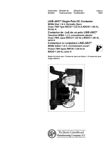
INTRODUCTION
Model
Gas
Tungsten-Arc
Welding
Current
Raiges
Rated
Welding
Current
100%
Duty
Cycle
At40
Volts
Open-
Circuit
Voltage
Rated
Input
At
Rated
Load
50/60
Hz
Single-Phase
~~5
~
kw
Overall
Dimensions
(Inches)
Weight
(Pounds)
T~J~T
~F~Tj
Volts
Volts
kva
300
Amperes
A.
18-320
Amperes
B.
24-425
Amperes
300
Amperes
Idling
-0
Start-80
Operate
-
165
166
83
38.2
20.5
Height-
56-1/2
Width
-27-1/4
Depth
-
38
1310
1380
500
Amperes
A.
25-320
Amperes
B.
70-670
Amperes
500
amperes
Idling
-0
Start
-80
Operate
-
165
284
142
65.4
29.7
Height-
57-3/8
Width
-
27-1/4
Depth
-
46
2235
2435
Fi~jre
2-1.
Specifications
This
manual
has
been
prepared
especially
for
use
in
familiar
izing
personnel
with
the
design,
installation,
operation,
main
tenance,
and
troubleshooting
of
this
equipment.
All
informa
tion
presented
herein
should
be
given
careful
consideration
to
assure
optimum
performance
of
this
equipment.
Prior
to
installing
this
equipment,
clean
all
packing
material
from
around
the
unit
and
carefully
inspect
for
any
damage
that
may
have
occurred
during
shipment.
Any
claims
for
loss
or
damage
that
may
have
occurred
in
transit
must
be
filed
by
the
purchaser
with
the
carrier.
A
copy
of
the
bill
of
lading
and
freight
bill
will
be
furnished
by
the
carrier
on
request
if
occasion
to
file
claim
arises.
When
requesting
information
concerning
this
equipment,
it
is
essential
that
Model
Description
and/or
Stock
Number
and
Serial
(or
Style)
Numbers
of
the
equipment
be
supplied.
This
unit
is
a
single-phase
welding
power
source
which
pro
duces
ac
welding
current.
This
unit
is
designed
to
be
used
as
the
welding
power
source
for
the
AC
Gas
Tungsten-Arc
(TIG)
Welding
process.
Before
the
equipment
is
put
into
operation,
the
safety
sec
tion
at
the
front
of
this
manual
should
be
read
completely.
This
will
help
avoid
possible
injury
due
to
misuse
or
improper
welding
applications.
The
following
definitions
apply
to
CAUTION,
IMPORTANT,
and
NOTE
blocks
found
throughout
this
manual:
~I~~U1l.]~IIIIl
Under
this
heading,
installation,
operating,
and
main
tenance
procedures
or
practices
will
be
found
that
if
not
carefully
followed
may
create
a
safety
hazard
to
personnel.
~1rj
Under
this
heading,
installation,
operating,
and
main
tenance
procedures
or
practices
will
be
found
that
if
not
carefully
followed
may
result
in
damage
to
equip
ment.
NOTE
Under
this
heading,
explanatory
statements
will
be
found
that
need
special
emphasis
to
obtain
the
most
efficient
operation
of
the
equipment.
SECTION
3
-
INSTALLATION
3-1.
LOCATION
(Figure
3-1)
Figure
3-1.
Dimensional
Drawing
TB.900
302.2
A
proper
installation
site
should
be
selected
for
the
welding
power
source
if
the
unit
is
to
provide
dependable
service,
and
remain
relatively
maintenance
free.
A
proper
installation
site
permits
freedom
of
air
movement
into
and
out
of
the
welding
power
source,
and
also
least
subjects
the
Unit
to
dust,
dirt,
moisture,
and
corrosive
vapors.
A
minimum
of
18
inches
of
unrestricted
space
must
be
main
tained
between
the
welding
power
source
front
and
rear
panels
and
the
nearest
obstruction.
Also,the
underside
of
the
welding
power
source
must
be
kept
completely
free
of
obstructions.
The
installation
site
should
also
permit
easy
removal
of
the
welding
power
source
outer
enclosure
for
maintenance
functions.
place
anjiig
over
the
in
ta
ke
air
pas~ges
of
the
welding
power
source
as
this
would
restrict
the
volume
of
intake
air
and
thereby
subject
the
welding
power
source
internal
components
to
an
overheating
condition
and
subsequent
failure.
War
ranty
is
void
if
any
type
of
filtering
device
is
used
2-1.
GENERAL
2-2.
RECEIVING-HANDLING
2-3.
DESCRIPTION
U
2-4.
SAFETY
I
I
I
I
I
500
Ampere
Model
Only
OM-162
Page
5

Holes
are
provided
in
the
welding
power
source
base
for
mounting
purposes.
Figure
3-1
gives
overall
dimensions
and
the
base
mounting
hole
layout.
On
most
welding
power
sources
a
lifting
device
is
provided
for
moving
the
unit.
However,
if
a
fork
lift
vehicle
is
used
for
lifting
the
unit,
be
sure
that
the
lift
forks
are
long
enough
to
extend
completely
under
the
base.
IMPORTANT
The
use
of
lift
forks
too
short
to
extend
Out
of
the
opposite
side
of
the
base
will
expose
internal
com
ponents
to
damage
should
the
tips
of
the
lift
forks
penetrate
the
bottom
of
the
unit.
3-2.
ELECTRICAL
INPUT
CONNECTIONS
ENOTE
-
I
It
is
recommended
that
a
Line
Disconnect
Switch
be
installed
in
the
input
Circuit
tO
the
welding
power
source.
This
would
provide
a
safe
and
convenient
means
to
completely
remove
all
electrical
power
from
the
welding
power
source
whenever
it
is
necessary
to
perform
any
internal
function
on
the
unit
CAUTION
Before
making
electrical
input
conons
to
the
welding
power
source,
machinery
lockout
proce
dures
should
be
employed.
If
the
connection
is
to
be
made
from
a
line
disconnect
switch,
the switch
should
be
padlocked
in
the
open
position.
If
the
connection
is
made
from
a
fuse
box,
remove
the
fuses
from
the
box
and
padlock
the
cover
in
the
closed
position.
If
lock
ing
facilities
are
not
available,
attach
a
red
tag
to
the
line
disconnect
switch
(or
fuse
box)
to
warn
others
that
the
circuit
is
being
worked
on.
A.
Input
Electrical
Requirements
This
welding
power
source
is
designed
to
be
operated
from
a
single-phase,
60
Hertz,
ac
power
supply
which
has
a
line
volt
age
rating
that
corresponds
with
one
of
the
primary
voltages
shown
on
the
welding
power
source
nameplate.
Consult
the
local
electric
utility
if
there
is
any
question
about
the
type
of
electrical
system
available
at
the
installation
site
or
how
pro.
per
connections
to
the
welding
power
source
are
to
be
made.
B.
Input
Conductor
Connections
IIIr~uII.]~IIuIJ
Do
not
connect
the
input
conductors
to
the
single.
I
phase
power
supply
until
all
input
electrical
connec
._
have
been
made
to
the
welding
power
source
The
input
conductors
should
be
covered
with
an
insulating
material
which
conforms
to
local
electrical
standards.
Table
3-1
is
provided
only
as
a
guide
for
selecting
the
proper
size
input
conductors
and
fuses.
Table
3.1.
Input
Conductor
and
Fuse
Size
Input
Conductor
(AWGI
Fuse
Size
(Amperes)
Mode)
208V
230V
460V
575V
208V
230V
460V
575Vj
300
3/0
2/0
4
6
Ampere
(4)
(6)
(8)
(8)
300
250
125
100
500
350
MCM
300
MCM
1/0
2
500
450
225
175
Ampere
(1/0)
(2)
(6)
(8)
IMumbers
in
I
I
indicate
ground
conductor
size.
Insert
the
two
input
conductors
plus
one
ground
conductor
through
the
access
hole
on
the
rear
panel.
The
hole
will
accept
standard
conduit
fittings.
See
Figure
3-2
for
hole
loca
tion
and
size.
reco
mmended
t
hat
a
t
erm
inal
lug
of
adeq
uate
amperage
capacity
be
attached
to
the
ends
of
the
input
and
ground
conductors.
The
hole
diameter
in
the
terminal
lug
must
be
of
proper
size
to
accommo~
date
the
line
and
ground
terminal
studs
on
the
primar~
terminal
board.
Connect
the
two
input
conductors
to
the
terminals
on
the
primary
terminal
board
labeled
L
or
LINE
and
connect
the
ground
conductor
to
the
terminal
labeled
GRD
(See
Figure
3-2).
The
remaining
end
of
the
ground
conductor
should
be
connected
to
a
proper
ground.
Use
whatever
grounding
method
that
is
acceptable
to
the
local
electrical
inspection
authority.
~rmi~I
labeled
C
)
is
connect~he
welding
power
source
chassis
and
is
for
grounding
purposes
only.
Do
not
connect
a
conductor
from
the
terminal
labeled
GRD
to
any
one
of
the
L
or
LINE
terminals
as
this
will
result
in
an
electrically
hot
welding
power
~source
chassis.
I
In
put
Voltage
Label
In
put
Voltage
Jumper
Links
TA-900
302-3
Figure
3-2.
Input
Conductor
Connections
C.
Matching
The
Welding
Power
Source
To
The
Avail
able
Input
Voltage
The
input
voltage
jumper
links
provided
on
the
primary
ter
minal
board
permit
the
welding
power
source
to
be
operated
from
various
line
voltages.
The
various
voltages
from
which
this
welding
power
source
may
be
operated
are
stated
on
the
welding
power
source
nameplate,
and
on
the
input
voltage
label.
See
Figure
3-2
for
location.
The
input
voltage
jumper
links
on
this
welding
power
source
are
positioned
for
the
highest
of
the
voltages
stated
on
the
nameplate.
If
the
weld
ing
power
source
is
to
be
operated
from
a
line
voltage
which
is
lower
than
the
highest
voltage
for
which
the
unit
was
de
signed,
the
jumper
links
will
have
to
be
moved
to
the
proper
position
before
operation
of
the
welding
power
source
com
mences.
Figure
3-3
shows
the
various
positions
for
which
the
jumper
links
may
be
set
on
the
standard
welding
power
source.
If
the
input
voltages
on
the
welding
power
source
nameplate
differ
from
those
shown
in
Figure
3-3,
the
input
voltage
jumper
links
must
be
positioned
as
shown
on
the
in
put
voltage
label.
NOTE
J
If
only
one
jumper
link
is
required
on
each
of
the
grouped
terminals,
it
is
recommended
that
the
unused
jumper
links
be
placed
across
the
terminals
which
are
to
be
used.
This
will
prevent
losing
the
lumper
links
i
which
are
not
required
for
this
connection
Line
Terminals
Page
6

230
VOLTS
460
VOLTS
~
0
U~L~~i
'
'n1~
GRD
I
J~U,3LII
012
425
Figure
3-3.
Input
Voltage
Jumper
Link
Arrangement
3-3.
SECONDARY
CONNECTIONS
It
is
recommended
that
the
welding
cables
be
kept
as
short
as
possible,
placed
close
together
and
be
of
adequate
Current
carrying
capacity.
The
resistance
of
the
welding
cables
and
connections
cause
a
voltage
drop
which
is
added
to
the
volt
age
of
the
arc.
Excessive
cable
resistance
may
result
in
over
loading
as
well
as
reducing
the
maximum
current
output
of
which
the
welding
power
source
is
capable.
The
proper
opera
tion
of
any
arc
welding
power
source
is
to
a
great
extent
dependent
on
the
use
of
welding
cables
and
connections
that
are
in
good
condition
and
of
adequate
size.
An
insulated
electrode
holder
must
be
used
to
ensure
the
operators
safety.
Use
Table
3-2
as
a
guide
for
selecting
the
correct
welding
cable
size
for
the
anticipated
maximum
weld
current
that
will
be
used.
Table
3-2
takes
into
account
the
total
length
of
cable
for
the
weld
circuit.
This
means
the
length
of
the
Elec
trode
cable
that
connects
the
Electrode
Holder
to
the
weld
ing
power
source
and
the
Work
or
ground
cable
between
the
welding
power
source
and
the
work
piece.
For
example:
If
the
Electrode
cable
is
75
feet
long
and
the
work
or
ground
cable
is
25
feet
long,
select
the
size
cable
froni
Table
3-2
that
is
recommended
for
100
feet
at
the
maximum
amperage
that
will
be
used.
In
the
case
of
a
maximum
anticipated
weld
current
of
300
amperes,
2/0
weld
cable
would
be
recom
mended
for
both
the
Electrode
and
Work
cables.
Table
3-2.
Secondary
Cable
Sizes
WELDING
TOTA
LLEN
GTH
OF
CABLE
ICOPPE
RHN
WELD
CI
RCUIT
AMPERES
50
100
150
200
250
300
350
400
100
4
4
2
2 2
1
1/0
1/0
150
2
2
2
1
1/0
2/0
3/0 3/0
200
1
1
1
1/0
2/0
3/0
4/0
4/0
250
1/0
1/0
1/0
2/0
3/0
4/0
4/0
2-2/0
300
2/0
2/0
2/0
3/0
4/0
4/0
2-2/0
2.3/0
350
3/0
3/0
2/0
4/0
4/0
2-2/0
2-3/0
2-3/0
400
3/0
3/0
3/0
4/0
2-2/0
2-3/0
3-2/0
2-4/0
500
4/0
4/0
4/0
22/0
2-3/0
2-3/0
2-4/0
3-3/0
600
22/0
2-2/0
2-2/0
2-3/0
3-2/0
2-4/0
3-3/0
3-4/0
A-002 623
NOTE:
A.
50
FEET
OR
LESS.
8.
CABLE
SIZE
IS
BASED
ON
DIRECT
CURRENT
bC).
100%
DUTY
CYCLE
AND
EITHER
A
4
VOLTS
OR
LESS
DROP
OR
A
CURRENT
DENSITY
OF
NOT
OVER
300
CIRCULAR
MILS
PER
AMP.
C.
WELD
CABLE
INSULATION
WITH
A
VOLTAGE
RATING
TO
WITHSTAND
THE
OPEN-CIRCUIT
VOLT
AGE
(OCVI
OF
THE
WELDING
POWER
SOURCE
MUST
BE
USED.
WHILE
MOST
WELDING
POWER
SOURCES
HAVE
AN
OPEN-CIRCUIT
VOLTAGE
OF
LESS
THAN
100
VOLTS.
SOME
WELDING
POWER
SOURCES
OF
SPECIAL
DESIGN
MAY
HAVE
HIGHER
OPEN-CIRCUIT
VOLTAGE.
3-4.
REMOTE
AMPERAGE
CONTROL
CONNECTIONS
(Figure
4-1)
The
REMOTE
AMPERAGE
CONTROL
Receptacle
provides
a
junction
point
for
connecting
a
Remote
Amperage
Control
to
the
amperage
control
circuitry
in
the
welding
power
source.
To
connect
the
Remote
Amperage
Control
to
the
REMOTE
AMPERAGE
CONTROL
Receptacle,
insert
the
three-pole
plug
from
the
Remote
Amperage
Control
into
the
receptacle
and
rotate
the
plug
as
far
as
it
will
turn
in
a
clockwise
direc
tion.
Once
fully
rotated,
the
plug
will
be
locked
In
the
recep
tacle
and
will
not
pull
Out
under
stress.
3-5.
CONTACTOR
CONTROL
CONNECTIONS
(Figure
4-1)
The
CONTACTOR
CONTROL
Receptacle
provides
a
junc
tion
point
for
connecting
a
Remote
Contactor
Control
device
to
the
contactor
control
circuitry
in
the
weldIng
power
Source.
To
connect
the
Remote
Contactor
Control
to
the
CONTAC
TOR
CONTROL
Receptacle,
insert
the
plug
from
the
Re
mote
Contactor
Control
device
into
the
CONTACTOR
CON
TROL
Receptacle
and
rotate
the
plug
as
far
as
it
will
turn
in
a
clockwise
direction.
The
plug
will
now
be
locked
in
the
receptacle
and
will
not
pull
out
under
stress.
3-6.
WATER
VALVE
CONNECTIONS
(Figure
4-1)
A
valve
is
provided
in
order
to
control
on
and
off
flow
of
coolant
water
to
the
electrode
holder.
The
WATER
valve
input
and
output
connections
both
have
left-hand
threading.
Ensure
that
the
hose
from
the
water
source
is
attached
to
the
connection
on
the
WATER
valve
labeled
IN.
The
water
hose
from
the
electrode
holder
must
be
attached
to
the
connec
tion
on
the
WATER
valve labeled
OUT.
an
t
Pu
mp
iri~ii
th
e
C
oolant
P
U
rnp
is
not
equipped
with
a
by-pses
network,
do
not
make
connections
from
the
Coolant
Pump
to
the
WATER
valve
but
rather
connect
the
Coolant
Pump
directly
to
the
electrode
holder
water
hoses.
Failure
to
comply
may
result
in
damage
to
the
Coolant
Pump
due
to
excessive
back
pressure
when
the
WATER
valve
is
closed.
3-
7.
SHIELDING
GAS
VALVE
CONNECTIONS
(Figure
4-1)
A
valve
is
provided
in
order
to
control
on
and
off
flow
of
shielding
gas
to
the
electrode
holder.
The
GAS
valve
input
and
output
connections
both
have
right-hand
threading.
En
eire
that
the
hose
from
the
shielding
gas
source
is
attached
to
the
connection
on
the
GAS
valve
labeled
IN.
The
shielding
gas
hose
from
the
electrode
holder
must
be attached
to
the
connection
on
the
GAS
valve
labeled
OUT.
3-8.
EXTERNAL-INTERNAL
HIGH
FREQUENCY
SELECTION
(Figure
4-1)
A
six-pole
terminal
strip
{7T)
with
two
jumper
links
attached
is
supplied
in
order
to
provide
selection
of either
the
welding
power
source
high
frequency
unit
for
operation
or
anexter
nal
high
frequency
unit
for
operation.
Placing
the
two
jumper
links
on
the
High
Frequency
Terminal
Strip
in
the
INTER
NAL
position
will
permit
operation
of
the
high
frequency
unit
within
the
welding
power
source.
Placing
the
jumper
links
in
the
EXTERNAL
position
will
provide
a
115
volts
ac
signal
to
the
extreme
left
and
right
terminals
of
the
High
Fre
quency
Terminal
Strip
for
operation
of
an
external
high
fre
quency
unit.
The
two
control
leads
from
the
external
high
frequency
unit
must
be
connected
to
the
extreme
left
and
right
terminals
of
terminal
strip
7T
in
order
to
receive
the
llSvoIts
acsignal.
(
0
1
t~i~LhJh3Lt1
GRD
1
I
OM-162
Page
7

te
rnal
high
f
requency
is
to
be
U
sed,
e
n
su
re
that
the
control
circuitry
in
the
high
frequency
unit
is
of the
type
that
requires
115
volts
ac
for
operation.
Also,
the
duration
of
the
115
volts
ac
signal
being
fed
to
the
external
high
frequency
unit
by
way
of
the
High
Frequency
Terminal
Strip,
will
be
govemed
by
the
position
of
the
HIGH
FREQUENCY
Switch
on
the
welding
power
source.
I
I
3-9.
AUTOMATIC-MANUAL
TERMINAL
STRIP
(Figure
4-1)
A
four-pole
terminal
strip
with
one
jumper
link
attached
is
provided
in
order
to
determine
whether
80
or
165
open-
circuit
volts
will
be
available.
When
the
jumper
link
on
the
AUTOMATIC-MANUAL
Terminal
Strip
is
placed
in
the
MANUAL
position,
80
open-circuit
volts
will
be
available.
When
the
jumper
link
is
placed
in
the
AUTOMATIC
position,
165
open-circuit
volts
will
be
available
for
40
cycles.
Whenever
a
hand-held
electrode
holder
is
to
be
used,
the
AUTOMATIC-MANUAL
jumper
link
must
be
in
the
MANUAL
position.
3-10.
EXTERNAL
START
SWITCH
CONNECTIONS
(Fig
u
re
4-1)
A
six-pole
terminal
strip
(8T),
with
two
jumper
links
attach
ed,
is
provided
in
order
to
determine
whether
high
frequency
and
open-circuit
voltage
will
be
present
at
the
secondary
terminals
as
soon
as
the
Remote
Contactor
Control
Switch
is
closed
or
whether
high
frequency
and
165
volts
open-circuit
voltage
will
be
present
when
the
External
Start
Switch
applies
a
momentary
115
volts
ac
signal.
Whenever
a
hand-held
electrode
holder
or
a
fixed
automatic
electrode
holder
is
to
be
used,
the
jumper
links
on
the
Elec
trode
Holder
Control
Terminal
Strip
must
be
in
the
INTER
NAL
position.
When
in
the
INTERNAL
position,
open-
circuit
voltage
and
high
frequency
will
be
present
at
the
elec
trode
as
soon
as
the
Remote
Contactor
Control
is
closed.
Whenever
a
retractable
automatic
electrode
holder
is
to
be
used,
the
jumper
links
on
the
Electrode
Holder
Control
Terminal
Strip
must
be
in
the
EXTERNAL
position.
When
in
the
EXTERNAL
position,
the
115
volts
signal
leads
from
the
welding
head
must
be
connected
to
the
outermost
terminals
of
the
Electrode
Holder
Control
Terminal
Strip.
As
soon
as
the
Remote
Contactor
Control
is
closed,
when
in
the
EXTERNAL
position,
80
open-circuit
volts
without
high
frequency
will
be
present
at
the
secondary
terminals.
As
soon
as
the
welding
head
supplies
a
115
volts
ac
signal
to
the
Electrode
Holder
Control
terminal
strip,
165
open-circuit
volts
with
high
frequency
will
be
present
at
the
secondary
terminals.
If
an
arc
is
not
established
in
40
cycles
(2/3
second),
the
high
frequency
will
shutoff
and
the
open-circuit
voltage
will
revert
to
80
volts.
In
order
to
restart
the
arc,
it
will
be
necessary
to
open
the
Remote
Contactor
Control
and
once
again
close
the
Remote
Contactor
Control
and
also
apply
the
115
volts
ac
signal
to
the
Electrode
Holder
Control
Terminal
strip.
SECTION
4-FUNCTION
OF
CONTROLS
TC.900
302.4
I
I
Adjustment
Control
Start
Adjustment
Control
Range
Switch
Remote
Amperage
Control
Switch
Con
tactor
Control
Receptacle.
High
Frequency
Delay
Timer
Electrode
Holder
Control
Terminal
Strip
Power
Switch
High
Frequency
Switch
High
Frequency
Intensity
Control
Electrode
Terminal
\
Coolant
Shielding
Gas
Valve
Valve
Figure
4-1.
Control
Location

4-
1.
POWER
SWITCH
(Figure
4-1)
4-5.
START
ADJUSTMENT
(Figure
4-1)
The
Start
Adjustment
facility
in
this
welding
power
source
permits
the
operator
to
select
an
amperage
setting
for
arc
initiation
which
is
different
from
the
setting
of
the
AMPERAGE
ADJUSTMENT
Control.
The
starting
current
which
is
selected
will
be
in
effect
for
the
first
35
to4O
cycles
of
the
weld.
After
this
time
period,
the
weld
current
will
go
to
the
setting
of
the
AMPERAGE
ADJUSTMENT
Control.
A.
Start
Control
Terminal
Strip
The
jumper
link
and
three
terminals
of
terminal
strip
lOT
are
provided
to
select
whether
the
START
ADJUSTMENT
Con
trol
will
be
operative
or
inoperative.
Placing
the
jumper
link
associated
with
these
three
terminals
in
the
IN
position
will
make
the
START
ADJUSTMENT
Control
on
the
front
panel
operative.
Placing
the
jumper
link
in
the
OUT
position
will
make
the
START
ADJUSTMENT
Control
inoperative
and
thereby
cause
the
weld
current
to
go
immediately
to
the
setting
of
the
AMPERAGE
ADJUSTMENT
Control
upon
arc
initiation.
B.
Stan
Adjustment
Control
The
START
ADJUSTMENT
Control
provides
fine
amperage
selection
within
the
minimum
to
maximum
capabilities
of
the
range
being
used
for
the
initial
35
to
40
cycles
(approxi
mately
2/3
of
a
second)
time
period
of
the
weld.
After
this
initial
time
period,
the
weld
current
will
either
slope
up
or
down
to
the
setting
of the
AMPERAGE
ADJUSTMENT
Con
trol.
4-
6.
HIGH-FREQUENCY
SWITCH
(Figure
4-1)
The
HIGH-FREQUENCY
Switch,
located
on
the
upper
front
panel,
provided
three
positions
which
will
determine
whether
the
high
frequency
will
be
on
or
off.
A.
Stan
Position
When
in
the
START
position,
high
frequency
will
be
present
at
the
welding
electrode
until
the
arc
is
initiated.
Once
an
arc
is
established,
and
even
though
the
Remote
Contactor
Con
trol
Switch
is
closed,
the
high
frequency
will
be
de-energized.
High
frequency
will
be
present
again
only
after
the
arc
is
broken and
restarted.
B.
Continuous
Position
The
CONTINUOUS
position
will
provide
high
frequency
for
as
long
as
the
Remote
Contactor
Control
Switch
is
closed.
The
high
frequency
and
weld
current
may
be
shut
off
during
the
weld
by
releasing
the
Remote
Con
tactor
Control
Switch.
C.
Off
Position
High
frequency
will
not
be
available
when
in
the
OFF
posi
tion,
even
if
the
contactor
is
energized.
This
position
must
be
used
when
performing
Shielded
Metal-Arc
Welding
(Stick
Electrode).
CAUTION
Never
try
to
use
high
frequency
when
performing
Shielded
Metal-Arc
Welding
IStick
Electrode).
Failure
to
comply
may
result
in
the
high
frequency
arcing
through
the
electrode
holder
and
seriously
injuring
the
operator.
4-7.
HIGH-FREQUENCY
INTENSITY
CONTROL
(Figure
4-1)
NOTE
As
the
high-frequency
intensity
is
increased,
the
possi
bility
of
causing
interference
with
local
radio
and
tele
vision
receivers
also
increases,
It
is
recommended
that
the
High-Frequency
Intensity
Control
be
set
at
as
low
a
position
as
possible
in
order
to
avoid
receiver
inter
ference.
Placing
the
POWER
Switch
in
the
ON
position
will
energize
the
welding
power
source
fan
and
control
circuitry
and
place
the
welding
power
source
in
a
ready-to-weld
status.
Placing
the
POWER
Switch
in
the
OFF
position
will
shut
the
welding
power
source
down.
1awiuiir.i~u1J
Even
though
the
POWER
Switch
is
in
the
OFF
posi
tion
and
the
welding
power
source
is
apparently
elec
trically
shut
down,
electrical
input
power
is
still
pre
sent
on
all
circuitry
up
to
the
POWER
Switch.
To
completely
cut
-
off
all
electrical
input
power
to
the
welding
power
source,
it
will
be
necessary
to
place
the
line
disconnect
switch
in
the
OFF
position
or
remove
the
electrical
input
circuit
fuses.
4-2.
RANGE
SWITCH
(Figure
4-1)
The
Range
Switch
provides
the
capability
of
selecting
from
four
coarse
amperage
ranges.
The
amperage
range
of
each
switch
position
is
displayed
on
the
welding
power
source
nameplate.
In
addition
to
selecting
the
coarse
amperage
range,
the
Range
Switch
will
also
determine
whether
or
not
the
capacitor
balance
circuitry
will
be
operative.
When
one
of
the
two
ranges
are
selected
which
have
the
labeling
IN,
the
capacitor
balance
circuitry
will
be
operative.
When
either
of
the
ranges
with
the
OUT
labeling
are
selected,
the
capacitor
balance
circuitry
will
be
inoperative.
4-3.
AMPERAGE
ADJUSTMENT
CONTROL
(Figure
4-1)
The
AMPERAGE
ADJUSTMENT
Control,
located
on
the
upper
center
portion
of
the
front
panel,
provides
a
means
of
selecting
the
exact
amperage
desired
within
the
range
being
used.
Rotating
the
control
in
a
clockwise
direction
will
in
crease
the
amperage
output.
LNOTE
I
I
I
The
contacts
of
the
AMPERAGE
ADJUSTMENT
Con
trol
are
of
the
continuous
contact
type,
thereby
making
it
possible
to
adjust
the
amperage
output
while
welding.
I
I
The
scale
surrounding
the
AMPERAGE
ADJUSTMENT
Con
trol
is
calibrated
in
percentage
and
should
not
be
miscon
strued
as
an
amperage
or
voltage
reading,
4-4.
REMOTE
AMPERAGE
CONTROL
RECEPTACLE
&
SWITCH
(Figure
4-1)
If
a
Remote
Amperage
Control
is
to
be
used,
make
connec
tions
from
the
Remote
Amperage
Control
to
the
REMOTE
AMPERAGE
CONTROL
Receptacle
as
instructed
in
item
3-4.
When
remote
control
of
the
amperage
is
desired,
it
is
essential
that
the
REMOTE
AMPERAGE
CONTROL
Switch
be
placed
in
the
REMOTE
position.
Likewise,
if
a
Remote
Amperage
Control
is
not
to
be
utilized,
the
switch
must
be
in
the
STANDARD
position,
When
in
the
STANDARD
position,
only
the
AMPERAGE
ADJUSTMENT
Control
on
the
front
panel
will
control
the
amperage.
When
a
Remote
Amperage
Control
is
being
used,
it
should
be
noted
that
the
Remote
Amperage
Control
is
functioning
as
a
fine
amperage
adjustment
for
the
AMPERAGE
ADJUST
MENT
Control
setting
on
the
welding
power
source.
For
example:
If
the
AMPERAGE
ADJUSTMENT
Control
on
the
welding
power
source
is
set
at
the
mid-range
position,
the
Remote
Amperage
Control
will
provide
(from
the
mm.
to
max.
positions)
fine
amperage
adjustment
of
one
half
of
the
welding
power
source
output
for
the
current
range
selected
by
means
of
the
Range
Switch.
If
full
adjustment
thru
use
of
the
Remote
Amperage
Control
of
the
current
range
selected
is
desired,
the
AMPERAGE
ADJUSTMENT
Control
on
the
welding
power
source
must
be
set
at
the
maximum
position.
I
I
I
OM-162
Page
9

A
High-Frequency
Intensity
Control
is
provided
on
the
lower
front
panel
for
controlling
the
strength
of
the
high
fre
quency.
Rotating
the
control
in
a
clockwise
direction
will
increase
the
intensity
of
the
high
frequency.
4-
8.
HIGH
FREQUENCY
DELAY
TIMER
(Figure
4-1)
A
0
to
3
second
timer
is
provided
on
the
lower
front
panel
for
varying
the
time
period
between
contactor
and
subse
quent
high-frequency
energization.
To
select
the
desired
portion
of
the
maximum
3
second
time
period
available,
rotate
the
adjustable
stop
arm
on
the
timer
until
the
appropriate
setting
is
obtained.
As
soon
as
the
contactor
is
energized,
the
High-Frequency
Delay
Timer
Will
begin
to
count
down
the
preset
time.
As
soon
as
the
present
time
on
the
High
Frequency
Delay
Timer
has
elapsed,
high
frequency
will
be
present
as
determined
by
the
HIGH-FREQUENCY
Switch.
4-9.
CONTACTOR
CONTROL
RECEPTACLE
(Figure
4.1)
The
contactor
control
circuitry
in
this
welding
power
source
provides
a
means
of
making
weld
output
available
whenever
desired
without
having
to
position
the
POWER
Switch
ON
or
OFF.
If
a
Remote
Contactor
Control
device
is
to
be
used,
make
connections
to
the
REMOTE
CONTACTOR
CONTROL
Receptacle
as
instructed
in
item
3-5.
The
Remote
Contactor
Control
device
will,
when
closed,
energize
the
contactor
and
gas
and
water
valves.
When
the
Remote
Contactor
Control
device
is
opened,
the
contactor
will
open
and
suspend
the
weld
output;
also
the
Post-Flow
Timer
will
energize
and
begin
to
time
out.
4-10.
POST-FLOW
TIMER
(Figure
4-1)
An
adjustable
0
to
60
second
Post-Flow
Timer
is
provided
for
controlling
the
period
of
time
shielding
g~
and
water
(coolant)
will
be
allowed
to
flow
after
the
arc
is
extinguished.
To
select
the
desired
portion
of
the
maximum
60
second
post-flow
time
period
available,
rotate
the
adjustable
stop
arm
on
the
timer
until
the
appropriate
setting
is
obtained,
As
soon
as
the
arc
has
been
extinguished,
the
Post-Flow
Timer
will
begin
to
time
out
the
selected
period
of
post-flow
time.
Once
the
selected
post-flow
time
has
elapsed,
the
gas
and
water
valve
will
close
and
thereby
cut
off
shielding
gas
and
water
flow.
The
timer
will
then
automatically
reset
and
be
ready
for
another
weld
cycle.
4-11.
DUTY
CYCLE
(Figure
4-2)
The
duty
cycle
of
the
welding
power
source
is
the
percentage
of
a
ten
minute
period
that
a
welding
power
source
can
safely
be
operated
at
a
given
output
current
setting.
This
welding
power
source
is
rated
at
300
or
500
amperes
(depending
on
model),
100
percent
duty
cycle.
This
means
the
welding
power
source
can
be
safely
operated
at
300
or
500
amperes
(depending
on
model)
welding
current
continuously.
If
the
welding
current
is
increased,
the
duty
cycle
will
decrease.
Figure
4-2
enables
the
operator
to
determine
the
safe
output
of
the
welding
power
source
at
various
duty
cycles.
Figure
4-2.
Duty
Cycle
Chart
IMPORTANT
Exceeding
the
indicated
duty
cycle
will
cause
the
welding
power
source
to
overheat,
thereby
causing
damage
to
the
welding
power
source.
4-12.
VOLT-AMPERE
CURVE
(Figure
4-3)
The
volt-ampere
curve
shows
the
output
voltage
available
at
any
given
output
current
within
the
limits
of
the
minimum
and
maximum
AMPERAGE
ADJUSTMENT
Control
setting.
Load
voltage
is
predetermined
to
a
large
degree
by
arc
characteristics.
With
the
use
of
the
volt-ampere
curve,
it
is
possible
to
determine
the
amperage
required
for
a
specific
load
voltage.
With
reference
to
the
volt-ampere
curve
(Figure
4-3),
the
curve
shows
only
the
maximum
and
minimum
settings
of
the
AMPERAGE
ADJUSTMENT
Control
foreach
of
the
welding
current
ranges
available.
Curves
of
other
settings
will
fall
between
the
maximum
and
minimum
curves
shown.
-Jo.
34
10
1~
20
25
30
40
50
eo
ioeoeoioo
%
DUTY
CYCLE
A-101
446
*
300
Ampere
Model
A-101
491
200
300
400
300
0
C.
0~ERES
500
Ampere
Model
Figure
4-3.
Volt-Ampere
Curves
A-Wi
490
Page
10

Link
In
Manual
Position
S3
In
HF
Start
Position
Close
Start
Switch
(Remote
Contactor
Control
RC2)
CR3
Closes
H
Make
Ready
Provides
80V
GS1
And
For
H.F.
Open
Circuit
WS1
Open
CR1
Ready
For
Safety
Over
Voltage
HF
ON
HF
Arc
Established
CR6
Closes
On
Normal
Arc
Voltage
CR7
Closes.
Delays
Contactor
Drop
Out
If
Arc
Lost
W
Closes
CR11p.u.
Wi
Opens
CR12
Remains
Closed
CR13
Remains
Open
Start
Rheostat
Operative
WELDING
ARC
ESTABLISHED
CR11
d.o.
CR12
do.
After
Time
Delay
CR13
p.u-Main
Rheostat
Operative
CR5
Closes
Make
Ready
Make
Ready
For
Closing
To
Close
Bypass
And
Contactor
W
HF
Through
CR2
1
TD3
Opens
After
Time
Delay
CR2
Times
Out
High
Frequency
CR8
Opens
Bypass
After
Delay
Figure
4-4.
Normal
Weld
Flow
Chart
Intentional
Arc
Outage
With
Start
Switch
Closed
(Manual
Position
Only)
CR1
Opens
Circuit
to
CR7
CR7
Times
Out
Contactor
Reverts
to
80
V.O.C.
And
HF
CR5
Opens
CR4
Open
CR2 CR6
w
C
pens
WS1
Times
Out
Opens
Opens
CR4
Closes
No
Function
On
Manual
Make
Ready
For
CR6
165
Volts
Effective
Voltage
Applied
To
Welding
Load
CR1
Closes
On
Excessive
Rise
In
Arc
Voltage
CR2
Closes
I-IF
Bypass
CR8
Closes
To
Give
HF
Ready
For
Intentional
Welding
Arc
CR11
p.u.
CR12
p.u.
CR13
d.o.
Start
Rheostat
Operative
WELDING
ARC
RE-ESTABLISHED
CR1
Opens
CR11
d.o.
CR2
Times
Out
HF
CR12d.o.
After
Time
Delay
I
I
CR8
Opens
Bypass
CR13
p.u.
Main
Rheostat
Operative
Normal
Welding
Arc
Intentional
Arc
Outage
By
Opening
Start
Switch
(RC2)
CR3
Ooens
80
V.
Circuit
GS1
Times
Out
No
Open
Circuit
Voltage
No
High
Frequency
Wi
Closes
CR12
p.u.
CR
13
do.
Start
Rheostat
Operative
Figure
4-5.
Arc
Outage
Flow
Chart
No
Open
Circuit
Voltage
No
HF
TB-900
302.5
OM-162
Pa~
11

SECTION
5
P.
AINTENANCE
!
Ensure
that
the
branch
circuit
or
main
disconnect
switch
is
open
or
electrical
input
circuit
fuses
are
removed
before
attempting
any
inspection
or
work
on
the
inside
of
the
welding
power
source.
Placing
the
welding
power
source
POWER
Switch
in
the
OFF
position
does
not
remove
voltage
from
the
power
terminals
inside
the
welding
power
source.
NOTE
Cleaning
or
dressing
the
points
of
the
spark
gaps
is
not
recommended,
as
the
material
at
the
points
is
tungsten
and
is
impossible
to
file,
The
entire
point
should
be
replaced
when
the
tungsten
section
is
completely
disappeared.
To
Adjust
Spark
Gaps,
Proceed
As
Follows:
5-1.
RECTIFIER
It
is
recommended
that
the
rectifier
be
cleaned
occasionally
by
blowing
it
out
with
compressed
air.
This
cleaning
opera
tion
is
necessary
so
that
maximum
cooling
will
be
accom
plished
by
the
air
stream.
This
should
be
done
periodically
depending
upon
the
location
of
the
unit
and
the
amount
of
dust
and
dirt
in
the
atmosphere.
52.
FAN
MOTOR
All
models
are
equipped
with
an
exhaust
fan
and
rely
on
forced
draft
for
adequate
cooling
for
high
duty
cycles
and
overloads.
The
fan
motor
is
manufactured
with
lifetime
lubricated
sealed
ball
bearings
and
no
attention
should
be
required.
5-
3.
TRANSFORMER
Occasional
blowing
out
of
the
dust
and
dirt
from
around
the
transformer
is
recommended.
This
should
be
done
period
ically
depending
upon
the
location
of the
unit
and
the
amount
of
dust
and
dirt
in
the
atmosphere.
The
welding
power
source
case
cover
should
be
removed
and
a
clean
dry
air
stream
should
be
used
for
this
cleaning
operation.
5.4.
SPARK
GAP
The
spark
gaps
can
be
readily
inspected
by
opening
the
access
door
on
the
front
of
the
welding
power
source.
The
spark
gaps
are
normally
set
at
.008
clearance
at
the
factory.
It
will
be
necessary
to
periodically
readjust
these
after
extended
operation.
Usually
inspection
and
adjustment
every
three
or
four
months
will
suffice.
Readjustment
is
also
indicated
when
intermittent
operation
of
the
gaps
is
noted.
Usually
this
occurs
when
thesetting
has
increased
to
.013
or
greater.
Generally
speaking,
the
high
frequency
output
varies
directly
(up
to
a
certain
point)
with
the
spark
gap
spacing.
In
extreme
cases
where
the
greatest
amount
of
high
frequency
is
needed,
it
may
be
necessary
to
adjust
the
spark
gap
setting
to
.010
or
even
.013.
This
also
increases
the
high
frequency
radia
tion
and
it
is
suggested
that
the
minimum
gap
setting
(.004
to
.008),
consistent
with
good
welding
operation,
be
used.
1.
Loosen
screw
A
on
both
sides.
2.
Place
feeler
gauge
of
proper
thickness
between
gaps
C.
3.
Apply
slight
pressure
against
point
B
so
feeler
gauge
is
held
firmly
in
gap.
4.
Tighten
screws
A.
Figure
5-1.
Spark
Gap
Adjustment
SECTION
6
-
TROUBLESHOOTING
The
data
collected
here,
discusses
some
of
the
common
problems
which
may
occur
in
this
welding
power
source.
The
assumption
of
this
data
is
that
a
proper
welding
condition
has
been
achieved
and
has
been used
until
trouble
developed.
In
all
cases
of
equipment
malfunction,
the
manufacturers
recommendations
should
be
strictly
adhered
to
and
followed,
If
after
performing
the
following
procedures
the
trouble
is
still
not
remedied,
it
is
recommended
that
a
serviceman
be
called,
It
is
recommended
that
the
circuit
diagram
be
used
for
reference
during
troubleshooting.
TROUBLE
PROBABLE
CAUSE
REMEDY
No
welding
output.
Open
line
fuse.
Replace
line
fuse,
if
open.
POWER
Switch
defective.
Replace
POWER
switch,
if
defec
tive.
No
welding
output.
Fuse
(Fl)
open.
Replace
fuse
(Fl),
if
open.
Fuse
)F4)
open.
Replace
fuse
)f4),
if
open.
I
I
I
U
I
I
TA-020
623-A
2
Page
12

Erratic
weld
current.
Loose
welding
connections.
Secure
connections.
Bad
or
damp
electrodes.
Use
new
dry
electrodes.
Fan
does
not
run.
POWER
Switch
defective.
Replace
POWER
switch,
if
defec.
tive.
Fan
motor
defective.
Replace
fan
motor,
if
defective.
Line
fuse
open.
Replace
line
fuse,
if
open.
Welding
current
low.
AMPERAGE
ADJUSTMENT
Control
does
not
control
current.
Low
line
voltage.
Use
correct
line
voltage.
Use
of
welding
cable
which
is
too
long
or
too
small
for
weld-
ing
current
employed.
Use
proper
size
cable.
Loose
connections
to
work
or
loose
welding
cable
connections.
Secure
connections.
Fuse
F3
open.
Replace
fuse
(F3).
if
open.
Welding
current
low.
AMPERAGE
ADJUSTMENT
Control
does
not
control
current.
Fuse
(F2)
open.
Replace
fuse
(F2).
if
open.
Tungsten
electrode
oxidizing
a~d
not
remaining
bright
after
conclu
sion
of
weld.
Loose
gas
fittings
on
regulator
of
gas
line.
Secure
gas
fittings.
Insufficient
gas
flow.
Increase
gas
flow.
Drafts
blowing
gas
shield
away
from
tungsten.
Shield
welding
arc
area.
Wandering
Arc,
poor
control
of
direction
of
arc.
Tungsten
being
used
considerably
larger
than
recommended.
Use
proper
size
tungsten.
Lack
of
High
Frequency,
difficul.
ty
in
establishing
the
arc.
Spark
gap
incorrect.
Adjust
spark
gap
(See
item
5-4).
Tungsten
larger
then
recommended
for
weld
current
involved.
Use
proper
size
tungsten.
Leakage
of
high
frequency
from
electrode
holder
cable.
Replace
electrode
holder.
Figure
6-1.
Circuit
Diagram
For
300
Ampere
Model
Circuit
Diagram
No.
CC-900
302-iC
L~1s
OM-162
Page
13

METERS
OPTIONAL
26
44
~
47
53
27
5750
76
0
0
0000000
hO
2
4
S I
~J722
23
2436
0000
0000000000
55
01
4
26
127
36
~
42473352
0000
00000000
01
3334
00
Circuit
Diagram
No.
CC-900
311-1C1
Figure
6-2.
Circuit
Diagram
For
500
Ampere
Model
SEE
IF~5TRUCTION
R000
FOR
PROPER
PRIMARY
CONNECTIONS
h202
47535036
000000000
I,
520
5,0
~
001
500
0
Page
14
Page is loading ...
Page is loading ...
Page is loading ...
Page is loading ...
Page is loading ...
Page is loading ...
Page is loading ...
Page is loading ...
Page is loading ...
Page is loading ...
Page is loading ...
Page is loading ...
Page is loading ...
Page is loading ...
/