
Table of Contents
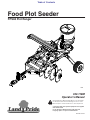
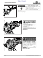
Cover photo may show optional equipment not supplied
with standard unit.
For an Operator’s Manual and Decal Kit in French
Language, please see your Land Pride dealer.
Read the Operator’s Manual entirely. When you see this symbol,
the subsequent instructions and warnings are serious - follow
without exception. Your life and the lives of others depend on it!
!
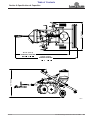
Food Plot Seeder
FPS48 Plot Ranger
322-118M
Operator’s Manual
Printed 12/7/18
23896

12/7/18FPS48 Plot Ranger Food Plot Seeder 322-118M
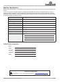
Machine Identification
Record your machine details in the log below. If you replace this manual, be sure to transfer this information to the new
manual.
If you, or the dealer, have added Options not originally ordered with the machine, or removed Options that were
originally ordered, the weights and measurements are no longer accurate for your machine. Update the record by
adding the machine weight and measurements provided in the Specifications & Capacities Section of this manual with
the Option(s) weight and measurements.
Dealer Contact Information
Model Number
Serial Number
Machine Height
Machine Length
Machine Width
Machine Weight
Delivery Date
First Operation
Accessories
Name:
Street:
City/State:
Telephone:
Email:
WARNING: Cancer and reproductive harm - www.P65Warnings.ca.gov
!
California Proposition 65

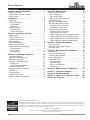
Table of Contents
12/7/18
© Copyright 2018 All rights Reserved
Land Pride provides this publication “as is” without warranty of any kind, either expressed or implied. While every precaution has been taken in the
preparation of this manual, Land Pride assumes no responsibility for errors or omissions. Neither is any liability assumed for damages resulting from the use
of the information contained herein. Land Pride reserves the right to revise and improve its products as it sees fit. This publication describes the state of this
product at the time of its publication, and may not reflect the product in the future.
Land Pride is a registered trademark.
All other brands and product names are trademarks or registered trademarks of their respective holders.
Printed in the United States of America.
FPS48 Plot Ranger Food Plot Seeder 322-118M
Table of Contents
Important Safety Information . . . . . . . . . . . . . 1
Safety at All Times . . . . . . . . . . . . . . . . . . . . . . . . . 1
Look for the Safety Alert Symbol . . . . . . . . . . . . . . . 1
Safety Labels . . . . . . . . . . . . . . . . . . . . . . . . . . . . . 4
Introduction . . . . . . . . . . . . . . . . . . . . . . . . . . . 6
Application . . . . . . . . . . . . . . . . . . . . . . . . . . . . . . . 6
Using This Manual . . . . . . . . . . . . . . . . . . . . . . . . . 6
Terminology . . . . . . . . . . . . . . . . . . . . . . . . . . . . . 6
Definitions . . . . . . . . . . . . . . . . . . . . . . . . . . . . . . 6
Owner Assistance . . . . . . . . . . . . . . . . . . . . . . . . . . 6
Serial Number . . . . . . . . . . . . . . . . . . . . . . . . . . . 6
Further Assistance . . . . . . . . . . . . . . . . . . . . . . . . 6
Section 1: Assembly & Set-up . . . . . . . . . . . . 7
Requirements . . . . . . . . . . . . . . . . . . . . . . . . . . . . . 7
Dealer Preparations . . . . . . . . . . . . . . . . . . . . . . . . 7
Torque Requirements . . . . . . . . . . . . . . . . . . . . . . . 7
Hitch Assembly . . . . . . . . . . . . . . . . . . . . . . . . . . . . 8
Rear Axle Assembly . . . . . . . . . . . . . . . . . . . . . . . . 8
Ratchet Jack Assembly . . . . . . . . . . . . . . . . . . . . . . 8
Optional Equipment Assembly . . . . . . . . . . . . . . . . 9
Linear Actuator . . . . . . . . . . . . . . . . . . . . . . . . . . 9
Rear Packer . . . . . . . . . . . . . . . . . . . . . . . . . . . . . 9
Spin Spreader . . . . . . . . . . . . . . . . . . . . . . . . . . 10
Section 2: Operating Procedures . . . . . . . . . 12
Operating Checklist . . . . . . . . . . . . . . . . . . . . . . . . 12
Operator’s Responsibilities . . . . . . . . . . . . . . . . . . 12
Hook-up Plot Ranger . . . . . . . . . . . . . . . . . . . . . . . 12
Raising & Lowering the Unit . . . . . . . . . . . . . . . . . 13
Ratchet Jack . . . . . . . . . . . . . . . . . . . . . . . . . . . 13
Linear Actuator (Optional) . . . . . . . . . . . . . . . . . 13
Transport Plot Ranger . . . . . . . . . . . . . . . . . . . . . . 13
Calibrating the Spin Controller . . . . . . . . . . . . . . . 14
Field Set-up . . . . . . . . . . . . . . . . . . . . . . . . . . . . . . 14
Field Operation . . . . . . . . . . . . . . . . . . . . . . . . . . . 15
Unhook Plot Ranger . . . . . . . . . . . . . . . . . . . . . . . 15
General Operating Instructions . . . . . . . . . . . . . . . 16
Section 3: Adjustments . . . . . . . . . . . . . . . . . 17
Disc Gang Adjustments . . . . . . . . . . . . . . . . . . . . . 17
Disc Gang Angle . . . . . . . . . . . . . . . . . . . . . . . . 17
Disc Gang Position . . . . . . . . . . . . . . . . . . . . . . . 17
Disc Blade Replacement1vb . . . . . . . . . . . . . . . 17
Level Disc Harrow . . . . . . . . . . . . . . . . . . . . . . . . . 18
Spin Spreader Adjustments . . . . . . . . . . . . . . . . . . 18
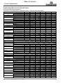
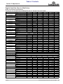
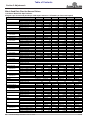
Spin Spreader Rates (English . . . . . . . . . . . . . . . . 19
Narrow Pattern Calculations . . . . . . . . . . . . . . . . 19
Wide Pattern Calculations . . . . . . . . . . . . . . . . . 19
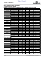
Spin Spreader Rates (Metric . . . . . . . . . . . . . . . . . 19
Narrow Pattern Calculations . . . . . . . . . . . . . . . . 19
Wide Pattern Calculations . . . . . . . . . . . . . . . . . 19
English Seed Rate Chart for Narrow Pattern . . . 20
English Seed Rate Chart for Wide Pattern . . . . . 21
Metric Seed Rate Chart for Narrow Pattern . . . . 22
Metric Seed Rate Chart for Wide Pattern . . . . . . 23
Section 4: Optional Equipment . . . . . . . . . . . 24
Linear Actuator . . . . . . . . . . . . . . . . . . . . . . . . . . . 24
Spin Spreader and Rear Packer . . . . . . . . . . . . . . 24
Extension Tube . . . . . . . . . . . . . . . . . . . . . . . . . . . 24
Section 5: Maintenance & Lubrication . . . . . 25
Maintenance . . . . . . . . . . . . . . . . . . . . . . . . . . . . . 25
Daily Operational Checks . . . . . . . . . . . . . . . . . . . 25
Clean the Spin Spreader . . . . . . . . . . . . . . . . . . . . 25
Long-Term Storage . . . . . . . . . . . . . . . . . . . . . . . . 26
Lubrication Points . . . . . . . . . . . . . . . . . . . . . . . . . 27
Rear Axle Tube . . . . . . . . . . . . . . . . . . . . . . . . . 27
Wheel Bearings . . . . . . . . . . . . . . . . . . . . . . . . . 27
Rear Packer Bearings . . . . . . . . . . . . . . . . . . . . 27
Ratchet Jack . . . . . . . . . . . . . . . . . . . . . . . . . . . 27
Section 6: Specifications & Capacities . . . . . 28
Section 7: Features & Benefits . . . . . . . . . . . 30
Section 8: Troubleshooting . . . . . . . . . . . . . . 31
Section 9: Torque & Tire Inflation Charts . . .32
Section 10: Warranty . . . . . . . . . . . . . . . . . . . 33

Table of Contents Continued
12/7/18
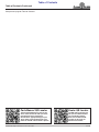
Parts Manual QR Locator
The QR (Quick Reference) code on the
cover and to the left will take you to the
Parts Manual for this equipment.
Download the appropriate App on your
smart phone, open the App, point your
phone on the QR code and take a picture.
Dealer QR Locator
The QR code on the left will
link you to available dealers
for Land Pride products.
Refer to Parts Manual QR
Locator on this page for
detailed instructions.
FPS48 Plot Ranger Food Plot Seeder 322-118M
Table of Contents
See previous page for Table of Contents.

Important Safety Information
12/7/18
1
Important Safety Information
Listed below are common practices that may or may not be applicable to the products
described in this manual.
Safety at All Times
Careful operation is your best
assurance against an accident.
All operators, no matter how much
experience they may have, should
carefully read this manual and
other related manuals, or have the
manuals read to them, before
operating the power machine and
this implement.
Thoroughly read and understand
the “Safety Label” section. Read
all instructions noted on them.
Do not operate the equipment
while under the influence of drugs
or alcohol as they impair the ability
to safely and properly operate the
equipment.
The operator should be familiar
with all functions of the tractor and
attached implement and be able to
handle emergencies quickly.
Make sure all guards and shields
appropriate for the operation are in
place and secured before
operating implement.
Keep all bystanders away from
equipment and work area.
Start tractor from the driver’s seat
with hydraulic controls in neutral.
Operate tractor/skid steer and
controls from the driver’s seat only.
Never dismount from a moving
tractor or leave tractor unattended
with engine running.
Do not allow anyone to stand
between tractor and implement
while backing up to implement.
Keep hands, feet, and clothing
away from power-driven parts.
While transporting and operating
equipment, watch out for objects
overhead and along side such as
fences, trees, buildings, wires, etc.
Do not turn tractor so tight as to
cause hitched implement to ride
up on the tractor’s rear wheel.
Store implement in an area where
children normally do not play.
When needed, secure implement
against falling with support blocks.
Look for the Safety Alert Symbol
The SAFETY ALERT SYMBOL indicates there is a
potential hazard to personal safety involved and extra
safety precaution must be taken. When you see this
symbol, be alert and carefully read the message that
follows it. In addition to design and configuration of
equipment, hazard control, and accident prevention are
dependent upon the awareness, concern, prudence, and
proper training of personnel involved in the operation,
transport, maintenance, and storage of equipment.
Tractor Shutdown & Storage
If engaged, disengage power
take-off.
Park on solid, level ground and
lower implement to ground or onto
support blocks.
Put tractor in park or set park
brake, turn off engine, and remove
switch key to prevent unauthorized
starting.
Relieve all hydraulic pressure to
auxiliary hydraulic lines.
Wait for all components to stop
before leaving operator’s seat.
Use steps, grab-handles and
anti-slip surfaces when stepping
on and off the tractor.
Detach and store implement in an
area where children normally do
not play. Secure implement using
blocks and supports.
OFF
REMOVE
Safety Precautions for
Children
Tragedy can occur if the operator
is not alert to the presence of
children. Children generally are
attracted to implements and their
work.
Never assume children will remain
where you last saw them.
Keep children out of the work area
and under the watchful eye of a
responsible adult.
Be alert and shut the implement
and tractor down if children enter
the work area.
Never carry children on the tractor
or implement. There is not a safe
place for them to ride. They may
fall off and be run over or interfere
with the control of the power
machine.
Never allow children to operate the
power machine, even under adult
supervision.
Never allow children to play on the
power machine or implement.
Use extra caution when backing
up. Before the tractor starts to
move, look down and behind to
make sure the area is clear.
Be Aware of
Signal Words
A signal word designates a degree or
level of hazard seriousness. The
signal words are:
Indicates a hazardous situation that, if
not avoided, will result in death or
serious injury.
Indicates a hazardous situation that, if
not avoided, could result in death or
serious injury.
Indicates a hazardous situation that, if
not avoided, may result in minor or
moderate injury.
WARNING
CAUTION
!
!
!
DANGER
!

Important Safety Information
12/7/18
2
Listed below are common practices that may or may not be applicable to the products
described in this manual.
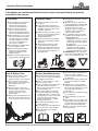
Transport Safely
Comply with federal, state, and
local laws.
Use towing vehicle and trailer of
adequate size and capacity. Secure
equipment towed on a trailer with
tie downs and chains.
Sudden braking can cause a towed
trailer to swerve and upset. Reduce
speed if towed trailer is not
equipped with brakes.
Avoid contact with any overhead
utility lines or electrically charged
conductors.
Always drive with load on end of
loader arms low to the ground.
Always drive straight up and down
steep inclines with heavy end of a
tractor with loader attachment on
the “uphill” side.
Engage park brake when stopped
on an incline.
Maximum transport speed for an
attached equipment is 20 mph. DO
NOT EXCEED. Never travel at a
speed which does not allow
adequate control of steering and
stopping. Some rough terrains
require a slower speed.
As a guideline, use the following
maximum speed weight ratios for
attached equipment:
20 mph when weight of attached
equipment is less than or equal
to the weight of machine towing
the equipment.
10 mph when weight of attached
equipment exceeds weight of
machine towing equipment but
not more than double the weight.
IMPORTANT: Do not tow a load
that is more than double the weight
of the vehicle towing the load.
Practice Safe Maintenance
Understand procedure before doing
work. Refer to the Operator’s Manual
for additional information.
Work on a level surface in a clean
dry area that is well-lit.
Lower implement to the ground and
follow all shutdown procedures
before leaving the operator’s seat to
perform maintenance.
Do not work under any hydraulic
supported equipment. It can settle,
suddenly leak down, or be lowered
accidentally. If it is necessary to work
under the equipment, securely
support it with stands or suitable
blocking beforehand.
Use properly grounded electrical
outlets and tools.
Use correct tools and equipment for
the job that are in good condition.
Allow equipment to cool before
working on it.
Disconnect battery ground cable (-)
before servicing or adjusting
electrical systems or before welding
on equipment.
Inspect all parts. Make certain parts
are in good condition & installed
properly.
Replace parts on this implement
with genuine Land Pride parts only.
Do not alter this implement in a way
which will adversely affect its
performance.
Do not grease or oil implement while
it is in operation.
Remove buildup of grease, oil, or
debris.
Always make sure any material and
waste products from the repair and
maintenance of the implement are
properly collected and disposed.
Remove all tools and unused parts
before operation.
Tire Safety
Tire changing can be dangerous
and must be performed by
trained personnel using the
correct tools and equipment.
Always maintain correct tire
pressure. Do not inflate tires
above recommended pressures
shown in the Operator’s Manual.
When inflating tires, use a clip-on
chuck and extension hose long
enough to allow you to stand to
one side and NOT in front of or
over the tire assembly. Use a
safety cage if available.
Securely support the implement
when changing a wheel.
When removing and installing
wheels, use wheel handling
equipment adequate for the
weight involved.
Make sure wheel bolts have been
tightened to the specified torque.
Use A Safety Chain
A safety chain will help control
drawn machinery should it
separate from the tractor drawbar.
Use a chain with the strength
rating equal to or greater than the
gross weight of the towed
implement.
Attach the chain to the tractor
drawbar support or other specified
anchor location. Allow only
enough slack in the chain to
permit turning.
Always hitch the implement to the
machine towing it. Do not use the
safety chain to tow the implement.

Important Safety Information
12/7/18
3
Listed below are common practices that may or may not be applicable to the products
described in this manual.
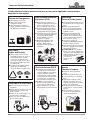
Avoid High
Pressure Fluids Hazard
Escaping fluid under pressure can
penetrate the skin causing serious
injury.
Relieve all residual pressure
before disconnecting hydraulic
lines or performing work on the
hydraulic system.
Make sure all hydraulic fluid
connections are tight and all
hydraulic hoses and lines are in
good condition before applying
pressure to the system.
Use a piece of paper or
cardboard, NOT BODY PARTS, to
check for suspected leaks.
Wear protective gloves and safety
glasses or goggles when working
with hydraulic systems.
DO NOT DELAY. If an accident
occurs, see a doctor familiar with
this type of injury immediately. Any
fluid injected into the skin or eyes
must be treated within
a few hours or
gangrene may
result.
Wear Personal Protective
Equipment (PPE)
Wear protective clothing and
equipment appropriate for the job
such as safety shoes, safety
glasses, hard hat, and ear plugs.
Clothing should fit snug without
fringes and pull strings to avoid
entanglement with moving parts.
Prolonged exposure to loud noise
can cause hearing impairment or
hearing loss. Wear suitable
hearing protection such as
earmuffs or earplugs.
Operating equipment safely
requires the operator’s full
attention. Avoid wearing
headphones while operating
equipment.
Use Safety
Lights and Devices
Slow moving tractors and self-
propelled machines can create a
hazard when driven on public
roads. They are difficult to see,
especially at night. Use the Slow
Moving Vehicle (SMV) sign when
on public roads.
Flashing warning lights and turn
signals are recommended
whenever driving on public roads.
Prepare for Emergencies
Be prepared if a fire starts.
Keep a first aid kit and fire
extinguisher handy.
Keep emergency numbers for
doctor, ambulance, hospital, and
fire department near phone.
911
Keep Riders Off Machinery
Never carry riders on tractor or
implement.
Riders obstruct operator’s view and
interfere with the control of the
power machine.
Riders can be struck by objects or
thrown from the equipment.
Never use tractor or implement to
lift or transport riders.
Handle
Chemicals Properly
Protective clothing should be
worn.
Handle all chemicals with care.
Follow instructions on container
label.
Agricultural chemicals can be
dangerous. Improper use can
seriously injure persons, animals,
plants, soil, and property.
Inhaling smoke from any type of
chemical fire is a serious health
hazard.
Store or dispose of unused
chemicals as specified by the
chemical manufacturer.
Use Seat Belt and ROPS
Land Pride recommends the use
of a CAB or roll-over-protective-
structures (ROPS) and seat belt
in almost all power machines.
Combination of a CAB or ROPS
and seat belt will reduce the risk
of serious injury or death if the
power machine should be upset.
If ROPS is in the locked-up
position, fasten seat belt snugly
and securely to help protect
against serious injury or death
from falling and machine overturn.

Important Safety Information
FPS48 Plot Ranger Food Plot Seeder 322-118M 12/7/18
4
Table of Contents
23904
Safety Labels
Your Plot Ranger comes equipped with all safety labels in
place. They were designed to help you safely operate your
implement. Read and follow their directions.
1. Keep all safety labels clean and legible.
2. Refer to this section for proper label placement. Replace
all damaged or missing labels. Order new labels from your
nearest Land Pride dealer. To find your nearest dealer,
visit our dealer locator at www.landpride.com.
3. Some new equipment installed during repair requires
safety labels to be affixed to the replaced component as
specified by Land Pride. When ordering new components
make sure the correct safety labels are included in the
request.
4. Refer to this section for proper label placement.
To install new labels:
a. Clean surface area where label is to be placed.
b. Spray soapy water onto the cleaned area.
c. Peel backing from label and press label firmly onto the
surface.
d. Squeeze out air bubbles with edge of a credit card or
with a similar type of straight edge.
858-095C
2" x 4 1/2" Red Reflector (2 places)
Important Safety Information


Introduction
FPS48 Plot Ranger Food Plot Seeder 322-118M 12/7/18
6
Table of Contents
Owner Assistance
The dealer should complete the Online Warranty
Registration at the time of purchase. This information is
necessary to provide you with quality customer service.
The parts on your food plot seeder have been specially
designed by Land Pride and should only be replaced with
genuine Land Pride parts. Contact a Land Pride dealer if
customer service or repair parts are required. Your Land
Pride dealer has trained personnel, repair parts, and
equipment needed to service the implement.
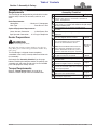
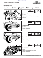
Serial Number
For quick reference and prompt service, record model
and serial number on the inside cover page and again on
the warranty page. Always provide model number and
serial number when ordering parts and in all
correspondences with your Land Pride dealer. For
location of your serial number plate, see Figure 1.
Serial Number Plate Location
Figure 1
Further Assistance
Your dealer wants you to be satisfied with your new Plot
Ranger. If for any reason you do not understand any part
of this manual or are not satisfied with the service
received, the following actions are suggested:
1. Discuss any problems you have with your implement
with your dealership service personnel so they can
address the problem.
2. If you are still not satisfied, seek out the owner or
general manager of the dealership, explain the
question/problem, and request assistance.
3. For further assistance write to:
Land Pride Service Department
1525 East North Street
P.O. Box 5060
Salina, Ks. 67402-5060
E-mail address
lpser[email protected]
NOTE: A special point of information that the
operator should be aware of before continuing.
23905
Introduction
Land Pride welcomes you to the growing family of new
product owners. This Plot Ranger has been designed
with care and built by skilled workers using quality
materials. Proper assembly, maintenance, and safe
operating practices will help you get years of satisfactory
use from this machine.
Application
The Land Pride Plot Ranger is a highly versatile full
component package designed to open and break up soil
surfaces by discing the soil for seedbed or planting
preparation. It will then spread the seed while
simultaneously pressing the seeds into the soil with a
trailing fluted roller/packer. It can then be used to spread
fertilizer, lime, gypsum, and other soil conditioning
amendments at distances ranging from 4 ft. to 20 ft. The
combination spin spreader/planter portion of this system
can also be used in the off-season to spread sand or salt
for winter icing or slick snow conditions.
The Plot Ranger is a pull type implement designed to be
pulled behind smaller compact utility tractors, off road
utility vehicles, and ATVs. This system can be easily
raised out of working position and up onto transport
wheels either manually or with a 12 volt linear actuator.
The combination of maximum versatility and narrow
transport width makes the Plot Ranger an excellent
choice for applications in wild game food plots, hunting
clubs, hunting resorts, ranches, farms, game preserves,
landscaping, hobby farming, smaller nurseries, and
gardens.
See “Specifications & Capacities” on page 28 and
“Features & Benefits” on page 30 for additional
information and performance enhancing options.
Using This Manual
•
This Operator’s Manual is designed to help familiarize
you with safety, assembly, operation, adjustments,
troubleshooting, and maintenance. Read this manual
and follow the recommendations to help ensure safe
and efficient operation.
• The information contained within this manual was
current at the time of printing. Some parts may change
slightly to assure you of the best performance.
• To order a new Operator’s or Parts Manual, contact
your authorized dealer. Manuals can also be
downloaded, free-of-charge, from our website at
www.landpride.com
Terminology
“Right” or “Left” as used in this manual is determined by
facing the direction the machine will operate while in use
unless otherwise stated.
Definitions
IMPORTANT: A special point of information related
to the following topic. Land Pride’s intention is this
information must be read & noted before continuing.

Section 1: Assembly & Set-up
FPS48 Plot Ranger Food Plot Seeder 322-118M12/7/18
7
Table of Contents
Requirements
The Plot Ranger is designed to be pulled behind smaller
compact utility tractors, off road utility vehicles, and
ATVs.
Basic Requirements:
Horsepower . . . . . . . . . . . . . Minimum 17 horsepower
Hitch Type . . . . . . . . . . . . . . . . . . Draw Bar or 2" Ball
Optional Equipment Requirements:
Linear Actuator Connection . . . . . 12 Volt Battery Post
Spin Spreader Connection . 12 V. Plug-in Receptacle
Dealer Preparations
WARNING
!
To avoid serious injury or death:
Be careful when working with disc blades as the edges are
sharp. Wear gloves when working around disc blades. Keep
others away.
This Plot Ranger is shipped almost completely
assembled at the factory. Carefully follow instructions for
final assembly.
Go through the “Assembly Checklist” on this page
before assembling the food plot seeder. To speed up your
assembly task and make the job safer, have all needed
parts and equipment readily at hand.
Torque Requirements
Refer to “Torque Values Chart” on page 32 to
determine correct torque values for common bolts.
Assembly Checklist
Check Page
Make sure miscellaneous assembly tools are on hand:
Hammer, tape measure, assortment of wrenches &
sockets, and spirit level.
Have a forklift or hoist with properly sized chains and
safety stands on hand
that are sized for the job ready
for the assembly task
.
Have a minimum of two people available during
assembly.
Make sure loose parts bag/box is shipped with the
implement.
Make sure all major components and loose
parts are shipped with the machine.
Operator’s
Manual
Double check to make sure all fasteners &
pins are installed in the correct location.
Refer to the Parts Manual if unsure.
NOTE: All assembled hardware from the
factory has been installed in the correct
location. Remember location of a part or
fastener if removed. Keep parts separated.
Operator’s
Manual
Make sure working parts move freely, bolts
are tight & cotter pins are spread.
Operator’s
Manual
Make sure all grease fittings are in place
and lubricated.
Page 27
Make sure all safety labels are correctly
located and legible. Replace if damaged.
Page 4
Make sure all red and amber reflectors are
correctly located and visible when machine
is in transport position.
Page 4
Make sure all wheel bolts and axle nuts are
tightened to the specified torque.
Page 32
Make sure all tires are inflated to the
specified psi air pressure.
Page 32
Section 1: Assembly & Set-up

Section 1: Assembly & Set-up
FPS48 Plot Ranger Food Plot Seeder 322-118M 12/7/18
8
Table of Contents
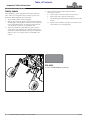
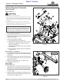
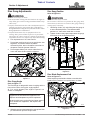
Ratchet Jack Assembly
Figure 1-1
Hitch Assembly
Refer to Figure 1-1:
Refer to Torque Values Chart on page 32 for proper
torque values when tightening nuts.
1. Attach front hitch frame (#3) to the disc frame with
four 3/4" -10 x 1 3/4" GR5 hex head cap screws (#7)
and 3/4" hex flange locknuts (#9). Tighten nuts to
correct torque.
2. Position hitch assembly (#4), depending upon which
will be used, with either the 2" ball or the clevis facing
foreword.
3. Attach hitch assembly (#4) to front hitch frame (#3)
with two 5/8"-11 x 3 1/2" GR5 hex head cap
screws (#6) and hex flange locknuts (#10). Tighten
nuts to correct torque.
Rear Axle Assembly
Refer to Figure 1-1:
Refer to Torque Values Chart on page 32 for proper
torque values when tightening nuts.
1. Position rear axle assembly (#2) under the disc
frame with rear axle adjusting lug (A) oriented as
shown.
2. Attach rear axle assembly (#2) with 1/2"-13 x 3" GR5
hex head cap screws (#5), half clamps (#1), and
1/2" hex flange locknuts (#8). Tighten nuts (#8) to
40 ft-lbs. of torque.
NOTE: The ball or clevis hitch may require
repositioning after the Plot Ranger is attached to a
small utility tractor, utility vehicle, or ATV.
See “Level Disc Harrow” on page 18 for a detailed
description of repositioning the hitch.
IMPORTANT: Deformation of tube will occur if
1/2" hex flange locknuts (#8) are torqued more than
40 ft. lbs.
Ratchet Jack Assembly
Refer to Figure 1-1:
The Plot Ranger is shipped with a Ratchet Jack (#13) or
an optional Linear Actuator will be packaged separate if
purchased with the unit. See “Linear Actuator” on
page 9 if one is included.
1. Remove hair pin cotters (#11) and 1" x 3 3/16" clevis
pins (#12) from both ends of the ratchet jack.
2. Attach lower end of ratchet jack to the front mounting
lug (B) as shown with clevis pin (#12) and secure it
with hair pin cotter (#11).
3. Operate ratchet jack handle (#C) to move the upper
clevis until it aligns with the rear axle adjusting lug
hole (A).
4. Attach upper end of ratchet jack to the rear axle
adjusting lug (A) as shown with clevis pin (#12) and
secure it with hair pin cotter (#11).

Section 1: Assembly & Set-up
FPS48 Plot Ranger Food Plot Seeder 322-118M12/7/18
9
Table of Contents
Optional Equipment Assembly
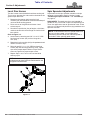
Linear Actuator
Refer to Figure 1-2:
CAUTION
!
To avoid minor or moderate injury:
• Make sure electrical wiring is supported in such a way that
it will not make contact with trash, lift mechanism, rotating
discs, pinch points, vehicle rotating components, vehicle hot
exhaust, etc.
• Extending and retracting actuator creates pinch point
hazards. Keep fingers, hands, and all extremities clear of all
moving parts when operating toggle switch (G).
1. Remove one of two hair pin clips (#2) from both hitch
pins (#3). Remove hitch pins.
2. Attach lower end of linear actuator (#3) to the front
mounting lug (B) with hitch pin (#2). Secure in place
with hair pin clip (#1).
3. Install hand controller as follows:
a. Plug connector (E) into connector (F).
b. Wrap electrical wiring around one of the tie down
straps and along the hitch frame as shown in
Figure 1-5 on page 11.
c. Attach black wire alligator clip (C) to the negative
(-) battery post.
d. Attach white wire alligator clip (D) to the positive
(+) battery post.
Refer to Figure 1-5 on page 11:
4. Operate toggle switch (G) to move upper clevis end
of actuator until it aligns with the rear axle adjusting
lug hole (A).
5. Attach upper end of Linear Actuator (#3) to the rear
axle adjusting lug hole with hitch pin (#2) and secure
with hair pin clip (#1).
6. Remove hand controller (#4) and store in a dry
location until ready to use.
Rear Packer
Refer to Figure 1-3:
1. Attach rear packer frame (#2) to disc frame (#1) as
shown with 1/2"-13 x 1 GR5 cap screws (#3) and hex
flange locknut (#4). Draw locknut up snug and then
back-off 1/4 turn. Roller frame should pivot about the
1/2" bolts freely.
2. Lower disc harrow to the ground and by lifting at the
handle, rotate rear packer (#2) up over the disc frame
until it rest on its supports (#A).
NOTE: Ties (#5) may be used to secure electrical
wiring. If ties are used, attach them loosely or out of
material that can be removed easily to allow easy
removal of electrical components for dry storage.
Linear Actuator Assembly (Optional)
Figure 1-2
Rear Roller Assembly
Figure 1-3
23907
23908
Lift Handles

Section 1: Assembly & Set-up
FPS48 Plot Ranger Food Plot Seeder 322-118M 12/7/18
10
Table of Contents
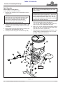
Spin Spreader Assembly
Figure 1-4
23909
Mounting
Tabs
Spin Spreader
Refer to Figure 1-4 on page 10:
Install spreader assembly as follows:
1. Remove spin spreader and all component from the
shipping box.
2. (Optional) Install restrictor plate (#2) as shown on top
of existing nuts. Install stainless steel hex huts (#8)
and tighten.
3. Being careful not to damage the electrical wiring, drill
out pop rivet and remove wire clip (#6).
4. Insert spin motor wiring into the new wire clip (#6).
NOTE: The restrictor plate (#2) is used to restrict
product flow out of the two hopper openings. Some
applications will require removal of the restrictor
plate to allow a higher discharge rate. Other
applications will require the restrictor plate be
installed to decrease the discharge rate.
5. (Optional) Attach spin deflector (#3) and new wire
clip (#6) to the lower channel bracket with
1/4"-20 x 3/4" GR5 hex flange serrated screws (#7)
and wing nuts (#9). Hand tighten wing nuts.
6. Bolt 5 1/2" x 14 3/4" splash plate (#13) to the vertical
tube with #10-32 x 2" flat head machine screws (#15)
and nylock nuts (#14). Tighten nuts.
7. Slide spreader mounting bracket (G) into disc frame
support tube (H). Secure with 5/16" x 2 1/2" clevis
pin (#10) and hair pin cotter (#11).
NOTE: The spin deflector (#3) diverts seed to 48"
width. It can be installed depending on your seed
dispersal needs.
Installation Note: Spin deflector (#3) can be
installed without removing hopper (#11). Install spin
deflector (#3) by holding mounting tabs to the rear
and slide deflector between hopper (#11) and spin
plate (#12). Rotate deflector mounting tabs around to
the front to line up with side holes.

Section 1: Assembly & Set-up
FPS48 Plot Ranger Food Plot Seeder 322-118M12/7/18
11
Table of Contents
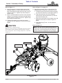
Refer to Figure 1-5:
8. Attach one end of a ratchet tie down strap to the
spreader eyebolt (F) and the other end to the front
hole (G) located on the left side of the disc frame as
shown in Figure 1-5. Tighten strap only enough to
remove slack.
9. Attach a second tie down strap to the same spreader
eyebolt (F) and to hole (H) located on the right side of
the disc frame as shown in Figure 1-5. Tighten strap
only enough to remove slack.
10. Tighten both tie down strap equally to prevent
spreader box from jiggling in its mount. Do not over
tighten.
CAUTION
!
To avoid minor or moderate injury:
Make sure electrical wiring is supported in such a way that it
will not make contact with trash, lift mechanism, rotating
discs, pinch points, vehicle rotating components, vehicle hot
exhaust, etc.
Plot Ranger Assembly
Figure 1-5
F
5
5
23916
Tie Down Straps
G
H
Wrap Electrical
Wiring As shown
Refer to Figure 1-4 on page 10:
11. Store hand controller (#12) in a dry location. The
following steps are required if installing at set-up:
a. Thread hand control wires with white connector
(A) and black connector (C) through eye bolt (F).
b. Plug white connector (A) into the feedgate
connector (B) and black connector (C) into the
spin motor connector (D).
c. Wrap wires around one of the tie down strap and
along the hitch frame as shown in Figure 1-5
below.
d. Plug lighter plug (E) into a 12 volt accessory
receptacle.
Refer to Figure 1-5:
NOTE: Ties (#5) may be used to secure electrical
wiring. If ties are used, attach them loosely or out of
material that can be removed easily to allow easy
removal of electrical components for dry storage.

Section 2: Operating Procedures
FPS48 Plot Ranger Food Plot Seeder 322-118M 12/7/18
12
Table of Contents
•
Do not stand or climb on the implement.
• Be careful when working with disc blades as the edges are
sharp. Wear gloves when working around disc blades. Keep
others away.
• Dress properly for the job. Do not wear loose fitting
clothing or clothing with pull strings. Keep long hair tucked
in. They can become entangled in rotating components.
Wear footwear that will improve footing on slippery
surfaces. Always be sure of your footing and keep a firm
hold on handles. Walk, never run.
• Select a safe ground speed when transporting. Never travel
at a speed which does not allow adequate control of steering
and stopping, and never exceed 20 mph (32.2 km/h) with
attached equipment. Rough terrain requires a slower speed.
• Make sure safety labels are in their proper location and are
in good condition before operating the attached implement.
Read and obey all instructions on the labels.
• Perform scheduled maintenance. Check for loose
hardware, missing parts, broken parts, structural cracks,
and excessive wear. Make repairs before putting implement
back into service. Serious breakdowns can result in injury
or death.
• The roller packer is heavy. It is best to lower the disc
harrow to the ground before rotating the roller packer down
or up over the seeder box.
• Always use the handle on the left side frame when rotating
the roller packer down or up. Never grab the packer by the
roller when raising and lowering.
• Do not alter implement or replace parts on the implement
with other brands. Other brands may not fit properly or
meet OEM (Original Equipment Manufacturer)
specifications. They can weaken the integrity and impair the
safety, function, performance, and life of the implement.
Replace parts only with genuine OEM parts.
CAUTION
!
To avoid minor or moderate injury:
Disconnect electrical power to the linear actuator and spin
spreader before working on or around the disc harrow and
spin spreader.
Hook-up Plot Ranger
DANGER
!
To avoid serious injury or death:
A crushing hazard exists while hooking-up and unhooking
implement. Keep people and animals away while backing-up
to implement or pulling away from implement. Do not operate
hydraulic or electrical controls while a person or animal is
directly behind the power machine or near the implement.
IMPORTANT: Never back up with roller packer on
the ground. Damage to the Plot Ranger could result.
Section 2: Operating Procedures
Operating Checklist
Hazard control and accident prevention are dependent
upon the awareness, concern, prudence, and proper
training involved in the operation, transport, storage, and
maintenance of the seeder. Therefore, It is absolutely
essential that no one operates the seeder unless they are
age 16 or older and have read, fully understood, and are
totally familiar with the Operator’s Manual. Make sure the
operator has paid particular attention to:
• Important Safety Information, page 1
• Section 1: Assembly & Set-up, page 7
• Section 2: Operating Procedures, page 12
• Section 3: Adjustments, page 17
• Section 4: Optional Equipment, page 24
• Section 5: Maintenance & Lubrication, page 25
Operator’s Responsibilities
DANGER
!
To avoid serious injury or death:
• Do not allow anyone near the vehicle or implement while
operating. Stop operation if bystanders are too close. They
can be hit by flying projectiles, become entangled in the
equipment, or ran over.
• Always secure equipment with solid, non-concrete supports
before working under it. Never go under equipment
supported by concrete blocks or hydraulics. Concrete can
break, hydraulic lines can burst, and/or hydraulic controls
can be actuated even when power to hydraulics is off.
WARNING
!
To avoid serious injury or death:
• Never make contact with underground utilities such as
electrical power lines, gas lines, phone lines, etc. They can
cause serious injury or death from electrocution, explosion,
or fire. If in doubt, call 811 (USA) before digging so that
they can mark the location of underground services in the
area. For contact information, see Dig Safe in the
“Important Safety Information” starting on page 1.
• Allow only persons to operate this implement who have
fully read and comprehended this manual, who have been
properly trained in the safe operation of this implement, and
who are age 16 or older. Serious injury or death can result
from the inability to read, understand, and follow
instructions provided in this manual.
• Never carry riders on the implement or power machine.
Riders can obstruct the operator’s view, interfere with
control of the equipment, be pinched by moving
components, become entangled in rotating components, be
struck by objects, be thrown or fall from the equipment, etc.
• Do not use implement for a purpose other than the work it
is designed to do as defined in this manual.
• Do not use implement as a man lift, work platform or as a
wagon to carry objects. It is not properly designed or
guarded for this use.

Section 2: Operating Procedures
FPS48 Plot Ranger Food Plot Seeder 322-118M12/7/18
13
Table of Contents
WARNING
!
To avoid serious injury or death:
The disc harrow tongue can have negative tongue weight that
may cause immediate elevation of tongue. Set gauge wheels 1"
above ground before hitching or unhitching from implement.
Store implement with gauge wheels touching the ground.
1. Back vehicle up to the Plot Ranger hitch until holes in
the drawbar and clevis are aligned or until the ball is
aligned with the ball hitch.
2. If gauge wheels are resting on the ground, operate
ratchet jack or linear actuator to raise the wheels off
the ground 1".
• For instructions on how to hook-up the linear
actuator, refer to step 4 for wiring.
• For instructions on how to operate the ratchet jack
or linear actuator, refer to “Raising & Lowering
the Unit” on page 13.
3. Attach hitch as follows:
• Clevis Type Hitch: Insert customer supplied pin
through the clevis and drawbar. Secure pin in place
with customer supplied keeper pin.
• 2" Ball Type Hitch: Drop hitch over 2" ball and rotate
latch lever down to secure the hitch to the ball. A
customer supplied pin may be inserted through the
hole in the latch to secure it in place.
CAUTION
!
To avoid minor or moderate injury:
Make sure electrical wiring is supported in such a way that it
will not make contact with trash, lift mechanism, rotating
discs, pinch points, vehicle rotating components, vehicle hot
exhaust, etc.
Refer to Figure 1-2 on page 9:
4. (Optional) Linear Actuator Electrical Hook-up:
a. Plug connector (E) into connector (F).
b. Wrap electrical wiring around one of the tie down
straps and along the hitch frame as shown in
Figure 1-5 on page 11.
c. Attach black wire alligator clip (C) to the negative
(-) battery post.
d. Attach white wire alligator clip (D) to the positive
(+) battery post.
Refer to Figure 1-4 on page 10:
5. (Optional) Spin Controller Electrical Hook-up:
a. Thread hand control wires with white connector
(A) and black connector (C) through eye bolt (F).
b. Plug white connector (A) into the feedgate
connector (B) and black connector (C) into the
spin motor connector (D).
c. Wrap wires around one of the tie down strap and
along the hitch frame as shown in Figure 1-5.
d. Plug lighter plug (E) into a 12 volt accessory
receptacle.
Refer to Figure 1-5 on page 11:
6. Raise Plot Ranger off the ground before towing.
Raising & Lowering the Unit
Ratchet Jack
The disc harrow can be raised or lowered by setting the
ratchet mechanism on the jack handle and then pumping
the jack handle to raise or lower the disc harrow.
Linear Actuator (Optional)
Operate the toggle switch at the control box to raise and
lower the disc harrow.
Transport Plot Ranger
WARNING
!
To avoid serious injury or death:
When traveling on public roads whether at night or day, use
accessory light and other warning devices to warn operators
of other vehicles. Comply with all federal, state, and local
laws.
1. The disc harrow should be lifted as high as possible
to clear the ground when transporting.
2. Always travel with the roller packer rotated above the
disc frame. It is best when transporting to secure the
roller packer with a customer supplied tie down cord
stretching from the lift handle to the front left corner of
the disc frame.
3. Select a safe ground travel speed when transporting
from one area to another. Do not travel over 20 mph
(32 kph) with the Plot Ranger.
4. Always travel on roadways in such a way that faster
moving vehicles may pass you safely.
5. When traveling over rough or hilly terrain, shift
vehicle to a lower gear.
6. Never back-up with the roller packer down.
7. Be aware of a possible negative hitch weight that
could cause loss of vehicle control. Add weight to the
rear of the vehicle if needed.
8. Do not lower unit while transporting on a road.
Damage to unit and or road may occur.
9. Be sure to reduce tractor ground speed when turning.
Leave enough turning clearance to clear obstacles
such as buildings, trees, and fences.
NOTE: Ties (#5) may be used to help secure the
electrical wiring. If they are used, attach them
loosely or out of material that can be removed to
allow removal of electrical components for dry
storage.

Section 2: Operating Procedures
FPS48 Plot Ranger Food Plot Seeder 322-118M 12/7/18
14
Table of Contents
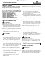
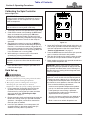
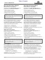
Calibrating the Spin Controller
Refer to Figure 2-1:
1. Thoroughly lubricate the spreader before calibrating.
2. Calibrate the control unit by holding the OFF button
down and momentarily pressing the ON button.
While in the calibration mode, the lights will flash
rapidly. Once calibration is complete, the lights will go
out and gate will close. The unit is now ready for
operation.
3. Set dispensing amount by pressing the MORE or
LESS buttons to achieve the desired gate opening.
Position 1 is the minimum amount and position 6 is
the maximum amount of material flow. The Material
Flow light flashes when unit is not running (OFF) and
is on solid when unit is running (ON).
4. While moving at a constant rate, start material
spreading by pressing the ON button.
5. Press the OFF button to stop the spin motor and
close the control gate.
Field Set-up
WARNING
!
To avoid serious injury or death:
• Wear eye protection to prevent getting chemicals and/or
dirt in the eyes while cleaning the implement.
• Wear proper protective clothing when servicing or
lubricating the spin seeder. Refer to chemical
manufacturers’ labels for specific clothing requirements.
1. Prior to operation, thoroughly lubricate the spin
spreader. Check for proper operation of the
mechanisms by running the spin motor and slide
gate at no-load. See “Calibrating the Spin
Controller” on page 14.
2. Review spreader rate charts beginning on pages 20.
Make initial setting to the spin spreader controller
(positions 1 through 6) and install or remove the
restrictor plate as needed.
3. Install the spin deflector if a narrow pattern (48"
spreading width) is desired or remove the spin
deflector if a wide pattern is preferred.
IMPORTANT: To assure proper operation, the Plot
Ranger controls should be calibrated each time it is
plugged into the 12 volt receptacle or if you loose
power to receptacle.
IMPORTANT: Make sure the spin spreader is empty
and the vehicle is running when calibrating.
NOTE: The MORE or LESS buttons may be
pressed at anytime to achieve the desired material
flow rate.
Spin Spreader Controller
Figure 2-1
4. Lower the Plot Ranger to the ground and make a run
with the spin spreader turned off. Make depth, angle,
and level adjustments to the disc harrow. Refer to
“Section 3: Adjustments” on page 17.
5. Press the OFF button to make sure the spin spreader
gate is closed and fill the bin with product.
6. With the disc blades on the ground, rotate the roller
packer over the spin seeder and onto the ground.
7. Make another run with the spin spreader turned on to
check product dispersion rate.
23910
IMPORTANT: Always make sure you are traveling
before turning the spin spreader on. Always turn the
spin spreader off before end of travel. Running the
spreader while not traveling will discharge too much
material in one spot.
NOTE: A good method for checking product
dispersion is to fill the bin with the required pounds
of material to cover 1,000 sq. ft. in a straight run. A
4 ft. wide pattern would require 250 ft. of straight run.
You should run out of product at the end of the 250
ft. If not, make the following adjustments:
1. Increase travel speed to disperse less product
per sq. ft. or decrease speed to disperse more.
2. If the speed you are traveling is preferred,
change position number on the controller to
disperse more or less product.
3. You may also want to adjust the spin deflector at
the wing nuts to control placement of product.
4. Make a new run to recheck dispersion rate.

Section 2: Operating Procedures
FPS48 Plot Ranger Food Plot Seeder 322-118M12/7/18
15
Table of Contents
Field Operation
WARNING
!
To avoid serious injury or death:
Be careful when working with disc blades as the edges are
sharp. Wear gloves when working around disc blades. Keep
others away.
1. After initial adjustments have been made and you
have hooked up to disc harrow, you are ready to start
discing.
2. Lower disc harrow to the ground and start traveling
forward. Turn the spin spreader on after forward
travel has started and off before travel has stopped.
Your travel speed will be determined by soil
conditions and material dispersion.
3. Allow room to make wide turns or lift the unit out of
the ground to make sharp turns.
4. Do not disc in reverse (traveling backward). The Plot
Ranger is designed for working the soil while
traveling forward only. Damage to the harrow and
roller packer may occur. The recommended
procedure for making sharp corners or harrowing in
tight places is:
a. With the disc harrow in the ground, rotate roller
packer up over disc harrow.
b. Lift disc harrow up.
c. Back up into corner or other tight areas.
d. Lower harrow to ground and proceed with discing
going forward. Stop and lower roller packer as
soon as there is room for it to be lowered.
e. Turn on the seeder if it is being used.
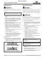
Refer to Figure 2-2:
5. Do not cross a ditch at a 90 degree angle (straight
on)! Damage to the disc harrow and/or vehicle may
occur while crossing at a 90 degree angle. Always
cross a ditch on a diagonal.
Figure 2-2
IMPORTANT: Making too sharp a turn with disc
blades in the ground can damage the blades.
Ditch / Bank
Ditch / Bank
Correct Way to Cross (at a diagonal)
Incorrect Way to Cross (straight on)
Unhook Plot Ranger
DANGER
!
To avoid serious injury or death:
A crushing hazard exists while hooking-up and unhooking
implement. Keep people and animals away while backing-up
to implement or pulling away from implement. Do not operate
hydraulic or electrical controls while a person or animal is
directly behind the power machine or near the implement.
WARNING
!
To avoid serious injury or death:
The disc harrow tongue can have negative tongue weight that
may cause immediate elevation of tongue. Set gauge wheels 1"
above ground before hitching or unhitching from implement.
Store implement with gauge wheels touching the ground.
1. Park on a level solid surface.
2. Lower disc blades to the ground and raise carriage
wheels approximately 1" off the ground. Do not raise
wheels all the way up as this allows the unit to tip
backward.
3. Shut vehicle engine off and engage parking brake.
4. (Optional) Spin Controller Electrical:
a. Unplug lighter plug from 12 volt accessory
receptacle.
b. Unplug hand control from the feedgate.
c. Unplug hand control from the spin motor.
5. (Optional) Linear Actuator Electrical:
a. Unplug the connector at the actuator.
b. Disconnect the black wire alligator clip from the
negative (-) battery post.
c. Disconnect the white wire alligator clip from the
positive (+) battery post.
6. Unhitch Plot Ranger from vehicle.
7. Properly clean the spin spreader per the instructions
on page 25.
8. Remove and store spin spreader, spin controller, and
actuator controller in a dry location.
9. Refer to “Long-Term Storage” on page 26 if the Plot
Ranger is to be stored for the season.
IMPORTANT: Protect the spin controller and
actuator controller from moisture by storing them in
a dry location.
IMPORTANT: Read and understand all instructions
to “Clean the Spin Spreader” on page 25 before
cleaning the spreader.

Section 2: Operating Procedures
FPS48 Plot Ranger Food Plot Seeder 322-118M 12/7/18
16
Table of Contents
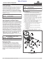
General Operating Instructions
Before putting your Land Pride FPS48 Plot Ranger into
service you must thoroughly review the Operator’s
Manual. Once you have read the Operator’s Manual and
properly set up your Land Pride Plot Ranger system and
attached it to the vehicle you intend to pull it with, you
should be ready to head for the planting site. You should
have already removed any sizable tree limbs, rocks, or
extraneous debris, and should have mowed any tall
grass or weeds. You might have already plowed this area
previously in preparation for planting. Do not attempt to
disc wet or mucky soil and all areas should be well
drained and capable of being walked on without having
the soil stick to your shoes.
The disc can be lowered to the ground with either the
manual ratchet lever or the optional 12 volt linear actuator
with electrical lead. Discing action will commence as
soon as the unit is lowered to the ground and you begin to
pull the unit forward. You will need to make sure you raise
the transport wheels high enough to allow for adequate
disc penetration. Your travel speed forward will be
determined by soil conditions, depth of penetration, and
available horsepower of the pulling vehicle. Never try to
disc in reverse and when you reach the end of a pass,
either raise the unit up on the transport wheels, or make
a wide sweeping turn to realign for the next pass. Turning
too sharply with the disc in the ground will cause extreme
side loading on the discs that could result in damage.
Disc gang adjustments may be required to make discing
and cultivation action more or less aggressive. This is
achieved by raising the disc into transport position,
pulling the locking pins, and making the required
adjustments to the front and rear gangs. The Operator’s
Manual illustrates this process very clearly.
Ground conditions and the seedbed finish you require will
determine how you position the angles of your front and
rear disc gangs. Both of the front and rear disc gangs
have four angle adjustment positions. The more
aggressive you set the angle of the gangs, the more
aggressive the cutting action in the soil profile will be. The
more aggressive the cutting action is, the more
horsepower will be required to pull your unit. Achieving
the desired effect may require a little experimentation in
your given conditions. If the soil is building up on or
sticking to your discs, then the soil is to wet and discing
operations should be discontinued until the ground is
drier and more workable.
Once you are satisfied that you have achieved the right
finish, it’s time to determine what your spin spreader
settings need to be. Land Pride has furnished you with
the seed rate charts that provides suggested settings for
eleven of the most popular types of seeds typically used
in wild game food plots. We have also provided
suggested guidelines for distribution of fertilizers,
gypsum, and lime. Due to the wide number of
possibilities and variables that can and do come into play
when planting, fertilizing, or making soil amendments,
Land Pride makes absolutely no guarantees or
warranties with respect to fertilizer applications, or
actual seed distribution and germination rates.
Initial calibration and set up of the seeder mechanism
should be accomplished with no seed in the hopper.
Using the rate charts you will need to determine which
one of the six position settings you will need to use. You
do need to determine whether or not you will need to use
the restrictor plate in the seed gate opening. You will also
need to determine what your forward travel speed needs
to be. We highly recommend the use of a global
positioning device (GPS) to help maintain your actual
ground speed when planting. To calibrate your seeder
metering system connect your power cable to a 12 volt
receptacle. Turn the power on. Now hold down on the off
button and press the on button momentarily to
synchronize the controller with the seed gate. While in
the calibration mode, the lights will flash rapidly. Once
calibration is complete, the lights will go out and the gate
will close. The unit is now ready for operation.
Press the + positive or - negative control button until the
red light is on directly below the position setting you want.
Now when you hit the off button, the seed gate in the
hopper will close and you can safely put seed in the
hopper.
When you hit the on button, the seed gate will now
automatically open to the position setting you have
chosen and spinner will begin rotating and distributing
seed. At that time you should also be traveling at the
ground speed you have preselected for the proper
distribution rate, you should have the disc on the ground
in working position, and the fluted roller/packer should be
flipped down in working position to help achieve
maximum seed to soil contact. When you hit the off button
again the seed gate will automatically close and the
spinner will stop. If you need to adjust the seed rate up or
down this can be done at any time by simply pushing the
negative or positive control buttons to change the
indicated position settings. This seeder has some
minimal overlap which will generally result in a more
uniform stand between adjacent planting passes.
Once you are finished using your Plot Ranger, park it on
a dry and level surface, clean it, and make it ready for the
next use. Never leave seed, fertilizer, or any other
materials in the hopper or serious damage to the seed
metering system could result. Put the lid on the seed
hopper and store the electronic lead controls in a clean
and dry manner. Attaching and detaching the ball or pin
type pull hitch can be easily accomplished by lowering
the disc to the ground and slightly raising the transport
wheels to achieve neutral or slightly negative tongue
weight. Be careful not to achieve to much negative
tongue weight or the hitch could jump quickly upward
when released from the hitch With a little practice you
will be able to achieve excellent results from your Land
Pride Plot Ranger. See “Features and Benefits” section
or “Product Specifications” for additional information
and performance enhancing options.
Page is loading ...
Page is loading ...
Page is loading ...
Page is loading ...
Page is loading ...
Page is loading ...
Page is loading ...
Page is loading ...
Page is loading ...
Page is loading ...
Page is loading ...
Page is loading ...
Page is loading ...
Page is loading ...
Page is loading ...
Page is loading ...
Page is loading ...
Page is loading ...
-
 1
1
-
 2
2
-
 3
3
-
 4
4
-
 5
5
-
 6
6
-
 7
7
-
 8
8
-
 9
9
-
 10
10
-
 11
11
-
 12
12
-
 13
13
-
 14
14
-
 15
15
-
 16
16
-
 17
17
-
 18
18
-
 19
19
-
 20
20
-
 21
21
-
 22
22
-
 23
23
-
 24
24
-
 25
25
-
 26
26
-
 27
27
-
 28
28
-
 29
29
-
 30
30
-
 31
31
-
 32
32
-
 33
33
-
 34
34
-
 35
35
-
 36
36
-
 37
37
-
 38
38


Ask a question and I''ll find the answer in the document
Finding information in a document is now easier with AI
Related papers
-
 Land Pride Electric Lift Actuator 322-119A User manual
-
 Land Pride PTS User manual
-
 Land Pride Spreader 322-118P User manual
-
 Land Pride DH15 User manual
-
 Land Pride OS15 User manual
-
 Land Pride 322-215M User manual
-
 Land Pride PS1572 User manual
-
Land Pride DH7100 Series User manual
-
 Land Pride NTS26 User manual
-
 Land Pride DH10 User manual


Other documents
-
BCS 32" Power Harrow Owner's manual
-
Swisher 12593 Owner's manual
-
 Red Rock 8578775 Owner's manual
-
 Mail Boss 7135 Installation guide
-
Drive Medical Tracheotomy Mask 50/case Owner's manual
-
Drive Medical Tracheotomy Mask 50/case Owner's manual
-
Simplicity 206 User manual
-
 AGT INDUSTRIAL AGT-NTSD-7 Owner's manual
-
CHICAGO 5002 Owner's Instructions Manual
-
Life Fitness 9000 Treadmills User manual


