Page is loading ...

FXTH87 Family Evaluation Design
Reference Manual
Devices Supported:
FXTH870511
FXTH870911
FXTH871511
Document Number: FXTH87EDRM
Rev. 1.0, 09/2015

Document Number: FXTH87EDRM
Rev. 1.0
09/2015
Information in this document is provided solely to enable system and software
implementers to use Freescale products. There are no express or implied copyright
licenses granted hereunder to design or fabricate any integrated circuits based on the
information in this document.
Freescale reserves the right to make changes without further notice to any products
herein. Freescale makes no warranty, representation, or guarantee regarding the
suitability of its products for any particular purpose, nor does Freescale assume any
liability arising out of the application or use of any product or circuit, and specifically
disclaims any and all liability, including without limitation consequential or incidental
damages. “Typical” parameters that may be provided in Freescale data sheets and/or
specifications can and do vary in different applications, and actual performance may
vary over time. All operating parameters, including “typicals,” must be validated for each
customer application by customer’s technical experts. Freescale does not convey any
license under its patent rights nor the rights of others. Freescale sells products pursuant
to standard terms and conditions of sale, which can be found at the following address:
freescale.com/salestermsandconditions.
How to Reach Us:
Home Page:
freescale.com
Web Support:
freescale.com/support
Freescale and the Freescale logo are trademarks of Freescale Semiconductor, Inc.,
Reg. U.S. Pat. & Tm. Off. All other product or service names are the property of their
respective owners.
© 2014-2015 Freescale Semiconductor, Inc.

FXTH87 Family Evaluation Design Reference Manual, Rev. 1.0
Freescale Semiconductor, Inc. 1
Contents
Chapter 1 Introduction and Setup
1.1 Introduction . . . . . . . . . . . . . . . . . . . . . . . . . . . . . . . . . . . . . . . . . . . . . . . . . . . . . . . . . . . .2
1.2 FXTH87 Family Tire Pressure Monitoring Sensor module features . . . . . . . . . . . . . . . . .3
1.3 Board programming guide . . . . . . . . . . . . . . . . . . . . . . . . . . . . . . . . . . . . . . . . . . . . . . . . .4
1.3.1 Downloading demo software to FXTH87 modules, LF 125-kHz emitter and TPMS
receiver . . . . . . . . . . . . . . . . . . . . . . . . . . . . . . . . . . . . . . . . . . . . . . . . . . . . . . . .4
Chapter 2 Schematics and Bill of Materials
2.1 FXTH87 module evaluation boards (EVB) . . . . . . . . . . . . . . . . . . . . . . . . . . . . . . . . . . . . .6
Chapter 3 FXTH87 Main Features and Specific Information
3.1 LF receiver . . . . . . . . . . . . . . . . . . . . . . . . . . . . . . . . . . . . . . . . . . . . . . . . . . . . . . . . . . . .10
3.1.1 LF sampling frequency . . . . . . . . . . . . . . . . . . . . . . . . . . . . . . . . . . . . . . . . . . . .10
3.1.2 LF datagram recommended shape using the data mode . . . . . . . . . . . . . . . . . .11
3.1.3 Example of init and decoding function with data mode . . . . . . . . . . . . . . . . . . . .13
Example 3-1.Init . . . . . . . . . . . . . . . . . . . . . . . . . . . . . . . . . . . . . . . . . . . . . . . . .13
Example 3-2.Decoding . . . . . . . . . . . . . . . . . . . . . . . . . . . . . . . . . . . . . . . . . . . .13
3.1.4 LF datagram recommended shape using the MCU-direct mode . . . . . . . . . . . .15
3.1.5 Decoding function with MCU-direct mode . . . . . . . . . . . . . . . . . . . . . . . . . . . . .16
Example 3-3.Init . . . . . . . . . . . . . . . . . . . . . . . . . . . . . . . . . . . . . . . . . . . . . . . . .16
Example 3-4.Decoding . . . . . . . . . . . . . . . . . . . . . . . . . . . . . . . . . . . . . . . . . . . .17
3.2 RF transmitter . . . . . . . . . . . . . . . . . . . . . . . . . . . . . . . . . . . . . . . . . . . . . . . . . . . . . . . . .19
3.2.1 RF block general information . . . . . . . . . . . . . . . . . . . . . . . . . . . . . . . . . . . . . . .19
3.2.2 RF output impedance . . . . . . . . . . . . . . . . . . . . . . . . . . . . . . . . . . . . . . . . . . . . .19
3.2.3 RF MCU-direct code example . . . . . . . . . . . . . . . . . . . . . . . . . . . . . . . . . . . . . .20
Example 3-5.Software example . . . . . . . . . . . . . . . . . . . . . . . . . . . . . . . . . . . . .21
3.3 X- and Z-axis accelerometers . . . . . . . . . . . . . . . . . . . . . . . . . . . . . . . . . . . . . . . . . . . . .24
3.3.1 Acceleration X and Z acquisition . . . . . . . . . . . . . . . . . . . . . . . . . . . . . . . . . . . .24
Chapter 4 Firmware Function Example
Example 4-1. . . . . . . . . . . . . . . . . . . . . . . . . . . . . . . . . . . . . . . . . . . . . . . . . . . . .26
Revision History . . . . . . . . . . . . . . . . . . . . . . . . . . . . . . . . . . . . . . . . . . . . . . . . . . . . . . . . . . . .30
Related Documentation
The FXTH87 device features and operations are described in a variety of reference manuals, user guides, and application notes.
To find the most-current versions of these documents:
1. Go to the Freescale homepage at:
http://www.freescale.com/
2. In the Keyword search box at the top of the page, enter the device number FXTH87.
3. In the Refine Your Result pane on the left, click on the Documentation link.

FXTH87 Family Evaluation Design Reference Manual, Rev. 1.0
Freescale Semiconductor, Inc. 2
Chapter 1 Introduction and Setup
1.1 Introduction
The purpose of this document is to provide the end user with all the technical information required to
become quickly familiar with the FXTH87 Family Evaluation Tire Pressure Monitoring Sensor (TPMS)
devices.
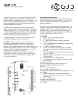
The tool set of the TPMS kit consists of one FXTH870511 module for 450-kPa evaluations, one
FXTH870911 module for 900-kPa evaluations, one FXTH871511 module for 1500-kPa evaluations and
the associated software.
Figure 1-1. Tool set of TPMS

Introduction and Setup
FXTH87 Family Evaluation Design Reference Manual, Rev. 1.0
Freescale Semiconductor, Inc. 3
1.2 FXTH87 Family Tire Pressure Monitoring Sensor module features
•8-bit MCU
• S08 Core with SIM, interrupt and debug/monitor
• 512 RAM
• 8K FLASH (in addition to 8K providing factory firmware and trim data)
• 64-bytes, low power, parameter registers
• Four GPIO pins with optional pullups/pulldowns and wake-up interrupt
• Real-time interrupt driven by low-frequency oscillator (LFO) with interrupt intervals of 8, 16, 32,
64, 128, 256, 512 or 1024 msec
• Low-power, wake-up timer and periodic reset driven by LFO
• Watchdog timeout with selectable times and clock sources
• Two-channel general purpose timer/PWM module (TPM1)
• Internal oscillators
• MCU bus clock nominal of 0.5, 1, 2 and 4 MHz (1, 2, 4 and 8 MHz HFO)
• Low-frequency, low-power time clock (LFO) with 1 msec nominal period
• Low-frequency receiver (LFR) decoder and sensor clock (MFO) of 8 µsec nominal period
• Low-voltage detection
• Normal temperature restart in hardware (over temperature detected by software)
• Differential input LF detector/decoder
• Temperature sensor with signal interface to ADC10
• Pressure sensor with signal interface to ADC10
• X- and Z-axis accelerometers with signal interface to ADC10
• Voltage reference measured by ADC10
• Internal 315/434 MHz RF transmitter
— External-crystal oscillator
— ASK and FSK modulation capability
— Programmable data-rate generator
— Manchester or bi-phase data encoding
— 128 bit RF data buffer with RTS/CTS handshake
— Direct access to RF transmitter from MCU for unique formats
• 8-bit MCU programming capability through the four pins connector and the BDM multilink type
• Dedicated matching network circuit for optimal performances with the antenna
• Typical wireless range is 50 meters in air with a 5 dBm output power
• 3 V battery solder pads

Introduction and Setup
FXTH87 Family Evaluation Design Reference Manual, Rev. 1.0
4 Freescale Semiconductor, Inc.
Figure 1-2. FXTH87 Module
1.3 Board programming guide
1.3.1 Downloading demo software to FXTH87 modules, LF 125-kHz
emitter and TPMS receiver
The software project can be downloaded on the FXTH87 modules. The connection to the BDM Multilink
is done through an interface socket for the FXTH87 modules and a P&E BDM Multilink interface (see
Figure 1-3).

Introduction and Setup
FXTH87 Family Evaluation Design Reference Manual, Rev. 1.0
Freescale Semiconductor, Inc. 5
Figure 1-3. FXTH87 Family TPMS module

FXTH87 Family Evaluation Design Reference Manual, Rev. 1.0
Freescale Semiconductor, Inc. 6
Chapter 2 Schematics and Bill of Materials
2.1 FXTH87 module evaluation boards (EVB)
Figure 2-1. Typical reference demonstrator for FXTH87 315 MHz

Schematics and Bill of Materials
FXTH87 Family Evaluation Design Reference Manual, Rev. 1.0
Freescale Semiconductor, Inc. 7
Figure 2-2. Typical reference demonstrator for FXTH87 434 MHz
L2 and R2 matching network values are applicable when using the hook antenna available on the module.
Any change in the antenna characteristics will need a re-adjustment of the matching network.

Schematics and Bill of Materials
FXTH87 Family Evaluation Design Reference Manual, Rev. 1.0
8 Freescale Semiconductor, Inc.
Table 2-1. FXTH87 reference demonstrator bill of material (315 MHz and 434 MHz)
Ref. # Value Footprint
Freescale recommended
preferred products
Supplier
Y1 26 MHz QUARTZ_3225
NX3225SA-26.0000 MHz
EXS00A-CS01003
NDK
C1 OPEN SM/C_0402 — —
C2 220 pF@315 MHz SM/C_0402 — —
C3
OPEN@315 MHz
and
1 pF@434 MHz
SM/C_0402
——
C4 OPEN SM/C_0402 — —
C5 0.1 µF SM/C_0402 — —
C6 100 pF SM/C_0402 — —
C7 OPEN SM/C_0402 — —
C8 0.47 µF SM/C_0402 — —
C9 10 pF SM/C_0402 — —
C10 10 pF SM/C_0402 — —
C11 220 pF SM/C_0402 — —
ANTENNA N/A RF ANTENNA N/A Freescale design
J1 JUMPER POWER JUMPER — —
J20 CON4 PROG. CONN. — —
L1
110 nH@434 MHz 0402
100 nH@434 MHz 0603
SM/C_0402
or
SM/C_0603
MLG1005SR11HTD25
MLG1608BR10JTD25
TDK
TDK
L2 OPEN SM/C_0402 — —
L3
0402 and 0603
47 nH @315 MHz
39 nH @434 MHz
SM/C_0402
or
SM/C_0603
MLG1005S47NHTD25@315 MHz 0402
MLG1608B47NJTD25@315 MHz 0603
MLG1005S39NHTD25@434 MHz 0402
MLG1608B39NJTD25@434 MHz 0603
TDK
TDK
TDK
TDK
L4 10 nH SM/C_0402 MLK1005S10NJTD25 TDK
L5 7.2 mH LF COIL B82450A7204A000 EPCOS
R1 0 Ω @434 MHz SM/C_0402 — —
R2 0 Ω SM/C_0402 — —
R3 0 Ω SM/C_0402 — —
R4 OPEN SM/C_0402 — —
R5 0 Ω SM/C_0402 — —
R6 0 Ω SM/C_0402 — —
R7 OPEN SM/C_0402 — —
R8 10 kΩ SM/C_0402 — —
R9 OPEN SM/C_0402 — —
R10 0 Ω @315 MHz SM/C_0402 — —
R20 OPEN SM/C_0402 — —

Schematics and Bill of Materials
FXTH87 Family Evaluation Design Reference Manual, Rev. 1.0
Freescale Semiconductor, Inc. 9
R21 OPEN SM/C_0402 — —
R22 OPEN SM/C_0402 — —
R23 OPEN SM/C_0402 — —
R24 4.7 kΩ SM/C_0402 — —
R25 OPEN SM/C_0402 — —
R26 4.7 kΩ SM/C_0402 — —
U1 FXTH870511 – 450 kPa QFN 7 x 7 FXTH870511 – 450 kPa Freescale
U1 FXTH870911 – 900 kPa QFN 7 x 7 FXTH870911 – 900 kPa Freescale
U1 FXTH871511 – 1500 kPa QFN 7 x 7 FXTH871511 – 1500 kPa Freescale
Table 2-1. FXTH87 reference demonstrator bill of material (315 MHz and 434 MHz) (continued)
Ref. # Value Footprint
Freescale recommended
preferred products
Supplier

FXTH87 Family Evaluation Design Reference Manual, Rev. 1.0
Freescale Semiconductor, Inc. 10
Chapter 3 FXTH87 Main Features and Specific Information
3.1 LF receiver
The LF block allows wake-up of the FXTH87 device from STOP1 (low-power) mode when a carrier or a
Manchester datagram is detected. If the LF datagram is coded in Manchester, it will be decoded by the
embedded LF state machine assuming the LF module has been configured appropriately. In addition, this
LF receiver (LFR) system can autonomously listen for valid LF signals, check for protocol and ID
information so the main MCU can remain in a very low-power standby mode until valid message data has
been received. The LFR does not wake the MCU unless a valid message is being received and a data byte
is ready to be read.
3.1.1 LF sampling frequency
Power consumption optimization is obtained with the LFR cycling between an OFF state, where
everything is disabled, and an ON state, where it listens for a carrier signal.
When the LFR is listening for a carrier signal, only the internal 1-kHz clock source (LFO), a portion of the
input amplifier and a periodic auto-zero circuitry are running. If a carrier signal with the correct frequency
and higher-than-threshold amplitude is detected, and the internal oscillator to the LFR (LFRO) is enabled,
the module begins to decode the incoming message. For adequate LF telegram sampling, a point to take
into consideration is the accuracy of the sampling time directly linked to the accuracy of the 1-kHz LFO
clock, which varies from 769 to 1428 Hz, according to the product specification.
It is therefore recommended to use the appropriate sampling timing with respect to the incoming LF signal
duration. Sampling time is selectable through the LFCR register content.
As an example, if there is a request for sampling an incoming 16-msec carrier length every 16 msec
(LFON = 1 msec), a hit rate of 100 percent will not be achieved.
• With LFO = 1428 Hz, the signal will be sampled every 16/1428 = 11.2 msec giving a high hit rate.
• With LFO = 769 Hz, the signal will be sampled every 16/769 = 20.8 msec giving a low hit rate.
For a 16-msec carrier length LF signal, the recommendation is to sample the signal every 8 msec with the
LF sampling interval set continuously ON. This will give a sampling interval between 5.6 and 10.4 msec
when taking into account the frequency of the LFO, improving the quality of the hit rate.

FXTH87 Main Features and Specific Information
FXTH87 Family Evaluation Design Reference Manual, Rev. 1.0
Freescale Semiconductor, Inc. 11
3.1.2 LF datagram recommended shape using the data mode
In data mode when a carrier is detected, the averaging filter is powered on and the LFR continues to the
next state to look for the rest of a message telegram. The LFR module will search for a valid SYNC word
(with length programmed through the SYNC bits in the LFCTL3 register depending on preamble type). If
the external LF field is not a valid TPMS frame, a timeout will turn off the LFR module decoder, and will
cycle back to the on-off detection scheme as described in Section 3.1.1, “LF sampling frequency”.
Data-clock recovery and synchronization takes place before or during the SYNC portion of an incoming
message. The preamble can be nothing, a carrier only or modulated Manchester data. The type of required
SYNC pattern determines the allowed preamble type depending on the SYNC[1:0] control bits.
The design data rate is 3.906 kbps which gives a bit time equivalent to about 32 cycles of the LF-carrier
frequency. In a Manchester encoded bit time, the carrier should be present for either the first half or the
second half of the bit time depending on whether the bit is a logic zero or a logic one.
The example below provides a recommended Freescale LF datagram format.
NOTE
Different automotive manufacturers have their own defined protocols, the
example above is only provided as reference.
It is composed of:
• A 4 msec of CW preamble
• Two data transitions to allow a clean demodulation establishment
•Nine t
DATA
synchronizations
• 16 bits of wake-up bytes (x5E and x31)
• Four bytes of data (x13, xC6, x6C, x3A)
• One end of message frame (illegal Manchester bit at a databyte boundary)

FXTH87 Main Features and Specific Information
FXTH87 Family Evaluation Design Reference Manual, Rev. 1.0
12 Freescale Semiconductor, Inc.
Figure 3-1. Example of Manchester LF telegram
Figure 3-2. LF telegram and decoding check

FXTH87 Main Features and Specific Information
FXTH87 Family Evaluation Design Reference Manual, Rev. 1.0
Freescale Semiconductor, Inc. 13
3.1.3 Example of init and decoding function with data mode
Example 3-1. Init
/******************************************************************************
function :Init_LF(void)
parameters :void
returns :void
type :low level c
description: LF Setup
*******************************************************************************/
void Init_LF(void)
{
LFS=0x03; //Low consumption during sniff mode
//Clears the LFDRF, LFERF, LFCDF, LFIDF, LFOVF and LFEOMF flag bits.
LFCTL1=0x19; // LPAGE=1
LFCTRLD=0x03; //CARVAL validates on 1 times 4 edges inside a 32 usec window
LFCTRLC=0xC9; //RESET Value with High Level Attenuator system enabled
LFCTRLB=0xC4; //RESET Value with POL=0
LFCTRLA=0x00; //RESET Value
LFCTL1=0x8A; // LPAGE=0 and LFON - 16 bit ID - Sensitivity = Low
LFCTRLA=0x00; //RESET Value
LFIDL=0x31; //Wake-up codes defined by user MSB
LFIDH=0x5E; //Wake-up codes defined by user LSB
}
Example 3-2. Decoding
/****************************************************************************
Function: Decode_LF_Datagram - Manchester
NOTES: LF data decoding through Interrupt
*****************************************************************************/
void Decode_LF_Datagram()
{
unsigned char ii;
LFDatagram[0]= LFDATA;
for (ii=1;ii<4;ii++)
{
while(LFS_LFDRF==0); // Loop until LFDRF Flag is set
{
LFDatagram[ii]=LFDATA;
}
}
LFDATA=0x00;
/**************LF0 detection********************/
if (LFDatagram[0]==0x13 && LFDatagram[1]==0xC6 && LFDatagram[2]==0x6C &&
LFDatagram[3]==0x3A)// && LFDatagram[4]==0x4F && LFDatagram[5]==0x62) //LF0
{
TogglePTA0();
}

FXTH87 Main Features and Specific Information
FXTH87 Family Evaluation Design Reference Manual, Rev. 1.0
14 Freescale Semiconductor, Inc.
else
{
/* Nothing */
}
LF_OFF();
LFS_LFIACK=1;
EnableInterrupts;
}
Figure 3-3. LF telegram (Synchro/5 Tbit/Preamble detail)

FXTH87 Main Features and Specific Information
FXTH87 Family Evaluation Design Reference Manual, Rev. 1.0
Freescale Semiconductor, Inc. 15
3.1.4 LF datagram recommended shape using the MCU-direct mode
When the LF is operating in MCU-direct mode, the MCU shall poll the LFDO bit to extract from the
analog detector the bit stream. To assure an LFDO bit ready state, a transition in the XX register must be
added between the preamble and the first data byte. This transition is used as the synchro. The CH2 is used
to keep track of the preamble and the synchro detections and the test of a decoding. For more details on
the MCU-direct mode, please refer to the FXTH87 family product specification.
The LF telegram to decode is composed by:
• Eight msec Preamble
• 600-μsec Synchro
• Five bytes of data’s (xD5, x05, xAA, xCA, xEE)
• 0 is coded with a 1-msec width, 1 is coded with a 2-msec width
Figure 3-4. LF telegram used for MCU-direct mode example

FXTH87 Main Features and Specific Information
FXTH87 Family Evaluation Design Reference Manual, Rev. 1.0
16 Freescale Semiconductor, Inc.
3.1.5 Decoding function with MCU-direct mode
Example 3-3. Init
/*******************************************************************************
function : Init_TPM1CH0()
parameters : void
returns : void
type : low level c
description:
This function initializes TIMER1 CHANNEL 0
*******************************************************************************/
void Init_TPM1CH0(void)
{
TPM1SC=0x08 | 0x02;// 4F CLOCK TIMER = FBUS=8MHz/128 - set Timer ON
TPM1C0SC=0x00; //Configure in TBM , Interrupt Enable address
TPM1MODH=0xFF; // FF Fixed the OC every 1.13sec
TPM1MODL=0xFF; // FF Fixed the OC every 1.13sec
}
/******************************************************************************
function :Init_LF(void)
parameters :void
returns :void
type :low level c
description: LF Setup
*******************************************************************************/
void Init_LF(void)
{
LFS_LFIACK=1;
LFCTL1=0x10; // LPAGE=1
delay(20);
LFCTL1=0x00; // LPAGE=0
delay(20);
LFCTL3_TOGMOD=0;
//Digital decoder is disabled.
delay(20);
LFCTL1_LFEN=1;
}

FXTH87 Main Features and Specific Information
FXTH87 Family Evaluation Design Reference Manual, Rev. 1.0
Freescale Semiconductor, Inc. 17
Example 3-4. Decoding
/****************************************************************************
Function: Decode_LF_Datagram -Manchester 01/04/2008 Optimized
NOTES: LF data decoding through Interrupt
*****************************************************************************/
void Decode_LF_Datagram()
{
unsigned int e,f;
byte i,j,l;
DisableInterrupts; /* Disable interrupts */
/*** Init IO ***/
PTAD=0x00;
PTADD=0x03; /*PTA0,1 configured as an Output */
e=0;
Init_TPM1CH0();
TPM1CNT=0; //clear timer contents to avoid overflow
/*** Preambule detect and NAND condition ***/
PTAD=0x01;
PTAD=0x00;
//Time count to be in the area of NO CW before the 1 msec Synchro pulse
while (TPM1CNT<8000);
// Stays in the NO CW area before the Synchro and wait for the LFDO set to 1
while (LFCTL3_LFDO==0);
PTAD=0x01;
PTAD=0x00;
/** Synchro detection **/
TPM1CNT=0; //clear timer contents to avoid timing cumulation
while (!((LFCTL3_LFDO!=1) && (TPM1CNT>500))); //wait LFDO stays to One
e= TPM1CNT + e; //Store Timer Value
PTAD=0x01;
PTAD=0x00;
TPM1CNT=0; //clear timer contents to avoid timing cumulation
while (!((LFCTL3_LFDO!=0) && (TPM1CNT>500))); //wait LFDO stays to
Zero);
e= TPM1CNT + e; //Store Timer Value
PTAD=0x01;
PTAD=0x00;
TPM1CNT=0; //clear timer contents to avoid overflow
/******** DECODING LOOP *******/
j=0;
for (l=0;l<=4;l++)
{
do
{
TPM1CNT=0; //clear timer contents to avoid overflow
e=TPM1CNT;
PTAD=0x02; //PTA1 ON
while (!((LFCTL3_LFDO!=1) && (TPM1CNT>850))); //wait LFDO stays to One
f=TPM1CNT;
e= TPM1CNT + e; //Store Timer Value

FXTH87 Main Features and Specific Information
FXTH87 Family Evaluation Design Reference Manual, Rev. 1.0
18 Freescale Semiconductor, Inc.
PTAD=0x00;
TPM1CNT=0;
while (!((LFCTL3_LFDO!=0) && (TPM1CNT>850))); //wait
LFDO stays to Zero);
e= TPM1CNT + e; //Store Timer Value
if ( f>1800 && f<2400)
{
LFDatagram[l] |= (1 << (7-j)); // CREATE A ONE
}
if (f>650 && f<1250)
{
LFDatagram[l] &= ~(1 << (7-j)); // CREATE A ZERO
}
j++;
} while(j<8);
j=0;
}
if (LFDatagram[0]==213 && LFDatagram[1]==85 && LFDatagram[2]==170 &&
LFDatagram[3]==202 && LFDatagram[4]==238)
{
TogglePTA0();
}
LF_OFF();
LFCTL4_LFCDIE=1;
LFS_LFIACK=1; // Clear LF Flags
asm{cli;}
}
/