Grizzly Industrial G9984 Owner's manual

Type
Owner's manual

This manual is also suitable for

COPYRIGHT © APRIL, 2002 BY GRIZZLY INDUSTRIAL, INC. REVISED JANUARY, 2019 (RS)
WARNING: NO PORTION OF THIS MANUAL MAY BE REPRODUCED IN ANY SHAPE
OR FORM WITHOUT THE WRITTEN APPROVAL OF GRIZZLY INDUSTRIAL, INC.
PRINTED IN TAIWAN
V2.01.19
MODEL G9984/G9985
OSCILLATING EDGE SANDER
OWNER'S MANUAL
(For models manufactured since 07/18)
This manual provides critical safety instructions on the proper setup,
operation, maintenance, and service of this machine/tool. Save this
document, refer to it often, and use it to instruct other operators.
Failure to read, understand and follow the instructions in this manual
may result in fire or serious personal injury—including amputation,
electrocution, or death.
The owner of this machine/tool is solely responsible for its safe use.
This responsibility includes but is not limited to proper installation in
a safe environment, personnel training and usage authorization,
proper inspection and maintenance, manual availability and compre-
hension, application of safety devices, cutting/sanding/grinding tool
integrity, and the usage of personal protective equipment.
The manufacturer will not be held liable for injury or property damage
from negligence, improper training, machine modifications or misuse.
Some dust created by power sanding, sawing, grinding, drilling, and
other construction activities contains chemicals known to the State
of California to cause cancer, birth defects or other reproductive
harm. Some examples of these chemicals are:
Lead from lead-based paints.
Crystalline silica from bricks, cement and other masonry products.
Arsenic and chromium from chemically-treated lumber.
Your risk from these exposures varies, depending on how often you
do this type of work. To reduce your exposure to these chemicals:
Work in a well ventilated area, and work with approved safety equip-
ment, such as those dust masks that are specially designed to filter
out microscopic particles.
Table Of Contents
PAGE
1. SAFETY
SAFETY RULES FOR POWER TOOLS ..............................................................2-3
ADDITIONAL SAFETY INSTRUCTIONS FOR EDGE SANDERS .......................... 4
2. CIRCUIT REQUIREMENTS
220V SINGLE-PHASE OPERATION ....................................................................... 5
220V THREE-PHASE OPERATION ........................................................................ 5
GROUNDING ........................................................................................................... 6
EXTENSION CORDS .............................................................................................. 6
3. INTRODUCTION
COMMENTARY ....................................................................................................... 7
UNPACKING ......................................................................................................... 8-9
PIECE INVENTORY ................................................................................................ 9
HARDWARE RECOGNITION CHART .................................................................. 10
CLEAN UP ............................................................................................................. 11
SITE CONSIDERATION ........................................................................................ 11
4. ASSEMBLY
BEGINNING ASSEMBLY ...................................................................................... 12
RUBBER FEET ...................................................................................................... 12
BASE SUPPORTS ................................................................................................. 13
5. ADJUSTMENTS
POWER SWITCH .................................................................................................. 14
DUST COLLECTION ............................................................................................. 14
SANDING BELT ROTATION ................................................................................. 15
SANDING BELT REPLACEMENT ......................................................................... 15
SANDING BELT TRACKING ................................................................................. 16
MAIN TABLE HEIGHT ........................................................................................... 16
MAIN TABLE ANGLE ............................................................................................ 17
MITER GAUGE .................................................................................................17-18
SIDE TABLE HEIGHT............................................................................................ 18
SIDE TABLE ANGLE ............................................................................................. 18
6. OPERATIONS
TEST RUN ............................................................................................................. 19
SANDING BELTS .................................................................................................. 19
7. MAINTENANCE
GENERAL .............................................................................................................. 20
TABLES ................................................................................................................. 20
LUBRICATION ....................................................................................................... 20
8. CLOSURE .................................................................................................................... 21
WIRING DIAGRAM.......................................................................................................22-24
DATA SHEET ...............................................................................................................25-26
PARTS DIAGRAM AND LIST ......................................................................................27-36
WARRANTY AND RETURNS ...................................................................................... 39-41
-2- G9984/G9985 (Mfd. Since 07/18)
SECTION 1: SAFETY
For Your Own Safety Read Instruction
Manual Before Operating This Equipment
Indicates an imminently hazardous situation which, if not avoided,
WILL result in death or serious injury.
Indicates a potentially hazardous situation which, if not avoided,
COULD result in death or serious injury.
Indicates a potentially hazardous situation which, if not avoided,
MAY result in minor or moderate injury. It may also be used to alert
against unsafe practices.
This symbol is used to alert the user to useful information about
proper operation of the equipment.
The purpose of safety symbols is to attract your attention to possible hazardous conditions. This
manual uses a series of symbols and signal words which are intended to convey the level of
importance of the safety messages. The progression of symbols is described below. Remember
that safety messages by themselves do not eliminate danger and are not a substitute for proper
accident prevention measures.
NOTICE
Safety Instructions For Power Tools
5. KEEP CHILDREN AND VISITORS AWAY.
All children and visitors should be kept a
safe distance from work area.
6. MAKE WORKSHOP CHILD PROOF with
padlocks, master switches, or by removing
starter keys.
7. DO NOT FORCE TOOL. It will do the job
better and safer at the rate for which it was
designed.
8. USE RIGHT TOOL. Do not force tool or
attachment to do a job for which it was not
designed.
1. KEEP GUARDS IN PLACE and in working
order.
2. REMOVE ADJUSTING KEYS AND
WRENCHES. Form habit of checking to
see that keys and adjusting wrenches are
removed from tool before turning on.
3. KEEP WORK AREA CLEAN. Cluttered
areas and benches invite accidents.
4. DO NOT USE IN DANGEROUS
ENVIRONMENT. Do not use power tools in
damp or wet locations, or where any flam-
mable or noxious fumes may exist. Keep
work area well lighted.
G9984/G9985 (Mfd. Since 07/18) -3-
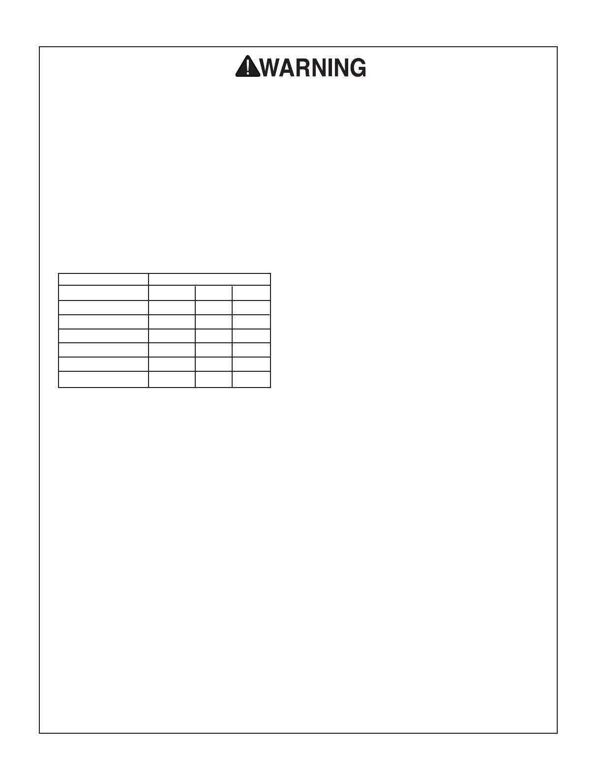
9. USE PROPER EXTENSION CORD. Make
sure your extension cord is in good con-
dition. Conductor size should be in accor-
dance with the chart below. The amperage
rating should be listed on the motor or tool
nameplate. An undersized cord will cause
a drop in line voltage resulting in loss of
power and overheating. Your extension
cord must also contain a ground wire and
plug pin. Always repair or replace exten-
sion cords if they become damaged.
Minimum Gauge for Extension Cords
10. WEAR PROPER APPAREL. Do not wear
loose clothing, gloves, neckties, rings,
bracelets, or other jewelry which may get
caught in moving parts. Non-slip footwear
is recommended. Wear protective hair cov-
ering to contain long hair.
11. ALWAYS USE SAFETY GLASSES. Also
use face or dust mask if cutting operation
is dusty. Everyday eyeglasses only have
impact resistant lenses, they are NOT safety
glasses.
12. SECURE WORK. Use clamps or a vise to
hold work when practical. It’s safer than using
your hand and frees both hands to operate
tool.
13. DO NOT OVER-REACH. Keep proper
footing and balance at all times.
14. MAINTAIN TOOLS WITH CARE. Keep
tools sharp and clean for best and safest
performance. Follow instructions for lubri-
cating and changing accessories.
15. USE RECOMMENDED ACCESSORIES.
Consult owner’s manual for recommended
accessories. The use of improper accesso-
ries may cause risk of injury.
Safety Instructions For Power Tools
16. REDUCE THE RISK OF UNINTENTIONAL
STARTING. On machines with magnetic
contact starting switches there is a risk of
starting if the machine is bumped or jarred.
Always disconnect from power source
before adjusting or servicing. Make sure
switch is in OFF position before reconnecting.
17. MANY WOODWORKING TOOLS CAN
“KICKBACK” THE WORKPIECE toward
the operator if not handled properly. Know
what conditions can create “kickback” and
know how to avoid them. Read the manual
accompanying the machine thoroughly.
18. CHECK DAMAGED PARTS. Before fur-
ther use of the tool, a guard or other
part that is damaged should be carefully
checked to determine that it will operate
properly and perform its intended func-
tion. Check for alignment of moving parts,
binding of moving parts, breakage of parts,
mounting, and any other conditions that
may affect its operation. A guard or other
part that is damaged should be properly
repaired or replaced.
19. NEVER LEAVE TOOL RUNNING
UNATTENDED. TURN POWER OFF. Do
not leave tool until it comes to a complete
stop.
20. NEVER OPERATE A MACHINE WHEN
TIRED, OR UNDER THE INFLUENCE OF
DRUGS OR ALCOHOL. Full mental alert-
ness is required at all times when running
a machine.
21. NEVER ALLOW UNSUPERVISED OR
UNTRAINED PERSONNEL TO OPERATE
THE MACHINE. Make sure any instruc-
tions you give in regards to machine opera-
tion are approved, correct, safe, and clearly
understood.
22. IF AT ANY TIME YOU ARE EXPERIENC-
ING DIFFICULTIES performing the intend-
ed operation, stop using the machine! Then
contact our service department or ask a
qualified expert how the operation should
be performed.
LENGTH
AMP RATING 25ft 50ft 100ft
0-6 18 16 16
7-10 18 16 14
11-12 16 16 14
13-16 14 12 12
17-20 12 12 10
21-30 10 10 No
-4- G9984/G9985 (Mfd. Since 07/18)
No list of safety guidelines can be com-
plete. Every shop environment is different.
Always consider safety first, as it applies
to your individual working conditions. Use
this and other machinery with caution and
respect. Failure to follow guidelines could
result in serious personal injury, damage to
equipment or poor work results.
Additional Safety Instructions For The
Oscillating Belt Edge Sander
DO NOT allow anyone to stand near the
sander while sanding wood stock.
DO NOT jam the workpiece against the
sanding belt. Firmly grasp the workpiece in
both hands and ease it against the sand-
ing belt using light pressure.
DO NOT wear loose clothing while operat-
ing this machine. Roll up or button sleeves
at the cuff.
DO NOT place hands near, or in contact
with, sanding belt during operation.
ANY PROBLEM, with the exception of
belt tracking, that is concerned at all with
any moving parts or accessories must be
investigated and corrected with the power
disconnected, and after everything has
come to a complete stop.
PERFORM machine inspections and main-
tenance service promptly when called for.
NEVER leave the machine running unat-
tended.
REPLACE sanding belt when it becomes
worn.
NEVER sand more than one piece of stock
at a time.
ALWAYS inspect board stock for nails,
staples, knots, and other imperfections
that could be dislodged and thrown from
the machine during sanding operations.
NEVER operate the sander without an
adequate dust collection system in place
and running.
NEVER sand tapered or pointed stock with
the point facing the feed direction.
Always wear a dust
mask when operating
the Model G9984/G9985.
Using this machine pro-
duces sawdust which
may cause allergic reac-
tions or respiratory
problems.
G9984/G9985 (Mfd. Since 07/18) -5-
SECTION 2: CIRCUIT REQUIREMENTS
220V Single-Phase 220V Three-Phase
G9984 Only:
The Model G9984 has a 3 H.P., 1725 R.P.M.
motor which requires a 220V single-phase circuit.
The cord set included does not have a plug, as
the style of plug you require will depend upon
the type of service you currently have or plan to
install. The motor will safely draw about 16 amps
at 220V under load. If you operate the Model
G9984 on any circuit that is already close to
its capacity, it might blow a fuse or trip a circuit
breaker. However, if an unusual load does not
exist, and the circuit breaker still trips, have the
circuit inspected by a qualified electrician.
In preparing to connect the Model G9984 to your
existing or new circuit, it will be necessary to con-
nect a plug that matches your 220V receptacle. If
you will be installing a new receptacle and plug,
we recommend using a NEMA-style L6-20 plug
and outlet shown in Figure 1.
The Model G9984 should be fused at 20 amps.
Do not attempt to modify an existing circuit by
replacing the circuit breaker with one rated for a
higher amperage than the plug, outlet and wir-
ing can handle. Make sure that existing electrical
wires are capable of handling a 20 amp current. If
you are unsure, seek the assistance of a qualified
electrician.
Figure 1. NEMA-style L6-20 plug and outlet. Figure 2. NEMA-style L15-20 plug and outlet.
Grounding Prong
is Hooked
Current Carrying Prongs
L6-20 GROUNDED
LOCKING
RECEPTACLE
L6-20
LOCKING
PLUG
Grounding Prong
is Hooked
Current Carrying Prongs
GROUNDED
L15-30 RECEPTACLE
L15-30
PLUG
G9985 Only:
The Model G9985 has a 3 H.P., 1725 R.P.M.
motor which requires a 220V three-phase circuit.
The cord set enclosed does not have a plug, as
the style of plug you require will depend upon
the type of service you currently have or plan to
install. The motor will safely draw about 9 amps at
220V under load. If you operate the Model G9985
on any circuit that is already close to its capac-
ity, it might blow a fuse or trip a circuit breaker.
However, if an unusual load does not exist, and
the circuit breaker still trips, have the circuit
inspected by a qualified electrician.
In preparing to connect the Model G9985 to your
existing or new circuit, it will be necessary to con-
nect a plug that matches your 220V receptacle. If
you will be installing a new receptacle and plug,
we recommend using a NEMA-style L15-20 plug
and outlet shown in Figure 2.
The Model G9985 should be fused at 20 amps.
Do not attempt to modify an existing circuit by
replacing the circuit breaker with one rated for a
higher amperage than the plug, outlet and wir-
ing can handle. Make sure that existing electrical
wires are capable of handling a 20 amp current. If
you are unsure, seek the assistance of a qualified
electrician.
-6- G9984/G9985 (Mfd. Since 07/18)
We do not recommend the use of extension cords
with 220V equipment. It is much better to arrange
the placement of your equipment and the installed
wiring to eliminate the need for extension cords.
Should it be necessary to use an extension, make
sure the cord is rated Hard Service (grade S)
or better. Refer to the chart in Section 1: Safety
Instructions to determine the minimum gauge for
the extension cord when using either 110V or
220V. The extension cord must also contain a
ground wire and plug pin. Always repair or replace
extension cords when they become worn or dam-
aged.
We have covered some basic electrical
requirements for the safe operation of your
machine. These requirements are not nec-
essarily comprehensive. You must be sure
that your particular electrical configura-
tion complies with local and state codes.
Ensure compliance by checking with your
local municipality or a licensed electrician.
Grounding Extension Cords
In the event of an electrical short, grounding
provides electric current a path of least resis-
tance to reduce the risk of electrical shock. This
tool is equipped with an electric cord having an
equipment-grounding conductor which must be
properly connected to a grounding plug. The plug
must be plugged into a matching outlet that is
properly installed and grounded in accordance
with all local codes and ordinances.
Improper connections of the electrical-grounding
conductor can result in the risk of electric shock.
The conductor with green or green and yellow
striped insulation is the electrical-grounding con-
ductor. If repair or replacement of the electric cord
or plug is necessary, do not connect the equip-
ment grounding conductor to a live terminal.
This equipment must be
grounded. Verify that any
existing electrical outlet
and circuit you intend to
plug into is actually ground-
ed. Under no circumstanc-
es should the grounding
pin from any three-pronged
plug be removed. Serious
injury may occur.
G9984/G9985 (Mfd. Since 07/18) -7-
SECTION 3: INTRODUCTION
We are proud to offer the Grizzly Model G9984/
G9985 Oscillating Belt Edge Sander . The Model
G9984/G9985 is part of a growing Grizzly fam-
ily of fine woodworking machinery. When used
according to the guidelines set forth in this manu-
al, you can expect years of trouble-free, enjoyable
operation and proof of Grizzly’s commitment to
customer satisfaction.
The Model G9984 and G9985 are identical
machines except for the phase operation of the
motors. The Model G9984 is equipped with a 3
H.P., 220V single-phase motor and the Model
G9985 is equipped with a 3 H.P., 220V three-
phase motor.
Additional features of the Model G9984/G9985
include a 9" x 138
1
2" sanding belt capacity, a
4150 F.P.M. belt speed, 8" of table height adjust-
ment,
1
4" oscillation stroke, a 4" dust port and side
table for sanding curved pieces.
A number of sanding belts and accessories for the
Model G9984/G9985 are available through the
Grizzly catalog.
We are also pleased to provide this manual with
the Model G9984/G9985. It was written to guide
you through assembly, review safety consider-
ations, and cover general operating procedures.
It represents our effort to produce the best docu-
mentation possible. If you have any comments
regarding this manual, please write to us at the
address below:
Grizzly Industrial, Inc.
C
/O Technical Documentation
P.O. Box 2069
Bellingham, WA 98227-2069
Most importantly, we stand behind our machines. If
you have any service questions or parts requests,
please call or write us at the location listed
below:
Grizzly Technical Support
1815 W. Battlefield
Springfield, MO 65807
Phone: (570) 546-9663
The specifications, drawings, and photographs
illustrated in this manual represent the Model
G9984/G9985 as supplied when the manual was
prepared. However, owing to Grizzly’s policy
of continuous improvement, changes may be
made at any time with no obligation on the part
of Grizzly. Whenever possible, though, we send
manual updates to all owners of a particular tool
or machine. Should you receive one, we urge
you to insert the new information with the old and
keep it for reference.
Commentary
Read the manual before
assembly and operation.
Become familiar with the
machine and its opera-
tion before beginning
any work. Serious per-
sonal injury may result
if safety or operational
information is not under-
stood or followed.
-8- G9984/G9985 (Mfd. Since 07/18)
Unpacking
The Model G9984/G9985 is shipped from the
manufacturer in a carefully packed carton. If you
discover the machine is damaged after you have
signed for delivery, immediately call Customer
Service for advice.
The Model G9984/G9985 has two lifting rings
located on the top of the access door as shown
in Figure 3.
When using a lifting apparatus to move the
machine, always lift from both of these designated
rings. Lifting at any other location, or from only
one ring at a time, could cause the machine to
become unbalanced and tip over. A hydraulic pal-
let jack or fork lift can also be used. Damage from
improper moving methods may void the warranty.
Keep the lifting rings in a safe location where they
will not become lost. These rings will need to be
re-installed if the machine is ever to be lifted and
moved in the future.
When the machine is in its final location, replace
the lifting rings with the star knobs as shown in
Figure 4. Be sure to place the 10mm flat wash-
ers and 10mm lock washers on the star knobs
threaded post before installing. These washers
help the star knobs remain secure and protect the
finish of the machine.
Figure 3. Lifting ring.
Figure 4. Star knob installation.
1 of 2
Lifting
Rings
Lifting Ring
Locations
Failure to lift and move
the machine correctly
could result in serious
personal injury and/or
damage to the machine
G9984/G9985 (Mfd. Since 07/18) -9-
Piece Inventory
After all the parts have been removed from the
carton, you should have:
(2) Base Support
(2) Star Knob M10-1.5 x 15
(4) Lock Washer 10mm
(4) Flat Washer 10mm
(4) Hex Bolt M10-1.5 x 30
(4) Rubber Foot
1
2"-12 x 1
(1) Sanding Belt 9" x 138
1
2"
(1) Lock Handle M10-1.5 x 25
(1) Table w/Lock Handle M10-1.5 x 25
In the event that any nonproprietary parts are
missing (e.g. a nut or a washer), we would be
glad to replace them, or for the sake of expedi-
ency, replacements can be obtained at your local
hardware store.
Figure 5. Parts layout.
Some metal parts may
have sharp edges on
them after they are
formed. Please examine
the edges of all metal
parts before handling
them. Failure to do so
could result in injury.
The Model G9984/G9985
is a heavy machine with
a 792 lb. shipping weight.
DO NOT over-exert your-
self while unpacking or
moving your machine
– you will need assis-
tance and power equip-
ment. Serious personal
injury may occur if safe
moving methods are not
followed.
Make sure floor structure
is capable of supporting
the combined weight of
the machine parts and
people.
-10- G9984/G9985 (Mfd. Since 07/18)
Hardware Recognition Chart
5mm
10mm
15mm
20mm
25mm
30mm
35mm
40mm
45mm
50mm
55mm
60mm
65mm
70mm
75mm
Washer
Lock
Washer
Hex
Nut
Wing
Nut
Phillips
Head
Sheet
Metal
Screw
Setscrew
Phillips
Head
Screw
Thumb
Screw
Slotted
Screw
Countersunk
Phillips
Head
Screw
Cap
Screw
Carriage
Bolt
Hex
Head
Bolt
Button
Head
Screw
Flange
Bolt
Phillips
Head
Hex
Bolt
Lock
Nut
5
16
''
1
4
''
3
8
''
1
2
''
5
8
''
7
16
''
9
16
''
3
4
''
7
8
''
1''
1
1
4
''
1
1
2
''
1
3
4
''
2
2
1
4
''
2
1
2
''
2
3
4
''
3
LINES ARE 1MM APART
LINES ARE
1
16
'' INCH APART
5
8
''
W
A
S
H
E
R
D
I
A
M
E
T
E
R
9
16
''
W
A
S
H
E
R
D
I
A
M
E
T
E
R
1
2
''
W
A
S
H
E
R
D
I
A
M
E
T
E
R
12
mm
W
A
S
H
E
R
D
I
A
M
E
T
E
R
10
mm
W
A
S
H
E
R
D
I
A
M
E
T
E
R
7
16
''
W
A
S
H
E
R
D
I
A
M
E
T
E
R
8
mm
W
A
S
H
E
R
D
I
A
M
E
T
E
R
3
8
''
W
A
S
H
E
R
D
I
A
M
E
T
E
R
5
16
''
W
A
S
H
E
R
D
I
A
M
E
T
E
R
1
4
''
W
A
S
H
E
R
D
I
A
M
E
T
E
R
#
10
W
A
S
H
E
R
D
I
A
M
E
T
E
R
4
mm
W
A
S
H
E
R
D
I
A
M
E
T
E
R
6
mm
W
A
S
H
E
R
D
I
A
M
E
T
E
R
WASHERS ARE MEASURED BY THE INSIDE DIAMETER
MEASURE BOLT DIAMETER BY PLACING INSIDE CIRCLE
#
10
1
4
''
5
16
''
3
8
''
7
16
''
1
2
''
5
8
''
4mm
6mm
8mm
10mm
12mm
16m
m
Use this chart to match up
hardware pieces during the
assembly process!
G9984/G9985 (Mfd. Since 07/18) -11-
Clean Up
The unpainted surfaces are coated with a waxy
oil to protect them from corrosion during ship-
ment. Remove this protective coating with a sol-
vent cleaner or citrus-based degreaser such as
Grizzly’s G7895 Degreaser. Avoid chlorine-based
solvents as they may damage painted surfaces
should they come in contact. Always follow the
usage instructions on the product you choose for
clean up.
Do not smoke while using
solvents. A risk of explo-
sion or fire exists and may
result in serious personal
injury.
Do not use gasoline or
other petroleum-based
solvents. They have low
flash points which make
them extremely flam-
mable. A risk of explo-
sion and burning exists
if these products are
use d. Serious personal
injury may occur if this
warning is ignored.
Many of the solvents
commonly used to clean
machinery can be toxic
when inhaled or ingest-
ed. Always work in well-
ventilated areas far from
potential ignition sources
when dealing with sol-
vents. Use care when dis-
posing of waste rags and
towels to be sure they do
not create fire or environ-
mental hazards.
Site Considerations
FLOOR LOAD
Your Model G9984/G9985 represents a large
weight load in a medium footprint. Most com-
mercial or home shop floors should be sufficient
to carry the weight of the Model G9984/G9985. If
you question the strength of your floor, you can
opt to reinforce it. Ensure that the stand or bench
you use with the Model G9984/G9985 is capable
of supporting the machine.
WORKING CLEARANCES
Working clearances can be thought of as the
distances between machines and obstacles that
allow safe operation of every machine without lim-
itation. Consider existing and anticipated machine
needs, size of material to be processed through
each machine, and space for auxiliary stands
and/or work tables. Also, consider the relative
position of each machine to one another for effi-
cient material handling. Be sure to allow yourself
sufficient room to safely run your machines in any
foreseeable operation and keep dust collection
hoses off the floor and out of the way.
LIGHTING AND OUTLETS
Lighting should be bright enough to eliminate
shadows and prevent eye strain. Electrical circuits
should be dedicated or large enough to handle
combined motor amp loads. Outlets should be
located near each machine so power or extension
cords are not obstructing high-traffic areas. Be
sure to observe local electrical codes for proper
installation of new lighting, outlets, or circuits.
Make your shop “child
safe.” Ensure that your
workplace is inaccessible
to youngsters by closing
and locking all entrances
when you are away. Never
allow visitors in your shop
when assembling, adjust-
ing or operating equip-
ment.
-12- G9984/G9985 (Mfd. Since 07/18)
SECTION 4: ASSEMBLY
Most of your Model G9984/G9985 has been
assembled at the factory, but some parts must be
assembled or installed after delivery.
TOOLS REQUIRED: You will need a small adjust-
able wrench, a flat and Phillips head screwdriver,
and a machinist’s square.
Four rubber feet are furnished to help absorb
machine vibration, to even out imperfections in
the floor, and to protect the machine from general
stress. To install the rubber feet:
1. Thread the end of the rubber feet into the
threaded holes on the underside of the base
supports as shown in Figure 6.
2. Do not overtighten the feet. Cast iron threads
are softer than the steel threads on the
feet. Overtightening can cause the cast iron
threads to become stripped.
Rubber Feet
Figure 6. Attaching rubber feet.
Disconnect power to the
machine when perform-
ing any assembly pro-
cedures on the Model
G9984/G9985. Failure to
do this may result in seri-
ous personal injury.
Keep loose clothing
rolled up and out of the
way of machinery and
keep hair pulled back.
Wear safety glasses dur-
ing the entire assembly
process. Failure to com-
ply may result in serious
personal injury.
Some metal parts may
have sharp edges on
them after they are
formed. Please examine
the edges of all metal
parts before handling
them. Failure to do so
could result in injury.
Beginning Assembly
G9984/G9985 (Mfd. Since 07/18) -13-
Attaching the base supports to the main base:
1. Slide the base supports under the main
machine base.
2. Using (4) M10-1.5 x 30 hex bolts, (4) 10mm
flat washers, and (4) 10mm lock washers,
secure the main machine base to the base
supports as shown in Figure 7. Be sure the
lock washer is between the hex bolt head and
the flat washer when installing.
Base Supports
Figure 7. Attaching base supports to main base.
Bolt Here
-14- G9984/G9985 (Mfd. Since 07/18)
SECTION 5: ADJUSTMENTS
Disconnect power to the
machine when perform-
ing any adjustments on
the Model G9984/G9985.
Failure to do this may
result in serious person-
al injury.
Wear safety glasses
during the entire adjust-
ment process. Failure
to comply may result in
serious personal injury.
Keep loose clothing
rolled up and out of the
way of machinery and
keep hair pulled back.
Figure 9. Magnetic power switch.
The Model G9984/G9985 must be turned ON to
visually check the results of certain adjustments
made to the sander; however, actual adjustments
should never be performed while the machine is
plugged in.
Power Switch
The Model G9984/G9985 has (2) 4" dust hoods.
One is positioned for use with the side table. The
second dust hood is for use with the main table.
The side table dust hood is shown in Figure 8.
Dust Collection
Figure 8. Dust hood.
Dust Hood
Always wear a dust mask
when using the Model
G9984/G9985. Using this
machine produces saw-
dust which may cause
allergic reactions or
respiratory problems.
G9984/G9985 (Mfd. Since 07/18) -15-
To replace the sanding belt:
1. Disconnect the machine from the power
source!
2. Lift the access door to allow easy access to
the sanding belt and the tensioning lever.
3. Shift the tension lever to the left to loosen the
sanding belt as shown in Figure 11.
4. Remove the old sanding belt and replace it
with a new one.
5. Make sure the directional arrow on the inside
of the sanding belt is pointing in the same
direction as the directional arrow on the
machine.
6. Shift the tension lever to the right to tension
the new sanding belt.
7. Adjust the sanding belt tracking (see next
section).
Sanding Belt
Replacement
Figure 11. Sanding belt tension lever.
It is necessary to plug the machine into a
power source to visually check the sand-
ing belt rotation. Do not attempt to per-
form any adjustments to the sanding belt
while the machine is connected to a power
source. Failure to unplug before adjusting
the sanding belt could result in serious
personal injury.
1. Press the ON switch and then the OFF switch
immediately after. The sander should run just
long enough to observe the direction of the
sanding belt.
2. The sanding belt should rotate in the same
direction as the arrow sticker in Figure 10.
3. If the sanding belt does not rotate in the cor-
rect direction, contact our Service Department
immediately.
It is necessary to check the sanding belt rotation
before performing any sanding operations. The
sanding belt should rotate in the same direction
as the sticker located on the top of the top of the
machine. To check the sanding belt rotation:
Sanding Belt
Rotation
Figure 10. Sanding belt rotation arrow.
Sanding Belt Rotation Sticker
Sanding Belt
Loosen
-16- G9984/G9985 (Mfd. Since 07/18)
The main table is adjustable to accommodate a
wide range of workpieces and sanding operations.
Because the main table is designed with a special
balance mount, it is easily adjusted up and down.
To adjust the main table:
1. Loosen the lock handles on the front of the
sander.
2. Move the main table to the desired height as
shown in Figure 13.
3. While holding the main table at the desired
height, tighten the lock handles loosened in
Step 1.
Main Table
Height
Figure 13. Adjusting main table height.
1. Press the ON switch and then the OFF switch
immediately after. The sander should run just
long enough to observe the track the sanding
belt makes across the rollers.
2. If the sanding belt does not track on a cen-
tered path across the rollers, adjustment is
necessary.
3. Disconnect the machine from the power
source!
4. Loosen the check nut shown in Figure 12.
5. Turn the adjustment knob counter-clockwise
to adjust the tracking upward. Turn the adjust-
ment knob clockwise to adjust the tracking
downward.
6. Once sanding belt is consistently tracking
across the center of the rollers, tighten down
the check nut that was loosened in Step 4.
Figure 12. Belt tracking knob.
It is necessary to plug the machine into a
power source to visually check the sand-
ing belt tracking. DO NOT attempt to per-
form any adjustments to the sanding belt
while the machine is connected to a power
source. Failure to unplug before adjusting
the sanding belt could result in serious
personal injury.
Check Nut
After the sanding belt has been removed or
replaced, it is necessary to adjust the sanding belt
tracking. To adjust the sanding belt tracking:
Sanding Belt
Tracking
G9984/G9985 (Mfd. Since 07/18) -17-
The main table has a stationary miter gauge that
is used to hold the workpiece at various angles
against the sanding belt. To adjust the miter
gauge:
1. Loosen the lock handle shown in Figure
16.
2. Rotate the miter gauge to the desired angle.
3. While holding the miter gauge in the desired
position, tighten the lock handle loosened in
Step 1.
4. We recommend using a square to adjust and/
or verify the miter gauge scale as shown in
Figure 17.
Miter Gauge
Figure 16. Main table miter gauge.
The main table position can be adjusted from
- 45°. To adjust the angle position of the main
table:
1. Loosen the lock handles underneath each
end of the main table as shown in Figure
14.
2. Tilt the table into the desired position. The
scale on the side of the bracket can help you
find specific angles. While holding the table in
the desired position, tighten each of the lock-
ing handles loosened in Step 1.
3. Changing the table angle may reduce the
clearance between the inside edge of the
table and the sanding belt surface. If there
is less than
1
16" clearance, loosen the fixing
bolts located on the underside of the table
mounting bracket as shown in Figure 14. Pull
the table and mounting bracket away from the
sanding belt so there is at least
1
16" clearance
between the inside edge of the table and the
sanding belt surface.
4. While holding the main table in the desired
position, tighten the fixing bolts loosened in
Step 3.
5. Recheck the clearance between the main
table and the sanding belt. Repeat Steps 3
and 4 if necessary.
6. We recommend using a square to adjust and/
or verify the main table angle scale accuracy
as shown in Figure 15.
Main Table Angle
Figure 15. Setting main table to 90°.
Figure 14. Main table angle adjustment lever.
1 of 2
Lock
Handles
Lock Handle
1 of 2
Fixing
Bolts
Adjust this pointer to
set scale accuracy.
Adjust this pointer to
set scale accuracy.
-18- G9984/G9985 (Mfd. Since 07/18)
The side table can be adjusted to accommodate
sanding at various angles. To adjust the angle
position of the side table:
1. Loosen the lock handle underneath the side
table shown in Figure 19.
2. Move the side table to the desired position.
3. While holding the side table in the desired
position, tighten the lock handle loosened in
Step 1.
Side Table Angle
Figure 19. Lock handle for side table angle.
The side table can be adjusted to accommodate
a wide range of workpieces. To adjust the side
table:
1. Loosen the lock handle shown in Figure 18.
2. Move the side table to the desired height.
3. While holding the side table at the desired
height, tighten the lock handle loosened in
Step 1.
Side Table Height
Figure 18. Lock handle for side table height.
Figure 17. Setting miter gauge to 90°.
Lock Handle
Lock Handle
  • Page 1 1
  • Page 2 2
  • Page 3 3
  • Page 4 4
  • Page 5 5
  • Page 6 6
  • Page 7 7
  • Page 8 8
  • Page 9 9
  • Page 10 10
  • Page 11 11
  • Page 12 12
  • Page 13 13
  • Page 14 14
  • Page 15 15
  • Page 16 16
  • Page 17 17
  • Page 18 18
  • Page 19 19
  • Page 20 20
  • Page 21 21
  • Page 22 22
  • Page 23 23
  • Page 24 24
  • Page 25 25
  • Page 26 26
  • Page 27 27
  • Page 28 28
  • Page 29 29
  • Page 30 30
  • Page 31 31
  • Page 32 32
  • Page 33 33
  • Page 34 34
  • Page 35 35
  • Page 36 36
  • Page 37 37
  • Page 38 38
  • Page 39 39
  • Page 40 40
  • Page 41 41
  • Page 42 42
  • Page 43 43
  • Page 44 44

Grizzly Industrial G9984 Owner's manual

Type
Owner's manual
This manual is also suitable for

Ask a question and I''ll find the answer in the document

Finding information in a document is now easier with AI