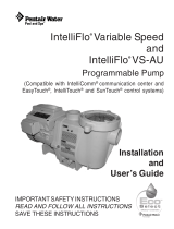
Pentair Variable Speed Programmable Pump User manual

Category
Above ground pool accessories
Type
User manual

Pentair Variable Speed Programmable Pump is a powerful and versatile device that can be used for various pool and spa applications. Its variable speed design allows for significant energy savings, and its simple, intuitive user interface makes it easy to program and operate. The pump also features a real-time clock with 24-hour memory retention and a removable strainer basket with built-in thermal overload protection. Additionally, the pump is totally enclosed and fan cooled for longer lifespan and quieter operation.

Pentair Variable Speed Programmable Pump is a powerful and versatile device that can be used for various pool and spa applications. Its variable speed design allows for significant energy savings, and its simple, intuitive user interface makes it easy to program and operate. The pump also features a real-time clock with 24-hour memory retention and a removable strainer basket with built-in thermal overload protection. Additionally, the pump is totally enclosed and fan cooled for longer lifespan and quieter operation.

Variable Speed
Programmable Pump
USER’S MANUAL
INSTALLATION | OPERATION | TROUBLE SHOOTING | PARTS
IMPORTANT SAFETY INSTRUCTIONS
READ AND FOLLOW ALL INSTRUCTIONS
SAVE THESE INSTRUCTIONS
1
READ CAREFULLY AND SAVE THIS INSTRUCTION MANUAL
TO USER/INSTALLER/OPERATOR – THIS USER MANUAL INCLUDES KEY POINTS AND
IMPORTANT SAFETY INSTRUCTIONS ON USING THIS PRODUCT, READ AND FOLLOW ALL
INSTRUCTIONS. FAILURE TO DO SO MAY RESULT IN SERIOUS INJURY OR DEATH. SAVE
THESE INSTRUCTIONS.
Read this "Safety Precautions" before operation.
Below information should not be neglected for proper use of this product. Follow all instructions can
help user avoid potential danger.
Following information is very important for safety in handling this product.
Be sure to observe them.
DANGER
Indicates an imminently hazardous situation which, if not avoided, will result in
death or serious injury.
WARNING
Indicates a potentially hazardous situation which, if not avoided, could result in
death or serious injury.
CAUTION
Indicates a potentially hazardous situation which, if not avoided, may result in
minor or moderate injury, or property damage.
IMPORTANT
PROHIBITED ALERT
DANGER
Stay off the main drain and away from all suction outlets.
strainer cover must be properly secured to prevent violent separation due to pressure in
the circulation system.
Before servicing, turn all the circulation system and pump controls off, make sure the
filter manual air relief valve is in the open position and all pressure is relieved.
It is highly recommend that this product be installed and serviced by a qualified pool
professional.
SAFETY PRECAUTION
2
WARNING
Remove plugs of the pool/spa from the suction outlets so as to void potential for suction
entrapment.
To reduce the risk of injury, do not permit children to use this product unless they are
closely supervised at all times.
Before starting, all system valves must be in a position that will allow pool water to
return back to the pool.
Make sure all components of the circulation system are in good condition and
assembled properly before operating the circulation system.
Before working on any electrical equipment, turn off power supply to the equipment.
Risk of Electric Shock. Connect only to a branch circuit protected by a ground-fault
circuitinterrupter (GFCI). Contact a qualified electrician if you cannot verify that the
circuit is protected by a GFCI.
The unit must be connected only to a supply circuit that is protected by a ground-fault
circuit-interrupter (GFCI). Such a GFCI should be provided by the installer and should
be tested on a routine basis. To test the GFCI, push the test button. The GFCI should
interrupt power. Push the reset button. Power should be restored. If the GFCI fails to
operate in this manner, the GFCI is defective. If the GFCI interrupts power to the
pump without the test button being pushed, a ground current is flowing, indicating the
possibility of an electric shock. Do not use this pump. Disconnect the pump and have
the problem corrected by a qualified service representative before using.
To reduce the risk of electric shock replace damaged cord immediately.
CAUTION
All electrical wiring must be in conformance with local code and National Electric Code
(NEC).
Though this pump is designed for outdoor use, it is strongly advised to keep the pump
from direct sunlight for a longer lifespan.
Install this pump in a place with good drainage.
Make sure the surrounding of the pump is ventilated to reduce the probability of
overheating.
This pump is for use with permanently-installed pools and may also be used with hot
tubs and spas if so marked. Do not use with storable pools. A permanently-installed
pool is constructed in or on the ground or in a building such that it cannot be readily
disassembled for storage. A storable pool is constructed so that it is capable of being
readily disassembled for storage and reassembled to its original integrity.
Do not install this pump in a damp location.
Do not run pump dry. Fail to do so will damage the mechanical shaft seal and result in
leakage and flooding. Fill strainer housing with water before running the pump.
3
Variable speed pump is a good choice for your pool which helps to save power consumption
significantly.
This manual includes instruction of three models: A , B and C. It contains important information on
how to operate the pump safely, properly and most efficiently. Read carefully before installation and
always follow instructions.
Feature
Variable speed design makes it extremely energy saving.
Simple, intuitive user interface, easy to program and operate.
Real-time clock with 24-hour memory retention.
A revolutionized removable strainer basket with a built-in thermal overload protection.
Totally enclosed fan cooled (TEFC) motor.
Control Panel
Variable Frequency Driver
AC Power Connection Terminal
Pump Motor
Pump Body
C
B
A
4
Dimension
Input: 230 VAC, 50/60 Hz, P1-1500 Watts, P2-1150 Watts, single phase.
A
C
B
5
Performance Curve
B
A
C
6
INSTALLATION GUIDE
Before servicing, turn the power supply off and stop the system circulation, open the air relief
valve and release all the pressure.
WARNING: This product should be installed and serviced by a qualified pool professional.
Try to install this pump as close as possible to the swimming pool. Plumbings with less joint and elbow
pipes are better for good suction. It is highly recommended that locate the pump in a cool, dry place
without direct sunlight for a longer lifespan. Install pump on a firm level surface to meet all local and
national codes. Fix pump on the base with bolts to reduce vibration.
It is also highly recommended to install a check valve on the pipe near the inlet port of the pump, so
that no priming is required when pump restarts after that.
Warning: Prevent foreign matters from entering the pump through inlet, fail to do so will result in
damage to the pump.
Warning: Keep product away from Children.
Use Teflon tape on the thread before screw fittings to pump inlet and outlet ports so as to avoid
leakage. Do not over-tighten the fittings.
Wiring
If pump comes with a power cord & plug, no wiring needed. In some areas, power cord is not provided
due to the local electrical standards and pump should be wired according to local electrical standards
and regulations. For those pumps, follow the instructions below to wire them:
Take off the AC power connection terminal box cover, there are 5 screws inside the terminal box, the
screw
1should be connected to the ground wire, the screw
2and
3should be connected to
either of the two live wires. The screw
4and
5is not used.
Make sure that the electrical supply available is suitable for the motor’s voltage, phase, and cycle, and
that the wire size is adequate for the HP (kW) rating and distance from the power source.
Warning: All electrical wiring must be performed by a licensed electrician,
Warning: All electrical wiring must conform to local codes and NEC regulations.
Warning: Use copper conductors only.
5
2
1
3
4
7
Electrical Guidance for Single phase motors
Rated
Volts
Circuit Breaker
Amps
Branch Fusetron
Amps
Recommended
Wire Size 0-50’
KW
HP
0.37
0.5
115
15
15
No. 14
0.55
0.75
115
230
15
10
15
6.25
No. 14
No. 14
0.75
1
115
230
20
10
20
9
No. 12
No. 14
1.1
1.5
115
230
30
15
30
15
No. 10
No. 14
1.55
2
115
230
30
15
30
12
No. 10
No. 14
1.88
2.5
230
20
20
No. 12
Voltage from the power source must be in the range from 90% to 110% of the motor nameplate rated
voltage. Fail to do so will result in overload tripping and reduced component life.
Install, ground, bond, and wire motor in accordance with local or NEC requirements.
Ground the pump by connecting a grounding wire from the electrical service ground terminal to the
motor grounding screw.
Bond pump motor to pool structure. The means creating a electrical connection between the pump
and the pool system. This helps to prevent any potential hazards that could occur if there was an
electrical issue with the pump.
8
PRIMING
Fill strainer housing with water, make sure no air or water leaks from anywhere of the pump, keep the
operator at least 10ft away from the pump.
Turn on power and wait for the pump to prime, which may take several minutes until the strainer
housing is full of water, the prime time depends on the vertical and horizontal distance of the suction
pipe. Make sure all necessary valves are open and the circulation is free when pump is running.
If pump fails to prime within five minutes, stop it and check the problem. See troubleshooting.
SERVICING
Warning: Stop pump and release all pressure from the circulation system before servicing.
Clean the filter basket regularly to ensure adequate water flow.
Make sure the motor runs in a normal way without any noise or vibration or overheating.
If any problem found on the pump, see troubleshooting to find the problem and contact distributor to
get spare parts for replacement. See spare parts.
STORAGE
Keep pump from freeze in cold weather, please follow the instructions to drain the pump:
Make sure the water level is below the suction pipe the pool.
Remove the drain plug from pump strainer body as well as the pump lid.
Take off pump from the mounting pad and pour out the remaining water from the pump.
Assemble the strainer lid and drain plug back to the pump.
Keep pump in dry and ventilated place.
Warning: Turn off the power and release all pressure before draining the pump.
Warning: Do not pack the pump in a sealed bag to prevent metal components from rusting.
9
CONTROLLER OPERATION
Operator Control Panel
Controls and LEDs
11 button/LED: when in manual mode, button 1 means manual speed 1; When in schedule mode,
this button means cycle 1. The LED lights on means the pump is running at speed 1 in manual mode
or running at cycle 1 in schedule mode.
22 button/LED: when in manual mode, button 2 means manual speed 2; When in schedule mode,
this button means cycle 2. The LED lights on means the pump is running at speed 2 in manual mode
or running at cycle 2 in schedule mode.
33 button/LED: when in manual mode, button 3 means manual speed 3; When in schedule mode,
this button means cycle 3. The LED lights on means the pump is running at speed 3 in manual mode
or running at cycle 3 in schedule mode.
4Auto Start: if LED is on, pump will start running automatically when power is given. LED off means
disable.
5Anti button: antifreeze function on/off.
6Quick Set: set up for current mode.
7Inv: shows basic parameters.
8Enter: save the current value and come into next set up item in quick edit mode.
10
9Arrow/+/- buttons:
Left arrow: move cursor left one digit.
Right arrow: move cursor right one digit.
+: increase a digit.
-: decrease a digit.
10 Quick Clean: to run pump at a certain speed for a certain duration time. Speed and duration can be
preset by pressing “Quick Set” button when in quick clean mode.
11 Set Time: set local time for pump.
12 Start Stop: start or stop the pump. LED will turn off once speed reduces to 0.
13 Mode: switch among manual mode, schedule mode and external control mode(if there is).
14 LEDs:
On: indicates pump is power on.
Warning: LED is on if a warning condition is present.
Alarm: LED is on if an alarm condition occurs.
11
Operating Pump
This section describes how to operate the pump using the control panel buttons.
Start the pump
Make sure the pump is power on and the green “On” power LED is on.
Press the “Start Stop” button to start the pump.
Stop the pump
Press the “Start Stop” button to stop the pump.
Run pump at preset speeds
The variable speed pump is programmed with three default speeds of 750, 2500 and 3450 RPM. A
speed button(1, 2, 3) is assigned to each of the preset speeds as shown. Follow instructions to run the
pump at one of the preset speeds:
Make sure the pump is in manual mode by pressing the “Mode” button.
Press the Speed button (1, 2, 3) corresponding to the desired preset speed, the LED above the
Speed button will turn on as shown.
Press the “Start Stop” button, the pump will quickly ramp to the selected preset speed.
Adjust the pump speed
Press the “+” or “-” button to increase or decrease the value of speed, new value will be saved
automatically.
Run pump in schedule mode
Make sure the pump is in schedule mode by pressing the “Mode” button.
Pump will come into the proper cycle according to the current time, the LED above the Cycle
button will turn on to indicate the current cycle#.
Press the “Start Stop” button, the pump will quickly ramp to the preset speed of the current cycle.
12
Set schedule cycle 1-3
Factory settings:
Cycle#
Start Time (24-hours)
Stop Time (24-hours)
Speed (RPM)
1
06:00
09:59
1700
2
10:00
15:59
3000
3
16:00
05:59
1200
Program of each cycle is allowed:
Go to the schedule mode by pressing “Mode” button until the phrase “Schedule Cycle” appears on
the screen.
Press “Quick Set” button to go into the speed setting page of schedule cycle1.
Change the value of speed by pressing the arrow and “+”/”-” button.
Press “Enter” to save and go into start time setting page of schedule cycle1.
Change the value of start time by pressing the arrow and “+”/”-” button.
Press “Enter” to save and go into stop time setting page of schedule cycle1.
Change the value of stop time by pressing the arrow and “+”/”-” button.
Press “Enter” to go into the speed setting page of schedule cycle2.
Change the value of speed by pressing the arrow and “+”/”-” button.
Press “Enter” to save and go into start time setting page of schedule cycle2.
Change the value of start time by pressing the arrow and “+”/”-” button.
Press “Enter” to save and go into stop time setting page of schedule cycle2.
Change the value of stop time by pressing the arrow and “+”/”-” button.
Press “Enter” to go into the speed setting page of schedule cycle3.
Change the value of speed by pressing the arrow and “+”/”-” button.
Press “Enter” to save and go into start time setting page of schedule cycle3.
Change the value of start time by pressing the arrow and “+”/”-” button.
Press “Enter” to save and go into stop time setting page of schedule cycle3.
Change the value of stop time by pressing the arrow and “+”/”-” button.
Set time
Make sure the screen is in the home page.
Press “Set Time” button.
Change value of the clock by pressing the arrow and “+”/”-” button. Note: time unit is 24 hours.
Press “Enter” to save and go back to the home page.
Set quick clean
Factory set quick clean speed at 3450RPM with duration 5 hours. Follow the instruction below if any
value should be changed:
Make sure the screen is in the home page.
Press “Quick Clean” button and go into quick clean mode.
Press “Quick Set” button to go into clean speed setting page.
Change the value of clean speed by pressing the arrow and “+”/”-” button.
Press “Enter” to save and go into clean time (duration) setting page.
Change the value of clean time by pressing arrow button and “+”/”-” button.
Press “Enter” to save and go back to the home page.
13
Set antifreeze
Factory set antifreeze function enabled with speed 750RPM when temperature is below 4. Follow
the instruction below if any value should be changed:
Make sure the screen is in the home page.
Press “Anti” button and go into antifreeze information page.
Press “Quick Set” button to go into enable/disable setting.
Change the value to “OFF” to make it inactive or keep it “on” to make this function active.
Press “Enter” to save and go into antifreeze speed setting page.
Change the value of antifreeze speed by pressing arrow button and “+”/”-” button.
Press “Enter” to save and go into temperature setting page.
Change the value of temperature by pressing arrow button and “+”/”-” button.
Note: temperature unit is
Press “Enter” to save and go back to the home page.
Basic Parameters
Noise: noise is adjustable, the larger the noise value is, the more electric protection pump will
have.Factory set noise at 10, which meets the electrical leakage standard of most Countries and
Areas. Please DO NOT change it if unnecessary.
Pump Address: this is available only in pump with RS485 modbus connector.
Minimum Speed: this allows the minimum speed the pump can run. Factory set at 450RPM, follow
the instruction below to change it if necessary:
Make sure the screen is in the home page.
Press “Inv” button and the screen will show the current pump performance data.
Press “Quick Set” button and go into setting page.
Press “Enter” several times until “min-speed” is shown on the screen.
Change value of minimum speed by pressing arrow and “+”/”-” button.
Press “Enter” to save.
If no other change needed, press “Quick Set” button to go back to home page.
Maximum Speed: this allows the maximum speed the pump can run. Factory set at 3450RPM, follow
the instruction below to change it if necessary:
Make sure the screen is in the home page.
Press “Inv” button and the screen will show the current pump performance data.
Press “Quick Set” button and go into setting page.
Press “Enter” several times until “max-speed” is shown on the screen.
Change value of maximum speed by pressing arrow and “+”/”-” button.
Press “Enter” to save.
If no other change needed, press “Quick Set” button to go back to home page.
External Speed: this is available only on pump with RS485 modbus connector, not apply to all the
models.
Baudrate: this is available and useful only on pump with RS485 modbus connector, not apply to all
the models.
Parity: this is available and useful only on pump with RS485 modbus connector, not apply to all the
models.
14
Wait Time: this is available and useful only on pump with RS485 modbus connector, not apply to all
the models.
Accelerate Time: this is available and useful only on pump with RS485 modbus connector, not apply
to all the models.
Decelerate Time: this is available and useful only on pump with RS485 modbus connector, not apply
to all the models.
Electric Consumption: this is the accumulated energy consumption of the pump from the last restore
of factory settings to the current moment. It is normal if it is not 0 before user runs the pump, as each
pump is tested before leaving factory.
Restore Factory Settings: this allows user to delete all the settings of the pump and all data will be
restored to factory settings.
15
MAINTENANCE
This section describes how to service and maintain the pump.
Strainer basket
The strainer basket locates in the pump strainer and can be seen when look down into the pump lid. It
should be inspected and cleaned regularly(once a week is recommended) to keep the pump working
efficiently.
How to service the strainer basket:
Stop pump and turn off power supply.
Relieve pressure in the system.
Remove the pump lid.
Take out the strainer basket and remove all the debris. Note: if the basket is cracked, replace it.
Rinse out the basket.
Put the basket back to the pump strainer housing.
Fill the pump strainer housing with water up to the inlet port level.
Re-install the pump lid.
Pump Motor
Though pump is designed for outdoor use, it is highly recommended to place it in a ventilate shadow
and avoid direct sun light and rain.
Keep away from any foreign matter, dirt or moisture. If the motor is wet, dry it before running.
Storage
Dry the pump before storage.
Do not wrap motor and controller with plastic or other air tight materials during storage.
Warning: Do not service pump when plug in, fail to follow this may cause injury.
16
TROUBLE SHOOTING
ISSUE
POSSIBLE SOLUTION
MOTOR WILL NOT
START
Wrong wiring; Loose electrical connection; Open switches or relays; Tripped circuit breakers,
GFCI’s, or blown fuses. No power supply or improper power supply.
Open the motor back cover and rotate the shaft manually to make sure it is not trapped.
If pump connects to a timer, make sure it works.
MOTOR SHUTS
OFF
Improper wiring(wrong wiring size or extension cords); Loose connections.
Low voltage
Electrical overload.
Motor overheating due to damage in violent transportation
MOTOR HUMS BUT
DOES NOT START
Centrifugal switch stuck in OPEN position.
Trapped impeller or motor shaft.
PUMP WON’T
PRIME
Make sure pump strainer housing is filled with water. Check to see if strainer cover is sealed
properly without air leakage.
Make sure all necessary valves are in open position and the water can circulation freely.
Check to see if pump develops a vacuum, if so, there might be air leakage in the plumbing,
please further check each pipe and joint in the plumbing;
If pump does not develop any vacuum, please further check if there’s air leakage from the pump
lid or connectors/fittings. Also, make sure impeller is not trapped by debris.
LOW FLOW
The filter screen or suction pipe is blocked or restricted.
Pipe not big enough for more water to go through.
Filter pressure too high due to dirty filter media. If pump connects to a sand filter, backwash the
sand filter; If pump connects to a cartridge filter, replace the cartridge.
Leakage from the pump lid or connectors/fittings. If air leaks in suction pipe, pump will rumble
constantly.
Cavitation due to restricted or undersized suction line or leak at any joint, low water level in pool,
and unrestricted discharge return lines. Correct suction condition or throttle return lines, if
practical. Holding hand over return fitting will sometimes prove this point or putting in a smaller
eyeball fitting.
NOISY PUMP
Pump base vibration.
Foreign matters in the pump, especially around the impeller, try to remove the foreign matters
from the pump.
Motor bearings noisy from normal wear, rust, overheating, or concentration of chemicals
causing seal damage which will allow chlorinated water to seep into bearings wiping out the
grease causing bearing to whine. All seal leaks should be replaced at once.
17
REPLACEMENT PARTS
No.
Description
A-1
Lid & Clamp Ring
A-2
O-Ring
A-3
Basket
A-4
Strainer Casing
A-5
Drain Plug
A-6
Diffuser O-Ring
A-7
Diffuser
A-8
Impeller
A-9
Pump Casing O-Ring
A-10
Pump Housing
A-11
Screw
A-12
Motor
A-13
Carrier
A-14
Shaft Seal
A-15
Controller
18
No.
Description
B-1
Lid
B-2
O-ring
B-3
Basket
B-4
Strainer Casing
B-5
Diffuser O-ring
B-6
Impeller Cover
B-7
Diffuser
B-8
Impeller
B-9
Shaft Seal
B-10
Pump Housing O-ring
B-11
Pump Housing
B-12
Pump Cover
B-13
Screw
B-14
Variable Speed Motor
B-15
Screw
B-16
Drain Plug
B-17
Carrier
B-18
Lid Removal Tool
19
No.
Description
C-1
Lid
C-2
O-ring
C-3
Basket
C-4
Strainer Casing
C-5
Drain Plug
C-6
Diffuser O-ring
C-7
Diffuser
C-8
Impeller
C-9
Pump Housing O-ring
C-10
Pump Housing
C-11
Pump Housing Screw
C-12
Variable Speed Motor
C-13
Motor Screw
C-14
Carrier
C-15
Shaft Seal
C-16
Flange
C-17
Carrier Screw
C-18
Diffuser Screw
  • Page 1 1
  • Page 2 2
  • Page 3 3
  • Page 4 4
  • Page 5 5
  • Page 6 6
  • Page 7 7
  • Page 8 8
  • Page 9 9
  • Page 10 10
  • Page 11 11
  • Page 12 12
  • Page 13 13
  • Page 14 14
  • Page 15 15
  • Page 16 16
  • Page 17 17
  • Page 18 18
  • Page 19 19
  • Page 20 20

Pentair Variable Speed Programmable Pump User manual

Category
Above ground pool accessories
Type
User manual

Pentair Variable Speed Programmable Pump is a powerful and versatile device that can be used for various pool and spa applications. Its variable speed design allows for significant energy savings, and its simple, intuitive user interface makes it easy to program and operate. The pump also features a real-time clock with 24-hour memory retention and a removable strainer basket with built-in thermal overload protection. Additionally, the pump is totally enclosed and fan cooled for longer lifespan and quieter operation.

Ask a question and I''ll find the answer in the document

Finding information in a document is now easier with AI