Bosch dhi965v Owner's manual

Category
Cooker hoods
Type
Owner's manual
19
Operating modes
This can be achieved if the combustion air
is able to flow through non-lockable
openings, e.g. in doors, windows and in
conjunction with an air supply/air-intake wall
box or by other technical procedures such
as reciprocal interlocking.
If the air intake is inadequate, there is a
risk of poisoning from combustion gases
which are drawn back into the room.
An air-intake/exhaust-air wall box by itself is
no guarantee that the limiting value will not
be exceeded.
Note: When assessing the overall
requirement, the combined ventilation
system for the entire household must be
taken into consideration. This rule does not
apply to the use of cooking appliances,
such as hobs and ovens.
Unrestricted operation is possible if the
extractor hood is used in recirculating mode
– with activated carbon filter.
Circulating-air mode:
An activated carbon filter must be fitted
for this operating mode (see Filters and
maintenance).
The complete installation set and
replacement filters can be obtained from
specialist outlets.
The corresponding accessory numbers
can be found at the end of these
operating instructions.
The extractor-hood fan extracts the
kitchen vapours which are purified in the
grease filter and activated carbon filter
and then conveyed back into the
kitchen.
The grease filter absorbs the grease
particles in the kitchen vapours.
The activated carbon filter binds the
odorous substances.
If no activated carbon filter is installed,
it is not possible to bind the odorous
substances in the cooking vapours.
Light / fan switches Filter drawer
Description of appliance
Operating instructions:
Operating modes
Exhaust-air mode:
The extractor-hood fan extracts the
kitchen vapours and conveys them
through the grease filter into the
atmosphere.
The grease filter absorbs the solid
particles in the kitchen vapours.
The kitchen is kept almost free of grease
and odours.
D
If the extractor hood is operated in
exhaust-air mode at the same time as a
flue-type heater (e.g. gas, oil or solid-fuel
heater, instantaneous water heater, boiler),
ensure that there is an adequate air
supply which the heater requires for
combustion.
Safe operation is possible provided that the
partial vacuum in the room in which the
heater is installed does not exceed 4 Pa
(0.04 mbar).
20
Before using for the first time
Important notes:
The Instructions for Use apply to several
versions of this appliance. Accordingly,
you may find descriptions of individual
features that do not apply to your
specific appliance.
This extractor hood complies with all
relevant safety regulations.
Repairs should be carried out by
qualified technicians only.
Improper repairs may put the user at
considerable risk.
Do not flambé food directly under the
extractor hood.
Risk of grease filter catching fire due
! to flames.
Restrictions apply to the use of the
extractor hood over a solid-fuel burner
(coal, wood, etc.). (See Installation
instructions).
Gas hobs / gas cookers
Always use gas hobs in a proper and
safe manner.
Important:
The flames from the gas hob must always
be covered by pots or pans.
The intense heat generated by the gas
flames could cause damage to the
! extractor hood.
Before using your appliance for the first
time, please read these Instructions for
Use carefully. They contain important
information concerning your personal
safety as well as on use and care of the
appliance.
Please retain the operating and
installation instructions for a subsequent
owner.
Do not use the appliance if damaged.
The appliance is not intended for use
by young children or infirmed persons
without supervision.
Young children should be supervised to
ensure they do not play with the appliance.
If the connecting cable for this
appliance is damaged, the cable must be
replaced by the manufacturer or his
customer service or a similarly qualified
person in order to prevent serious injury to
the user.
The appliance may be connected to
the mains by a qualified technician only.
Dispose of packaging materials
properly (see Installation instructions).
Light bulbs must always be fitted when
the extractor hood is in use.
Defective bulbs should be replaced
immediately to prevent the remaining bulbs
from overloading.
Never operate the extractor hood
without a grease filter.
Overheated fat or oil can easily catch
fire.
If you are cooking with fat or oil, e.g. chips,
etc., never leave the cooker unattended.
21
Intermittent ventilation
Used for ventilating the kitchen at hourly
intervals at the lowest fan setting, round
the clock.
Switching on appliance:
Press the button and insert the filter
drawer.
The fan runs for 5 minutes at Setting |,
then switches off for 55 minutes. This
process is repeated every hour.
Switching off:
Press the button.
Operating the extractor hood
Intermittent
ventilation
Light
on / off
Display:
Fan settings / Intensive
setting
ç
Saturation – grease filter #
Saturation –
activated carbon filter
ã
Fan
on / off
The most effective method of removing
vapours produced during cooking is to:
Switch the ventilator ON
as soon as you begin cooking.
Switch the ventilator OFF
a few minutes after you have finished
cooking.
Switching on appliance:
Press the
L or + button.
The fan starts at Setting
}.
Fan – off –
Fan settings
– lower –
Fan – on –
Fan settings
– higher –
1. To increase the fan settings or switch on
the intensive setting
ç
, press the +
button.
The intensive setting operates at
maximum power which should be
used only briefly.
If the intensive setting is not switched
off manually, the fan automatically
switches back to Setting
} after
10 minutes.
2. To switch off the intensive setting
ç or
switch back to fan settings
~ } |
and
switch off the extractor hood
completely, press the
button.
Switching on the fan settings/intensive
setting:
22
Operating the extractor hood
Switching off:
There are 2 different ways of switching off
the appliance.
Switching off directly:
Press the
L button.
Important: All fan functions are switched
off.
Switching off appliance with fan run-on:
Insert filter drawer all the way. The fans
operate in the last switched-on stage for
around another 10 minutes and then switch
off.
If the intensive setting is switched on
when the filter drawer is inserted, the
intensive setting automatically switches
back during run-on.
If intermittent ventilation is switched on, it
continues operating normally following
run-on.
Light
The light can be used at any time, even
when the appliance has been switched
off.
Switching on/off: Press the
a button.
Adjusting the brightness:
Hold down the a button until the
desired brightness is obtained.
After approx. 3 seconds the light
switches on to acknowledge the setting.
Switching off:
Repeat the process with the light switched
on.
After approx. 3 seconds the light
switches off to acknowledge the setting.
Special functions
Switching on the light automatically, e.g.
via a timer:
Fan and light must be switched off.
Switching on:
Simultaneously press the and
buttons.
23
Removing and inserting the metal-mesh
grease filters:
Warning: The halogen bulbs must be
switched off and cool.
1. Pull the filter drawer all the way out.
2. Depress the catches at the rear of the
grease filter and remove the grease filter.
4. Clean the filters.
5. Insert the clean filters back into the hood.
6. Cancel the
# display.
Press the
L button for at least
3 seconds.
The
# display then goes out.
3. Depress both catches at the front of the
grease filter and remove the grease filter.
Grease filters:
Metal-mesh filters are used to trap the
grease particles in the cooking vapours.
The filter mats are made from non-
combustible metal.
Caution:
As the filter becomes more and more satu-
rated with grease, there is an increased risk
of fire and the function of the extractor
hood may be impaired.
Important:
By cleaning the metal grease filters at
appropriate intervals, the possibility of them
catching fire as a result of a build-up of heat
such as occurs when deep-fat frying or
roasting is taking place, is reduced.
Saturation indicator:
When the grease filters reach saturation
point, an acoustic signal is sounded for 6
seconds after the fan has switched off, and
an
#
appears in the display. The grease
filters should be cleaned straight away.
Cleaning the metal-mesh grease filters:
The filters can be cleaned in a
dishwasher. However, they may become
slightly discoloured.
Important:
Do not wash highly saturated metal-
mesh grease filters with other utensils.
If cleaning the filters by hand, soak them in
a hot soap solution. Then brush the filters,
rinse thoroughly and leave to drain.
Clean the support frame for the grease
filters by hand.
Filters and maintenance
24
Removing the filter:
Warning: The halogen bulbs must be
switched off and cool.
1. Remove the metal-mesh filters.
2. Depress the catches on both sides of
the filter and remove the activated
carbon filter.
3. Replacing the activated carbon filter:
A replacement filter can be obtained
from any authorized dealer
(see optional accessories).
Use original filters only.
This will ensure maximum
performance.
4. Insert the grease filters.
Disposing of the old activated carbon
filter:
Activated carbon filters do not contain
any pollutants and can be disposed of
with domestic refuse.
Filters and maintenance
3. Engage the catches at both sides.
4. Insert the metal-mesh grease filters (see
”Removing and inserting the metal-mesh
grease filters”).
5. Cancel the
ã display.
Press the
L button for at least
3 seconds.
The
ãdisplay then goes out.
Saturation indicator:
When the activated carbon filter is satura-
ted, an acoustic signal is emitted for 6
seconds when the fan has switched off and
ã
is displayed. The activated carbon filter
should then be replaced immediately.
Activated carbon filter:
For neutralizing odours in recirculating
mode.
Caution:
As the filter becomes more and more
saturated with grease, there is an increased
risk of fire and the function of the extractor
hood may be impaired.
Important:
Change the activated carbon filter promptly
to prevent the risk of fire from the
accumulation of heat when deep-fat frying
or roasting.
Inserting the filter:
Warning: The halogen bulbs must be
switched off and cool.
1. Remove the metal filters
(see "Removing and inserting the metal
grease filters").
2. Insert the activated carbon filter.
25
Cleaning and care
Isolate the extractor hood by pulling out
the mains plug or switching off the fuse.
When cleaning the grease filters, remove
grease deposits from accessible parts of
the housing. This prevents the risk of fire
and ensures that the extractor hood
continues operating at maximum
efficiency.
Clean the extractor hood with a hot soap
solution or a mild window cleaner.
Do not scrape off dried-on dirt but wipe
off with a damp cloth.
Do not use scouring agents or abrasive
sponges.
Note: Do not use alcohol (spirit) on
plastic surfaces, as dull marks may
appear.
Caution: Ensure that the kitchen is ade-
quately ventilated. Avoid naked flames!
Clean the operating buttons with a mild
soapy solution and a soft, damp cloth only.
Do not use stainless-steel cleaner to clean
the operating buttons.
Stainless steel surfaces:
Use a mild non-abrasive stainless steel
cleaner.
Clean the surface in the same direction
as it has been ground and polished.
Do not use any of the following to clean
stainless steel surfaces: abrasive sponges,
cleaning agents containing sand, soda, acid
or chloride!
Aluminium and plastic surfaces:
Use a soft, non-linting window cloth or
micro-fibre cloth.
Do not use dry cloths.
Use a mild window cleaning agent.
Do not use aggressive, acidic or caustic
cleaners.
Do not use abrasive agents.
4. Re-insert the bulb ring.
5. Restore the power by inserting the mains
plug or switching on the fuse.
Note: If the light does not function, check
that the bulbs have been inserted correctly.
Replacing the light bulbs
1. Switch off the extractor hood and pull
out the mains plug or switch off the
electricity supply at the fuse box.
When switched on, the halogen bulbs
become very hot. Even for some time after
the bulbs have been switched off there is
still a risk of burns.
2. Remove the bulb ring with a screwdriver
or similar tool.
3. Replace the halogen light bulb
(conventional halogen bulb, 12 Volt,
max. 20 Watt, G4 bulbholder).
Caution: Plug-in bulbholder.
Take hold of the bulb with a clean cloth.
26
You can move the operating unit from
the middle of the filter drawer to the left
or right side.
The operating unit can also be fitted at the
front in a handle moulding available as an
optional accessory or in the enclosed
handle moulding (see optional accessories
on back page).
Moving the operating unit
1. Loosen the 2 screws from below.
2. Remove the operating unit and dis-
connect the plug from the ribbon cable.
3. Remove the side cover from the filter
drawer.
4. Connect the plug of the side ribbon
cable to the operating unit.
5. Insert the operating unit into the side of
the filter drawer.
Insert the excess ribbon cable.
6. Insert the cover into the middle of the
filter drawer and screw on the cover from
below with 2 screws.
Setting the saturation indicator
If the operating mode is to be switched
over (exhaust air/circulating air mode), the
saturation indicator for the filters must also
be switched over (see Installation
instructions).
Faults
If
#
or
ã
is displayed:
See "Filters and maintenance" Section.
If the extractor hood cannot be
operated:
Isolate the extractor hood for approx.
1 minute by pulling out the mains plug or
switching off the fuse.
Then switch on again..
If you have any questions or if a fault
occurs, please call Customer Service.
(See list of Customer Service
representatives).
When you call, please quote the following:
E-Nr. FD
Enter the numbers in the above box. The
numbers can be found on the rating plate
inside the extractor hood following removal
of the grease filters.
27
Important information
Installation Instructions:
The installation of the extractor hood
above gas cooking devices, at a
minimum height of 650 mm – Fig. 1 – is
permitted provided that the following
nominal heat loads (Hs) are not exceeded:
Gas cookers
Load of one hotplate max. 03.0 kW
Load of all hotplates max. 08.3 kW
Load of the oven max. 03.9 kW
Gas hobs
Load of one hotplate max. 03.9 kW
Load of all hotplates max. 11.3 kW
Gas ceramic hotplate
The nominal heat load specifications do
not apply to closed gas ceramic hobs.
Always observe the specifications of the
hob manufacturer.
Solid-fuel cookers
The maximum nominal heat loads and
the minimum distance are the same as
for gas cookers.
The extractor hood must not be
installed over a solid fuel cooker – a
potential fire hazard (e.g. flying sparks) –
unless the cooker features a closed,
non-removable cover and all national
regulations are observed.
The smaller the gap between the
extractor hood and hotplates, the greater
the likelihood that droplets will form on the
underside of the extractor hood.
Old appliances are not worthless
rubbish. Valuable raw materials can be
reclaimed by recycling old appliances.
Before disposing of your old appliance,
render it unusable.
You received your new appliance in a
protective shipping carton. All packaging
materials are environmentally friendly and
recyclable. Please contribute to a better
environment by disposing of packaging
materials in an environmentally-friendly
manner.
Please ask your dealer or inquire at your
local authority about current means of
disposal.
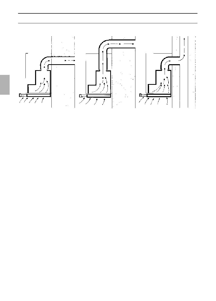
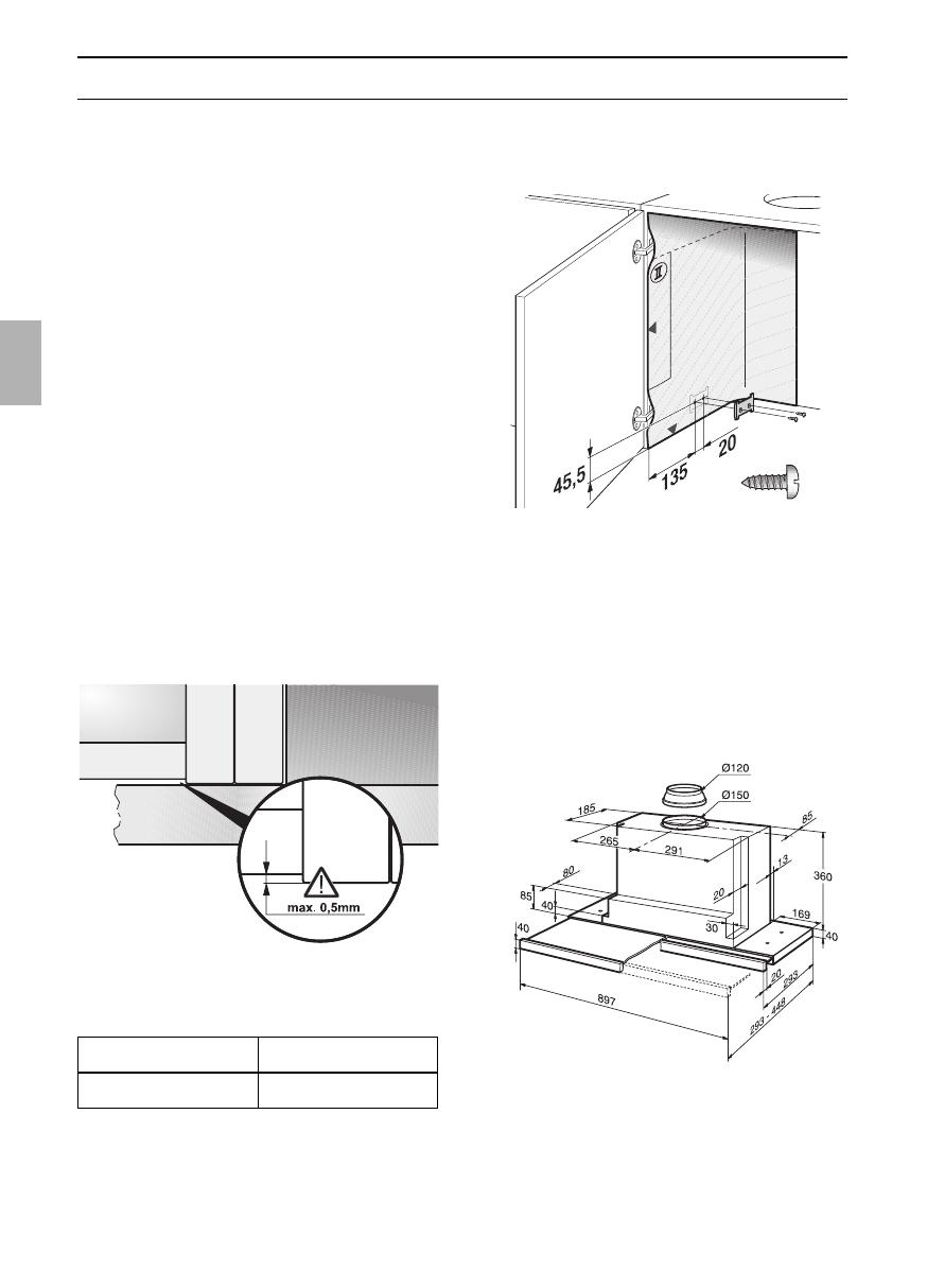
The extractor hood can be used in
exhaust air or circulating air mode.
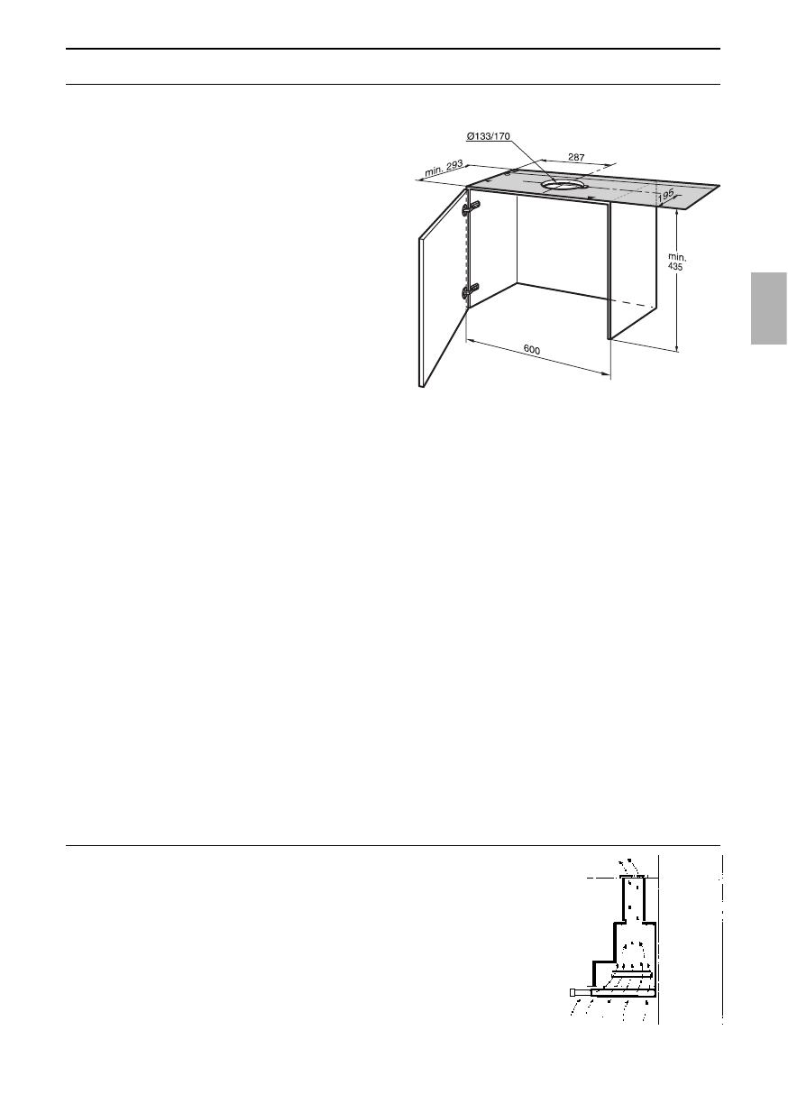
Always mount the extractor hood over
the centre of the hob.
Minimum distance between electric
hob and bottom edge of extractor hood:
430 mm, Fig. 1.
Additional information concerning gas
cookers:
When installing gas hotplates, comply
with the relevant national statutory
regulations (e.g. in Germany: Technische
Regeln Gasinstallation TRGI).
Always comply with the currently valid
regulations and installation instructions
supplied by the gas appliance
manufacturer.
Only one side of the extractor hood
may be installed next to a high-sided unit
or high wall. Gap at least 300 mm.
28
Prior to installation
Exhaust-air mode
The exhaust air is discharged upwards
through a ventilation shaft or directly
through the outside wall into the open.
D
Exhaust air must not be discharged via
a smoke or exhaust gas flue which is
already in use or via a shaft which is used
for ventilating rooms in which fireplaces are
located.
Discharge exhaust air in accordance
with official and statutory regulations
(e.g. national building regulations).
Discharge of air into smoke or exhaust air
flues which are not in use requires the
consent of a heating engineer.
D
If the extractor hood is operated in
exhaust-air mode at the same time as a
flue-type heater (e.g. gas, oil or solid-fuel
heater, instantaneous water heater, boiler),
ensure that there is an adequate air
supply which the heater requires for
combustion.
Safe operation is possible provided that the
partial vacuum in the room in which the
heater is installed does not exceed 4 Pa
(0.04 mbar).
This can be achieved if the combustion air
is able to flow through non-lockable
openings, e.g. in doors, windows and in
conjunction with an air supply/air-intake wall
box or by other technical procedures such
as reciprocal interlocking.
If the air intake is inadequate, there is a
risk of poisoning from combustion gases
which are drawn back into the room.
An air-intake/exhaust-air wall box by itself is
no guarantee that the limiting value will not
be exceeded.
Note: When assessing the overall
requirement, the combined ventilation
system for the entire household must be
taken into consideration. This rule does not
apply to the use of cooking appliances,
such as hobs and gas cookers.
The extractor hood can be used without
restriction in circulating air mode – with an
activated carbon filter.
For exhaust air mode a one-way flap
should be installed in the extractor hood
unless already installed in the exhaust air
pipe or wall box.
If a one-way flap is not enclosed with the
extractor hood, you purchase one from
your dealer.
If the exhaust air is conveyed through
the outside wall, a telescopic wall box
should be used.
Before installation
Optimum efficiency of the extractor
hood:
Short, smooth exhaust pipe.
As few bends as possible.
Pipe diameter as large as possible
(ideally 150 mm dia.) and wide pipe
bends.
If long, rough exhaust-air pipes,
many pipe bends or smaller pipe
diameters are used, the air extraction
rate will no longer be at an optimum
level and there will be an increase in
noise.
Round pipes
Short exhaust air pipe:
inside diameter min. 120 mm,
Longer exhaust air pipe:
inside diameter min. 150 mm.
Flat ducts must have an inside
cross-section equivalent to that of the
round pipes.
There should be no sharp bends.
l 120 mm dia. approx. 113 cm
2
l 150 mm dia. approx. 177 cm
2
If pipe diameters differ, insert sealing
strip.
Ensure that there is an adequate air
supply for exhaust air mode.
Exhaust air directed backwards:
Only possible inside tall wall cupboards
depending on the size of the exhaust air
pipe.
Make a hole in the rear panel of the wall
cupboard, cutting out a notch for the
power supply cable.
Circulating-air mode
With activated carbon filter if exhaust-air
mode is not possible.
Exhaust air directed upwards:
The complete
installation set can
be obtained from
specialist outlets.
The corresponding
accessory numbers
can be found at the
end of these opera-
ting instructions.
1. Make a hole in the top of the wall cupbo-
ard, cutting out a notch for the power
supply cable.
– template
O
I enclosed –.
2. If fitted, cut out the cupboard base to a
min. depth of 270 mm over the entire
width.
Note:
An installation kit is required if the width
of the cupboard is 900 mm.
Connecting a 150 mm exhaust pipe:
Attach the exhaust pipe directly to the air
connector.
Connection of 120 mm l exhaust air
pipe:
Attach enclosed reducing connector to
the air outlet.
Holes in the air outlet must be sealed.
Attach exhaust air pipe to the reducing
connector.
29
30
Preparing the wall cupboard
1. Mark two attachment points on both the
right and left inside faces of the cup-
board and make holes with a bradawl.
When you drill:
2 mm diameter – max. 10 mm in depth.
Use the enclosed template
O
II to mark
the attachment points.
2. Screw on both attachment plates.
3. Attach the door to the cupboard and
align.
Observe the minimum distance
between hotplates and extractor hood!
Fig. 1.
This extractor hood is designed to be
installed in a wall cupboard with the follo-
wing dimensions:
width: 600 mm
depth: 293 to 350 mm
height: min. 435 mm.
If the cupboard is deeper than 293 mm,
the extractor hood can be moved back,
e.g. to put a spice rack in front of the
extractor hood.
To do this, place the template
O
II further
back.
Ensure that the cupboard is stable both
during and after installation, even if fitted at
the end of a row of kitchen units.
Do not install the extractor hood at the
end of the kitchen line.
Align the cupboards exactly. If required,
place the side cupboards flush underneath.
The side panels must not project over
the base of the adjacent unit by more than
0.5 mm.
Exhaust air Circulating air
16,0 16,5
We reserve the right to construction changes within the
context of technical development.
Weight in kg:
3. Screw in the adjusting screws by hand
until the extractor hood is situated on
the base of the cupboard.
7. Feed the mains connection cable out of
the cupboard.
8. Connect the pipes in the wall cupboard.
– If required, attach the air hose to the
cupboard ceiling –.
9. Re-insert grease filter
(see Operating instructions).
Fitting into wall cupboard
Check door alignment and readjust if
necessary.
1. Remove grease filter
(see Operating instructions).
2. Lift the extractor hood into the cupboard
from below until both fixing lugs have
locked firmly into position.
Align the extractor hood in the
cupboard.
Carefully tighten both fastening screws.
4. Also attach the extractor hood to the left
and right wall cupboards with 2 screws
each side. First make pilot holes with a
bradawl.
5. Seal the holes with 2 stoppers each on
the left and right.
6. If required, shorten the wall cover to the
required dimension (e.g. saw off).
Attach the wall cover with the enclosed
clips.
Screw the wall cover to the wall
cupboard.
31
32
Fitting into wall cupboard
Note: The extractor hood housing can be
clad inside the wall cupboard (e.g. with
chipboard).
If so, observe the following:
The intermediate base must not be
placed on the extractor hood housing.
Never attach cladding to the housing.
Provide access for customer service.
If the extractor hood is to be installed
further back in the cupboard, the stops
for the filter drawer can be moved
forwards.
To do this, undo the screws, move the
stops and retighten the screws.
Re-adjusting the limit switch:
1. Check whether the extractor hood
switches off when the filter drawer is
inserted.
2. If the extractor hood does not switch off,
re-adjust the limit switch.
3. Unscrew the screw in small steps –
max. 2 revolutions.
2. Align handle
moulding
and screw
to the
appliance.
Do not
pinch the ribbon
cable.
Moving the operating unit:
See Operating instructions.
Attaching the handle moulding:
A handle moulding must be attached to
the filter drawer.
This handle moulding may be a wooden
strip which matches the kitchen units or a
handle moulding available as an optional
accessory (see optional accessories on the
back page).
1. Using the enclosed template
O
III , mark
the attachment points on the wooden
strip and make holes with a bradawl.
When you drill:
2 mm dia – max. 10 mm in depth.
33
1. Disconnect from power.
2. Disconnect pipes.
3. Remove filters.
4. Undo right and left fixing screws until the
extractor hood cannot drop any further.
5. Raise the extractor hood briefly until the
fixing lugs detach and the appliance can
be lowered.
Fastening screws may project.
When raising the extractor hood, do not
force in the filter drawer.
6. Preparing for re-installation:
Screw in the left and right fixing screws
until the lugs are pressed out at the
sides.
Electrical connection
WARNING: THIS APPLIANCE MUST BE
EARTHED
IMPORTANT: Fitting a Different Plug:
The wires in the power cord are colour-
coded as follows:
Green and Yellow Earth
Blue Neutral
Brown Live
If you fit your own plug, the colours of
these wires may not correspond with the
identifying marks on the plug terminals.
Proceed as follows:
1. Connect the green and yellow (Earth)
wire to the terminal in the plug marked
‘E’ or with the symbol ( ), or
coloured green or green and yellow.
2. Connect the blue (Neutral) wire to the
terminal in the plug marked ‘N’ or
coloured black.
3. Connect the brown (Live) wire to the
terminal marked ‘L’, or coloured red.
The extractor hood may be connected to
a correctly installed earthed socket only.
Attach the earthed socket near the
extractor hood in an accessible position.
The earthed socket should be
connected via its own power circuit.
If appliances do not feature the OFF
delay function, the indicator may start flas-
hing when the extractor hood has been
switched off for several hours via a separa-
te switch, even though the grease filters are
not yet saturated.
(See instructions for use, section on filter
and maintenance).
Electrical specifications:
These can be found on the rating plate
inside the appliance following removal of
the filter frames.
Before carrying out repairs, always
isolate the appliance.
Length of the connection cable: 1.30 m.
If permanent connection is required:
The extractor hood may only be connected
by an electrician registered with the local
electricity board.
A disconnecting device must be provided
on the installation side. Switches with a
contact opening of more than 3 mm and
all-pole disconnection are regarded as
disconnecting devices. These include LS
switches and contactors.
This extractor hood complies with EU
regulations on interference suppression.
Removal from the wall
cupboard
Do not lift the
extractor hood
when undoing the
fixing screws.
34
Switching over from exhaust air to circulating air mode
Switching the electronic control system
to circulating air mode:
The extractor hood has been set to
exhaust air mode at the factory.
Before the mode can be changed, the
extractor hood must have been
connected and should be switched off.
1. Press and hold down the L button.
2. Press the button for approx.
3 seconds.
A
ã is displayed.
3. Release the buttons.
The display goes out shortly
afterwards.
Resetting to exhaust-air mode:
1. Repeat the procedure.
A
# is displayed.
2. Release the buttons.
The display goes out shortly
afterwards.
5750 204 893
Printed in Germany 0704 Es.
Robert Bosch Hausgeräte GmbH
  • Page 1 1
  • Page 2 2
  • Page 3 3
  • Page 4 4
  • Page 5 5
  • Page 6 6
  • Page 7 7
  • Page 8 8
  • Page 9 9
  • Page 10 10
  • Page 11 11
  • Page 12 12
  • Page 13 13
  • Page 14 14
  • Page 15 15
  • Page 16 16
  • Page 17 17
  • Page 18 18
  • Page 19 19
  • Page 20 20
  • Page 21 21
  • Page 22 22
  • Page 23 23
  • Page 24 24
  • Page 25 25
  • Page 26 26
  • Page 27 27
  • Page 28 28
  • Page 29 29
  • Page 30 30
  • Page 31 31
  • Page 32 32
  • Page 33 33
  • Page 34 34
  • Page 35 35
  • Page 36 36
  • Page 37 37
  • Page 38 38
  • Page 39 39
  • Page 40 40
  • Page 41 41
  • Page 42 42
  • Page 43 43
  • Page 44 44
  • Page 45 45
  • Page 46 46
  • Page 47 47
  • Page 48 48
  • Page 49 49
  • Page 50 50
  • Page 51 51
  • Page 52 52
  • Page 53 53
  • Page 54 54
  • Page 55 55
  • Page 56 56
  • Page 57 57
  • Page 58 58
  • Page 59 59
  • Page 60 60
  • Page 61 61
  • Page 62 62
  • Page 63 63
  • Page 64 64
  • Page 65 65
  • Page 66 66
  • Page 67 67
  • Page 68 68
  • Page 69 69
  • Page 70 70
  • Page 71 71
  • Page 72 72
  • Page 73 73
  • Page 74 74
  • Page 75 75
  • Page 76 76
  • Page 77 77
  • Page 78 78
  • Page 79 79
  • Page 80 80
  • Page 81 81
  • Page 82 82
  • Page 83 83
  • Page 84 84
  • Page 85 85
  • Page 86 86
  • Page 87 87
  • Page 88 88
  • Page 89 89
  • Page 90 90
  • Page 91 91
  • Page 92 92
  • Page 93 93
  • Page 94 94
  • Page 95 95
  • Page 96 96
  • Page 97 97
  • Page 98 98
  • Page 99 99
  • Page 100 100
  • Page 101 101
  • Page 102 102
  • Page 103 103
  • Page 104 104
  • Page 105 105
  • Page 106 106
  • Page 107 107
  • Page 108 108
  • Page 109 109
  • Page 110 110
  • Page 111 111
  • Page 112 112
  • Page 113 113
  • Page 114 114
  • Page 115 115
  • Page 116 116

Bosch dhi965v Owner's manual

Category
Cooker hoods
Type
Owner's manual

Ask a question and I''ll find the answer in the document

Finding information in a document is now easier with AI