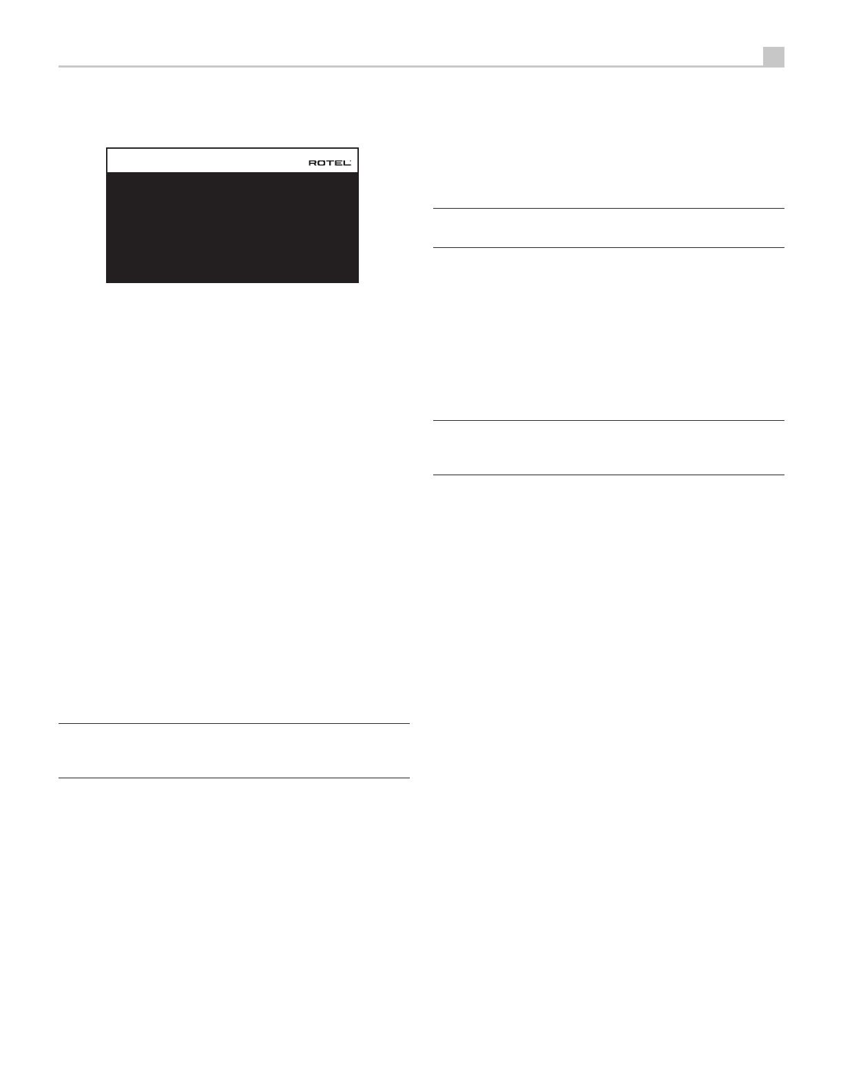
Rotel RSP-1576 Owner's manual

Type
Owner's manual
STANDBYSTANDBY
RSP-1576
HDMI
MUTE
2CH SUR + DISPLAYBYPASS
VIDEO 1 VIDEO 2 VIDEO 3 VIDEO 4 VIDEO 5 VIDEO 6 VIDEO 7
USB PC-USB XLR TUNER CD PHONO BT
5V 2.1A
Owner’s Manual
Manuel de l’utilisateur
Bedienungsanleitung
Manual de Instrucciones
Gebruikershandleiding
Manuale di istruzioni
Bruksanvisning
Инструкция пользователя
RSP-1576
Surround Sound Processor
Processeur Audio Surround
Surround-Prozessor
Procesador de Sonido Envolvente
Surround sound-processor
Processore Surround
Surroundprocessor
Процессор окружающего звука
2
RSP-1576 Surround Sound Processor
Remote Control Overview ...........................................18
Overview of Buttons and Controls .....................................18
STANDBY 1 and Power ON/OFF Buttons A 18
VOLUME Knob and VOLUME UP/DOWN Buttons =D 18
DISPLAY (DISP) Button 0B 18
SETUP Button H 18
Navigation and ENTER Buttons I 18
MUTE Button -F 18
Input Buttons 4qM 18
SUR+ Buttons 9B 18
Playback Control buttons L 18
DIM Button J 18
SUB, CTR, REAR Buttons B 18
MEM Button E 18
LIGHT Button N 18
ASSISTIVE LIGHT O 18
Automatic Surround Modes ...........................................18
Manually Selecting Surround Modes ....................................19
Digital Audio 19
Analog Stereo 19
Basic Operation ...................................................19
Selecting Inputs 19
USB/iPod Operation ...............................................20
iPod/iPhone Connection 0 20
Playback Control Buttons L 20
Bluetooth. . . . . . . . . . . . . . . . . . . . . . . . . . . . . . . . . . . . . . . . . . . . . . . . . . . . . . . . 20
Bluetooth Connection 20
Rear PC-USB .....................................................20
Rear PC-USB Connection 20
Setup ..........................................................20
Menu Basics. . . . . . . . . . . . . . . . . . . . . . . . . . . . . . . . . . . . . . . . . . . . . . . . . . . . . . 20
Navigation Buttons 20
Main Menu 20
Configuring Inputs .................................................20
Input Setup 21
Multi Input Setup 22
Configuring Audio ..................................................22
Audio Conguration 22
Configuring Speakers and Audio .......................................22
Speaker Conguration 22
Advanced Speaker Setup 23
Subwoofer Setup 24
Speaker Level Setup 24
Speaker and Delay/Distance Setup 25
Miscellaneous Settings ..............................................25
System Setup 25
Video Setup 26
PEQ Conguration 27
Troubleshooting ...................................................27
Specications .....................................................28
Contents
Important Safety Instructions ..........................................4
Figure 1: Control and Connections 5
Figure 2: Remote Control 6
Figure 3: Amplier And Subwoofer 7
Figure 4: Digital Audio and PC-USB Connections 8
Figure 5: Blu-Ray and Video Player Connections 8
Figure 6: Front USB Connections 9
Figure 7: CD Player Connections 9
Figure 8: Tuner Connections 10
Figure 9: Front HDMI Connections 10
Figure 10: Rear HDMI Connections 11
On-Screen Menus 12
About Rotel ......................................................13
Getting Started ...................................................13
Video Features 13
Audio Features 13
Surround Features 13
Other Features 13
Unpacking 13
Placement 13
Overview of Connections ............................................14
HDMI Inputs and Outputs ............................................14
Rear HDMI IN 1–6 Video Inputs r 14
Front HDMI IN 6 14
HDMI Monitor Outputs e 14
Audio Inputs and Outputs ............................................14
PHONO Input f 14
TUNER Input f 14
CD Input f 14
AUX Input f 15
BALANCED Input d 15
MULTI Input g 15
PREAMP Output h 15
DIGITAL Inputs w 15
PC-USB Input t 15
Front USB Input 5 15
Other Connections .................................................15
AC Input j 15
Master Power Switch a 15
12V TRIGGER Output i 15
REM IN Jack o 16
IR OUT Jacks p 16
Rotel Link [ 16
Rear USB Power Port \ 16
RS232 Connector y 16
NETWORK Connector u 16
Making Connections ................................................16
Connecting an External Amplier 16
Connecting a Subwoofer 16
Connecting a DVD, Blu-ray, Cable, Satellite, Game Console and HDTV Tuner 16
Connecting a Blu-ray or DVD Player 17
Connecting a Display 17
Connecting a CD Player or XLR Source 17
Connecting a Tuner 17
Connecting an iPod/iPhone 17
Front Panel Overview ..............................................17
Front Panel Display 3 17
IR Remote Sensor 2 17
3
Rotel products are designed to comply with international
directives on the Restriction of Hazardous Substances
(RoHS) in electrical and electronic equipment and
the disposal of Waste Electrical and Electronic
Equipment (WEEE). The crossed wheelie bin symbol
indicates compliance and that the products must be
appropriately recycled or processed in accordance
with these directives.
STANDBYSTANDBY
RSP-1576
HDMI
MUTE2CH SUR + DISPLAYBYPASS
VIDEO 1 VIDEO 2 VIDEO 3 VIDEO 4 VIDEO 5 VIDEO 6 VIDEO 7
USB PC-USB XLR TUNER CD PHONO BT
5V 2.1 A
1
2
3
Pin Assignments
Balanced Audio (3 pole XLR):
Pin 1: Ground / Screen
Pin 2: In phase / +ve / Hot
Pin 3: Out of phase / -ve / Cold
4
RSP-1576 Surround Sound Processor
Notice
The RS232 connection should be handled by authorized persons only.
WARNING: There are no user serviceable parts inside. Refer all servicing to qualified service personnel.
WARNING: To reduce the risk of fire or electric shock, do not expose the unit to moisture or water. Do
not expose the unit to dripping or splashing. Do not place objects filled with liquids, such as vases, on the
unit. Do not allow foreign objects to get into the enclosure. If the unit is exposed to moisture, or a foreign
object gets into the enclosure, immediately disconnect the power cord from the wall. Take the unit to a
qualified service person for inspection and necessary repairs.
Read these instructions.
Keep these instructions.
Heed all warnings.
Follow all instructions.
Do not use this apparatus near water.
Clean only with dry cloth.
Do not block any ventilation openings. Install in accordance with the manufacturer’s instructions.
Do not install near any heat sources such as radiators, heat registers, stoves, or other apparatus (including
amplifiers) that produce heat.
Do not defeat the safety purpose of the polarized or grounding-type plug. A polarized plug has two blades
with one wider than the other. A grounding type plug has two blades and a third grounding prong. The
wide blade or the third prong are provided for your safety. If the provided plug does not fit into your
outlet, consult an electrician for replacement of the obsolete outlet.
Protect the power cord from being walked on or pinched particularly at plugs, convenience receptacles,
and the point where they exit from the apparatus.
Only use attachments/accessories specified by the manufacturer.
Use only with the cart, stand, tripod, bracket, or table specified by the manufacturer, or
sold with the apparatus. When a cart is used, use caution when moving the cart/apparatus
combination to avoid injury from tip-over.
Unplug this apparatus during lightning storms or when unused for long periods of time.
Refer all servicing to qualified service personnel. Servicing is required when the apparatus has been
damaged in any way, such as power-supply cord or plug is damaged, liquid has been spilled or objects
have fallen into the apparatus, the apparatus has been exposed to rain or moisture, does not operate
normally, or has been dropped.
The apparatus should be used in non tropical climate.
The ventilation should not be impeded by covering the ventilation openings with items, such as newspapers,
table-cloths, curtains, etc.
No naked flame sources, such as lighted candles, should be placed on the apparatus.
Touching uninsulated terminals or wiring may result in an unpleasant sensation.
You must allow a minimum 10 cm or 4 inches of unobstructed clearance around the unit.
WARNING: The rear panel power cord connector is the mains power disconnect device. The device must
be located in an open area that allows access to the cord connector.
The unit must be connected to a power supply only of the type and voltage specified on the rear panel.
(USA: 120 V/60Hz, EC: 230V/50Hz)
Connect the component to the power outlet only with the supplied power supply cable or an exact equivalent.
Do not modify the supplied cable. Do not use extension cords.
The mains plug is the disconnect of the unit. In order to completely disconnect the unit from the supply
mains, remove the main plug from the unit and the AC power outlet. This is the only way to completely
remove mains power from the unit.
The main plug is used as the main disconnect device and should remain ready accessible.
The batteries in remote control shall not be exposed to excessive heat such as sunshine, fire or the like.
Batteries should be recycled or disposed as per state and local guidelines.
WARNING: The master power switch is located on the rear panel. The unit must allow unobstructed
access to the main power switch.
Important Safety Instructions
FCC Information
This equipment has been tested and found to comply with the limits for a Class B digital device, pursuant
to Part 15 of the FCC Rules. These limits are designed to provide reasonable protection against harmful
interference in a residential installation. This equipment generates, uses and can radiate radio frequency
energy and, if not installed and used in accordance with the instruction, may cause harmful interference
to radio communications.
However, there is no guarantee that interference will not occur in a particular installation. If this equipment
does cause harmful interference to radio or television reception, which can be determined by turning the
equipment off and on, the user is encouraged to try to correct the interference by one or more of the
following measures:
• Reorient or relocate the receiving antenna.(TV, radio, etc.).
• Increase the separation between the equipment and receiver.
• Connect the equipment to an outlet on circuit different from that to which the receiver is connected.
• Consult the dealer or an experienced radio/TV technician for additional help.
Caution
This device complies with part 15 of the FCC Rules. Operation is subject to the following to conditions: (1)
This device may not cause harmful interference, and (2) this device must accept any interference received,
including interference that may cause undesired operation.
NOTE: This equipment has been tested and found to comply with the limits for a Class B digital device,
pursuant to Part 15 of the FCC Rules. These limits are designed to provide reasonable protection against
interference in a residential installation. This equipment generates and can radiate radio frequency energy
and, if not installed and used in accordance with the instructions, may cause interference to radio or TV
communications. There is no guarantee that interference will not occur in a particular installation. If this
equipment does cause interference to radio or television reception, which can be determined by turning
the equipment off and on, try to correct the interference by one or more of the following measures:
• Reorient or relocate the receiving antenna.
• Increase the separation between the unit and the television tuner.
• Connect the unit to an AC power outlet on a different electrical circuit.
• Consult your authorized Rotel retailer for assistance.
DAB
6
RSP-1576 Surround Sound Processor
O
L
M
H
A
C
D
E
G
J
K
F
N
A
B
I
Figure 2: Remote Control
Télécommande
Fernbedienung
Mando a Distancia
Afstandsbediening
Telecomando
Fjärrkontroll
Пульт дистанционного управления
7
SUBWOOFER
INPUT
REAR LEFT
AMPLIFIER
CB RIGHT (2)
CB LEFT (1)
REAR RIGHT
AMPLIFIER
FRONT LEFT
AMPLIFIER
CENTER
AMPLIFIER
FRONT RIGHT
AMPLIFIER
AMPLIFIER
AMPLIFIER
PUSH
PUSH
ON
OFF
Figure 3: Amplier And Subwoofer
Amplicateurs et caissons de graves
Verstärker und Subwoofer
Amplicador y Subwoofer
Versterker en subwoofer
Collegamento di amplicatori e subwoofer
Förstärkare och subbas
Усилитель и сабвуфер
11
480p/576p/720p/1080i/1080p HDTV/ 4K UHDTV
Blu-ray Player or other digital source with HDMI output
PUSH
PUSH
ON
OFF
Figure 10: Rear HDMI Connections
Connexions HDMI arrières
Rückseitige HDMI-Verbindungen
Conexiones HDMI del Panel Posterior
HDMI-aansluitingen op de achterkant
Collegamento delle prese HDMI posteriori
HDMI-anslutning på baksidan
Подключение к HDMI разъему на задней панели
12
RSP-1576 Surround Sound Processor
INPUT SETUP
SPEAKER CONFIGURATION
SPEAKER DISTANCE SETUP
SUBWOOFER SETUP
SPEAKER LEVEL SETUP
VIDEO SETUP
PEQ CONFIGURATION
SYSTEM SETUP
AUDIO CONFIGURATION
MAIN MENU
EXIT
SOURCE
NAME
VIDEO INPUT
AUDIO INPUT
TRIGGER OUTPUT
DEFAULT MODE
AUDIO DELAY
LEVEL ADJUST
INPUT SETUP
VIDEO 1
VIDEO 1
HDMI AUDIO
MULTI INPUT
1 _ _
SOURCE DEPENDENT
0M SEC
0DB
BACK
FRONT
CENTER
SURROUND
SUBWOOFER
OVERHEAD REAR
ADVANCED SETUP
BACK
CENTER BACK
OVERHEAD FRONT
SPEAKER CONFIGURATION
LARGE
LARGE
LARGE
YES
LARGE
2 LARGE
LARGE
SOURCE
NAME
VIDEO INPUT
TRIGGER OUTPUT
LEVEL ADJUST
BACK
INPUT SETUP
MULTI INPUT
M-INPUT
HDMI 1
1 _ _
0DB
SPEAKER
CROSSOVER
DOLBY
DTS
STEREO
BACK
ADVANCED SPEAKER SETUP
FRONT
100 HZ
DEFAULT
DEFAULT
DEFAULT
FRONT LEFT
CENTER
FRONT RIGHT
SURROUND RIGHT
CENTER BACK RIGHT
CENTER BACK LEFT
SURROUND LEFT
SUBWOOFER
BACK
OVERHEAD FRONT RIGHT
OVERHEAD REAR RIGHT
OVERHEAD REAR LEFT
OVERHEAD FRONT LEFT
SPEAKER LEVEL SETUP
0DB
0DB
0DB
0DB
0DB
0DB
0DB
0DB
0DB
0DB
0DB
0DB
SOURCE
NAME
VIDEO INPUT
AUDIO INPUT
TRIGGER OUTPUT
DEFAULT MODE
AUDIO DELAY
LEVEL ADJUST
BACK
FIXED VOLUME
INPUT SETUP
PC - USB
PC - USB
HDMI 1
USB AUDIO 2.0
1 _ _
SOURCE DEPENDENT
0M SEC
0DB
VARIABLE
DOLBY
STEREO
MULTI LPCM
MULTI INPUT
BACK
SUBWOOFER SETUP
DTS
0DB
0DB
0DB
0DB
0DB
STANDBY VIDEO SOURCE
FAST AUDIO SYNC
VIDEO SETUP
DISABLE
OSD FORMAT
BACK
480P
DISABLE
FRONT
CENTER
SURROUND
SUBWOOFER
CENTER BACK
HEIGHT 1
HEIGHT 2
BACK
CONFIGURATION
AUDIO CONFIGURATION
FRONT
CENTER
SURROUND
SUBWOOFER
CENTER BACK
OVERHEAD F RONT
OVERHEAD REAR
7 . 1 . 4
SPEAKER : FRONT LEFT
FREQUENCY : 20Hz
FREQUENCY : 40Hz
FREQUENCY : 60Hz
FREQUENCY : 120Hz
FREQUENCY : 200Hz
FREQUENCY : 500Hz
FREQUENCY : 1200Hz
FREQUENCY : 4000Hz
FREQUENCY : 12000Hz
FREQUENCY : 20000Hz
PEQ CONFIGURATION
BACK
Q : 1
Q : 1
Q : 1
Q : 1
Q : 1
Q : 1
Q : 1
Q : 1
Q : 1
GAIN : 0
GAIN : 0
GAIN : 0
GAIN : 0
GAIN : 0
GAIN : 0
GAIN : 0
GAIN : 0
GAIN : 0
CONFIRM RESTORE FACTORY DEFAULTS!
BACK
RESTORE FACTORY DEFAULT
OFF TIMER
BACK
SIGNAL SENSE INPUT
POWER MODE
POWER OPTION
20 MINS
DISABLE
NORMAL
MAX POWER ON VOLUME 45
LANGUAGE
IR REMOTE CODESET
DISPLAY
POWER OPTION
SOFTWARE INFORMATION
RESTORE FACTORY DEFAULT
BACK
NETWORK CONFIGURATION
SYSTEM SETUP
ENGLISH
CODESET 1
HDMI AND VFD
IP ADDRESS MODE
VIEW NETWORK SETTINGS
TEST NETWORK CONNECTION
BACK
NETWORK CONFIGURATION
RENEW DHCP IP ADDRESS
DHCP
FRONT LEFT
CENTER
FRONT RIGHT
SURROUND RIGHT
CENTER BACK RIGHT
CENTER BACK LEFT
SURROUND LEFT
SUBWOOFER
BACK
OVERHEAD FRONT RIGHT
OVERHEAD REAR RIGHT
OVERHEAD REAR LEFT
OVERHEAD FRONT LEFT
SPEAKER DISTANCE SETUP
10.00 FT 3.05M
10.00 FT 3.05M
10.00 FT 3.05M
10.00 FT 3.05M
10.00 FT 3.05M
10.00 FT 3.05M
10.00 FT 3.05M
10.00 FT 3.05M
10.00 FT 3.05M
10.00 FT 3.05M
10.00 FT 3.05M
10.00 FT 3.05M
On-Screen Menus
Afchage des menus à l’écran
On-Screen-Menüs
Sistema de Menús en Pantalla
Schermmenu’s
Menù sul display (OSD)
Menyer
Экранные меню
13
About Rotel
Our story began over 50 years ago. Over the decades, we have received
hundreds of awards for our products and satised hundreds of thousands
of people who take their entertainment seriously- like you!
Rotel was founded by a family whose passionate interest in music led them
to manufacture high-delity components of uncompromising quality. Through
the years, that passion has remained undiminished and the family goal of
providing exceptional value for audiophiles and music lovers, regardless
of their budget, is shared by all Rotel employees.
Rotel’s engineers work as a close team, listening to, and ne tuning, each
new product until it reaches their exacting musical standards. They are
free to choose components from around the world in order to make that
product the best they can. You are likely to nd capacitors from the United
Kingdom and Germany, semiconductors from Japan or the United States,
while toroidal power transformers are manufactured in Rotel’s own factory.
We all have concerns about our environment. And, as more and more
electronics are produced it is especially important for a manufacturer to do all
it can to engineer products that have a minimum impact on the environment.
At Rotel, we are proud to do our part. We have reduced the lead content
in our products by using special lead-free ROHS solder and components.
Our engineers continually strive to improve power supply efciency without
compromise to quality. When in standby mode Rotel products use minimal
power to meet global Standby Power Consumption requirements.
The Rotel factory is also doing their part to help the environment through
constant improvements to product assembly methods for a cleaner and
greener manufacturing processes.
All of us at Rotel thank you for buying this product. We are sure it will bring
you many years of enjoyment.
Manufactured under license from Dolby Laboratories. Dolby, Pro Logic,
and the double-D symbol are registered trademarks of Dolby Laboratories.
For DTS patents, see http://patents.dts.com. Manufactured under license
from DTS Licensing Limited. DTS, the Symbol, DTS in combination with the
Symbol, DTS:X, and the DTS:X logo are registered trademarks or trademarks
of DTS, Inc. in the United States and/or other countries. © DTS, Inc. All
Rights Reserved.
Getting Started
Thank you for purchasing the Rotel RSP-1576 Surround Sound Processor.
The unit is a full-featured audio/video control center for analog and digital
source components. It features digital processing for a wide range of formats
including Dolby
®
Surround, Dolby
®
ATMOS and DTS
®
source material.
Video Features.
HDMI switching for digital video signals up to 4K.
Accepts HDMI video input: 480i, 480p/576p, 720p, 1080i, 1080p,
1080p 24Hz, 4K.
Outputs HDMI video (480i, 480p/576p, 720p, 1080i, 1080p, 1080p
24Hz, 4K) compatible with common HDMI displays and projectors.
Audio Features
Rotel’s Balanced Design Concept combines advanced circuit board
layout, comprehensive parts evaluation, and extensive listening tests
for superior sound and reliability.
Analog bypass mode for pure 2 channel stereo with no digital processing.
Digital and analog inputs including Coax, Optical, RCA and Balanced
XLR.
7.1 Multi-Channel input from compatible source components.
Surround Features
Automatic Dolby
®
and DTS surround decoding of all popular formats
up to 7.1.4 channels.
Surround modes for playback of multi channel audio on 2 channel
and 3 channel systems.
Audio Return Channel (ARC) allowing the audio from the TV to be
processed by the RSP-1576 via HDMI.
Other Features
User friendly ON-SCREEN DISPLAY (OSD) menu system with
programmable labels for all inputs.
Multi language support in OSD setup.
Upgradable software to accommodate future updates through the rear
Internet connection or front USB port.
Assignable 12V trigger outputs for remote turn-on of power amplier(s)
and other components.
Unpacking
Remove the unit carefully from its packaging. Find the remote control and
other accessories. Save the box as it will protect the product if you move
or need to return it for maintenance.
Placement
Place the unit on a solid, level surface away from sunlight, heat, moisture,
or vibration. Make sure that the shelf can support the weight of the unit.
14
RSP-1576 Surround Sound Processor
Place the unit close to the other components in your system and, if possible,
on its own shelf or with the optionally included rack ears. This will make
initial connection, and subsequent system changes easier.
The unit can generate heat during normal operation. Do not block ventilation
openings. Allow a minimum of 10 cm or 4 inches of unobstructed space
around the unit. If installed in a cabinet, make sure that there is adequate
ventilation.
Do not stack other components or objects on top of the unit. Do not let any
liquid fall into the cabinet.
Overview of Connections
NOTE: Do NOT plug any system component into an AC source until
all connections have been properly made.
Source components within the system can be connected to the unit’s inputs
with either a pair of standard RCA cables or balanced XLR cables for analog
audio, or digitally, via HDMI, coax or optical.
Outputs of the RSP-1576 are sent to the power amplier(s) with standard
RCA cables from the preamp audio outputs. The video signal from the
RSP-1576 is sent to the monitor using the HDMI connections.
In addition, the processor has MULTI INPUT connections for use with a
source component that does its own surround decoding, remote IR receiver
inputs, 12V trigger outputs.
NOTE: The S/PDIF digital audio interface standard specifies a 75
ohm impedance and all good digital cables adhere to this requirement.
Do NOT substitute conventional audio interconnect cables for digital
signals. Standard audio interconnects will pass these signals, but their
limited bandwidth reduce performance.
When using analog audio connections ensure the Left and Right signals are
attached to the proper RCA jacks. All RCA-type connections on this product
follow these standard color codes:
Left channel audio: white RCA jack
Right channel audio: red RCA jack
NOTE: Each source input must be properly configured using the INPUT
SETUP menu of the OSD menu system. We recommend going to this
menu after connecting each source to configure it as desired. See Input
Setup in the Setup section for more information.
HDMI Inputs and Outputs
These connections are used for connecting video signals to and from the
unit. See the Making Connections section for specific instructions for each
type of component on page 16.
Rear HDMI IN 1–6 Video Inputs r
HDMI inputs provide digital video connections for use with components that
have HDMI outputs. HDMI connections carry video signals in multiple formats
including 3D, 1080p/24Hz, and 4K. The implementation of HDMI supports
audio signals, or a separate audio connection from an HDMI component.
All HDMI inputs support 4K UHD HDCP 2.2 as labeled on the rear panel.
Front HDMI IN 6
The Video 7 input is located on the front panel for easier access. Use
this HDMI connection for portable sources or devices that would not be
permanently connected.
HDMI Monitor Outputs e
The two HDMI outputs of the RSP-1576 can send High Denition video
signals to two display devices in parallel. The HDMI outputs can send video
signals to a high-definition TV 2D (480p/576p, 720p, 1080i, 1080p or
4K) and 3D (up to 1080p/24Hz). Both HDMI output will support 4K UHD
HDCP 2.2 as labeled on the rear panel.
There are two HDMI outputs on the rear panel sending out the same video
signal. Only one of the two will send the On Screen Menu to your TV.
Of the two HDMI Outputs, only one HDMI output supports ARC (Audio
Return Channel) and is labeled “ARC/OSD” above the HDMI connector.
Please refer to the INPUT SETUP menu section of this manual for more
details on page 21.
Your TV may have more than one HDMI input. Not all HDMI inputs support
ARC. Please use the ARC enabled HDMI input of your TV to use the ARC
function on this product. ARC compatible inputs should be labeled with
“ARC” next to the HDMI input connector.
Additional information for HDMI video outputs:
All HDMI attached devices must be HDCP compatible to ensure proper
display of the HDMI video signal.
Audio received over HDMI will be processed by this product and sent
out via the RCA terminal outputs.
When using both HDMI outputs simultaneously, both HDMI outputs
will be set to the same resolution. This resolution will be the lower
resolution of any attached monitor.
Audio Inputs and Outputs
This Rotel processor provides both analog and digital audio connections.
PHONO Input f
A Left/Right pair of RCA analog audio inputs for connecting a phono player
with a moving magnet cartridge. If the turntable has a “ground” wire, connect
it to the screw terminal labeled “GND” to the left of the Digital inputs.
TUNER Input f
A Left/Right pair of RCA analog audio inputs for connecting a tuner.
CD Input f
A Left/Right pair of RCA analog audio inputs for connecting a CD player.
By default the CD source is set to CD analog RCA input, but this can be
changed to XLR, Coax 1-3 or Optical 1-3 in the input setup menu.
AUX Input f
A Left/Right pair of RCA analog audio inputs for connecting a audio
playback device with an analog audio output.
15
BALANCED Input d
A Left/Right pair of Balanced XLR audio inputs for connecting a source
component with Balanced XLR audio outputs.
MULTI Input g
A set of RCA inputs accepting up to 7.1 channels of analog signals from a
source component capable of decoding multi channel audio. These inputs
support FRONT L & R, CENTER, SUB, REAR L & R, and CENTER BACK
L[1] & R[2].
These inputs bypass all digital processing in the RSP-1576 and are routed
directly to the volume control and outputs.
PREAMP Output h
A group of fourteen RCA analog audio outputs sends the RSP-1576’s line
level output signals to external ampliers and powered subwoofers. These
output levels are variable and adjusted by the RSP-1576’s volume control.
The fourteen connectors provide output for: FRONT L & R, REAR L & R,
CENTER BACK L[1] & R[2], CENTER 1 & 2, SUBWOOFER 1 & 2, HEIGHT
1 L & R and HEIGHT 2 L & R.
DIGITAL Inputs w
The RSP-1576 accepts digital inputs from source components such as CD
players, satellite TV tuners, and DVD players. The DSP in the RSP-1576
detects the sampling rate of the incoming signal and automatically adjusts.
Sampling rates up to 192kHz are supported.
NOTE: Digital inputs support both 2 Channel Stereo and Multi Channel
audio signals. When using the digital input with a Multi Channel
audio signal the processor DSP will decode the incoming audio stream
including Dolby or DTS.
There are six digital audio inputs on the rear panel, three coaxial and
three optical. These digital inputs can be assigned to any of the VIDEO
1 - 7 input sources using the INPUT SETUP menu during the setup process.
For example, you can assign the COAXIAL 1 digital input connector to the
VIDEO 1 source and the OPTICAL 2 digital input to the VIDEO 3 source. By
default, the source of the audio for inputs Video 1 - 7 is set to HDMI Audio.
By default the CD source is set to CD analog RCA input, but this can be
changed to XLR, Coax 1-3 or Optical 1-3 in the input setup menu.
PC-USB Input t
See Figure 4
Connect this input using the supplied USB cable to the USB socket of your
computer.
The RSP-1576 supports both USB Audio Class 1.0 and USB Audio Class 2.0
modes. Windows computers do not require installation of a driver for USB
Audio Class 1.0 and support playback of audio up to 96kHz sampling rates.
The Factory Default setting is USB Audio Class 2.0. To take advantage of
USB Audio Class 2.0 audio playback supporting up to 192kHz sampling
rates you will need to install the Windows driver supplied on the CD included
with the RSP-1576.
You can switch the RSP-1576 to USB Audio Class 1.0 playback mode with
the following:
Press SETUP on the remote control to enter MAIN MENU and use
Up/Down buttons to select the INPUT SETUP menu then press ENTER.
Use Left/Right buttons to select “PC-USB” as INPUT SOURCE and select
“USB Audio 1.0” as AUDIO INPUT.
Power cycle the RSP-1576 and reboot your PC after changing the USB
Audio mode to ensure both units are properly congured.
Many audio playback applications do not support 192kHz sampling rate.
Please conrm your audio player supports 192kHz audio and you have
192kHz audio les to properly playback this sample rate. Also, you may
need to congure the audio driver in your PC to output 192kHz or your
computer may “down sample” to a lower audio sample rate. For more
information please refer to your audio player or operating system information.
NOTE: Upon successful installation of the driver, you may need to select
the ROTEL audio driver from the audio/speaker setup of your computer.
Front USB Input 5
See Figure 6
This connection will accept Apple devices such as iPod, iPad and iPhone.
While connected, the iPod and iPhone displays remain active allowing
search and play functions.
Other Connections
AC Input j
Your Rotel processor is configured at the factory for the proper AC line
voltage in the country where you purchased it (USA: 120 volts/60 Hz
AC or CE: 230 volts/50 Hz AC). The AC line configuration is noted on a
decal on the back of your unit. Plug the supplied cord into the AC INPUT
receptacle on the back of the unit.
Master Power Switch a
The large rocker switch on the rear panel is a master power switch. When
it is in the OFF position, power to the unit is completely off. When it is in
the ON position, the front panel STANDBY and remote control ON/OFF
buttons can be used to activate the unit or put it into standby mode.
12V TRIGGER Output i
Many Rotel ampliers offer the option of turning them on and off using a
12 volt trigger. These three connections provide this 12 volt trigger signal
from the processor. When the unit is activated, a 12 volt DC signal is sent
from these jacks to the ampliers to automatically turn them on. When the
processor is put in STANDBY mode, the trigger signal is removed and the
ampliers automatically turn off.
To use the automatic trigger turn on feature, connect one of the RSP-1576’s
12V TRIG OUT jacks to the 12 volt trigger input of a Rotel amplier, using
only the black 3.5 mm trigger cable included with this unit or a Rotel
amplier. Do not use any other cable for trigger connection. The +12V DC
signal appears at the “tip” of the connector.
The 12V Trigger outputs are configured to turn on in various combinations
only when specific input sources are activated. See the INPUT SETUP menus
in the Setup section of this manual for details on page 21.
16
RSP-1576 Surround Sound Processor
REM IN Jack o
This 3.5 mm mini-jack receives command codes from third-party IR remote
receiver. These remote IR inputs can be used when the RSP-1576 front IR
receiver cannot be reached by a sending remote control.
Consult your authorized Rotel dealer for more information on the REM IN jack.
The IR signals from the REM IN jack can be relayed to other source components
using external IR emitters or hard-wired connections from the IR OUT jacks.
See the following section for additional information.
IR OUT Jacks p
The IR OUT 1 & 2 jacks send IR signals received at the REM IN jack to
an infrared blaster or emitter placed in front of a source component’s IR
sensor. In addition, the IR OUT can be hard-wired to other Rotel products
with a REM IN jack.
These outputs allow IR signals to be “relayed” through the RSP-1576 either
directly to the IR receiver on the front panel or via the REM IN jack on the
rear panel. This function provides easy control of other source components
when their IR inputs are not accessible such as when they are installed in
a rack system or in a cabinet.
See your authorized Rotel dealer for more information on IR emitters and
repeater systems.
Rotel Link [
Rotel Link is not used for RSP-1576.
Rear USB Power Port \
The rear USB port provides 5V for charging or powering USB devices
including streaming music players. This port does not allow playback of audio.
The port can be congured to remain powered even when the RSP-1576 is
in standby mode through the front panel setup menu (See the Power Mode
under the Power Option menu on page 26).
The Power Mode “Quick” option allows the attached streaming source to
remain powered for use with the Signal Sense function for automatic power
on/off control of the RSP-1576.
NOTE: When configured to provide continuous power to the rear
panel USB port the RSP-1576 will consume additional power even
when in standby mode.
RS232 Connector y
The RSP-1576 can be controlled via RS232 for integration with automation
systems. The RS232 connector accepts a standard straight DB-9 Male-to-
Female cable.
NETWORK Connector u
The Network socket accepts standard RJ-45, CAT-5 cables. The network
connection is not required for normal operation of this unit. This connection
is for software updates or control from an automation system only.
For additional information on the connections, cabling, software, and
operating codes for automation system control or software updates, contact
your authorized Rotel dealer.
Making Connections
Connecting an External Amplier
See Figure 3
The RSP-1576 has preamp RCA outputs for connections to external power
ampliers to drive up to 12 speakers in congurations from 5.1 to 7.1.4.
In addition, there are two subwoofer outputs.
To connect ampliers, connect an audio cable from each output jack to the
input of the amplier channel that will power the corresponding speaker.
For example, connect the FRONT L output to the amplier channel driving
the front left speaker. There are two CENTER RCA jacks; use either jack for
a single center channel, or both if you have two center channels. In six or
seven channel systems, make one or two additional connections for Center
Back channel(s). These jacks are labeled CB L[1] and CB R[2]. Use CB L[1]
for a single center back channel. Ceiling or Overhead speakers should be
connected to the Height 1 and Height 2 jacks.
For preamp output connection information see Audio Conguration options
in the RSP-1576 Setup Menu on page 22.
After you have connected the preamp outputs, you need to configure the
RSP-1576 for the size and style of speakers in your system and calibrate the
relative volume levels of the speakers. See the Speaker Level Setup section
of this manual on page 24.
Connecting a Subwoofer
See Figure 3
To connect a powered subwoofer, connect a standard RCA audio cable
from the jacks labeled SUB 1/SUB 2 to the input on the subwoofer’s power
amp. Both SUB outputs provide the same signal. Use either connection
for a single subwoofer. Use both connections to connect two subwoofers.
After you have connected the subwoofer, you need to configure the unit to
use the subwoofer and calibrate the relative volume level of the subwoofer.
See the Speaker Level Setup section of this manual on page 24.
Connecting a DVD, Blu-ray, Cable, Satellite, Game Console and HDTV Tuner
See Figure 5 and 9
Source devices including Blu-ray, DVD, satellite, cable, etc. should be attached
to the RSP-1576 using HDMI. Connect an HDMI cable from the output of
the source to one of the HDMI inputs on the processor.
Digital audio connection: Depending on the setup of your system, you can also
use the audio digital connections and assign them to the HDMI video inputs.
Connect the digital output of the source to any of the DIGITAL IN OPTICAL
1–3 or DIGITAL IN COAXIAL 1–3 inputs on the processor. An HDMI cable
carries both digital video and digital audio signals; therefore, in most cases
no separate digital audio connection needs to be made.
Use the INPUT SETUP screen to assign the audio digital input to the HDMI
video input source used above.
17
Although there are typically no video connections for a CD Player, the
RSP-1576 can assign another video input to the CD or XLR input. The Video
choices are HDMI 1-7 (Front), Last Video Source, or Off. HDMI 1 video
input is assigned to CD and XLR as the default setting.
Connecting a Tuner
See Figure 8
Digital audio connection: If using an HD Radio or other digital tuner, connect
the digital output of the tuner to the Optical or Coax digital inputs on the
RSP-1576. Use the INPUT SETUP menu to assign the audio input to the
TUNER source (the default is TUNER analog input jacks).
Analog audio connection:
Option 1: If using an analog tuner, connect the left and right analog outputs
from the tuner to the pair of analog input jacks labeled TUNER on the
RSP-1576. Make sure that you connect the right channel to the R input jack
and the left channel to the L input jack.
Option 2: If your Tuner has XLR output connectors, you can use the XLR inputs
on the RSP-1576 for this connection. Connect the left and right XLR outputs
from the source to the jacks labeled BALANCED INPUT (left and right).
Although there are typically no video connections for a Tuner, the
RSP-1576 can assign another video input to the Tuner input. The Video
choices are HDMI 1 - 7 (Front), Last Video Source, or Off. HDMI 1 video
input is assigned to the Tuner input as a default setting.
Connecting an iPod/iPhone
See Figure 6
Connect the iPod/iPhone to the front USB socket.
NOTE: The audio inputs CD, PHONO, XLR, MULTI, USB, PC-USB,
BLUETOOTH, and TUNER are set to HDMI 1 video input as the factory
default. Video input can be changed to HDMI 1-7 (Front), Last Video
Source, or Off.
Front Panel Overview
The following is a brief overview of the controls and features on the front
panel of the unit. Details concerning the use of these controls are provided
in subsequent sections of this manual describing various tasks.
Front Panel Display 3
The Display on the front panel shows the volume, DSP mode, source selected
and type of audio mode the unit is receiving or processing.
IR Remote Sensor 2
This sensor receives IR signals from the remote control. Do not block this sensor.
NOTE: The remainder of the buttons and controls on the front panel
are described in the Overview of Buttons and Controls section.
Connecting a Blu-ray or DVD Player
See Figure 5
In some cases DVD, SACD, and other external multichannel processors are
connected to the processor by sending decoded analog audio signals using
RCA cables. A player with HDMI outputs can send digital signals directly
to the processor for decoding.
Analog Connections: To connect a Blu-ray or DVD player (or any device that
decodes multi-channel audio) with analog connections, use audio RCA cables
to connect the outputs of the player to the RCA jacks labeled MULTI INPUT
on the RSP-1576. Make sure that you observe proper channel consistency,
i.e. connect the right front channel to the FRONT R input, etc.
Depending on your system configuration, make six connections (FRONT L
& R, REAR L & R, CENTER, and SUBWOOFER), seven connections (adding
a CENTER BACK connection), or eight connections (adding two CENTER
BACK connections).
The MULTI inputs are analog bypass inputs, passing signals directly to the
Volume Control and preamp outputs, bypassing all of the digital processing.
HDMI digital connection: If the player has HDMI outputs, simply connect
an HDMI cable from the output of the player to one of the HDMI inputs
on the processor. This cable sends the video signal from the player along
with a digital audio signal. Using HDMI for audio and video allows the
multichannel decoding to be handled by the processor.
Connecting a Display
See Figure 10
Connect one of the HDMI outputs of the RSP-1576 to the HDMI input of
your TV or projector. The RSP-1576 has two HDMI outputs. Only one HDMI
output will display the OSD and is ARC enabled. This output is labeled on
the rear panel with ARC/OSD.
Connecting a CD Player or XLR Source
See Figure 7
Digital audio connection: Connect the digital output of the CD player to the
Optical or Coax digital inputs on the RSP-1576. Use the INPUT SETUP menu
to assign the audio input to the CD (the default is CD).
Analogue audio connections:
Option 1: Connect the left and right analog outputs from the CD player to
the AUDIO IN jacks labeled CD (left and right). This option uses the CD
player’s D/A converter. Depending on the selected DSP mode this connection
method may require the analog signal to be converted to a digital signal
for processing.
Option 2: If your CD Player (or another source) has XLR output connectors,
you can use the XLR inputs on the RSP-1576 for this connection. Connect the
left and right XLR outputs from the source to the jacks labeled BALANCED
INPUT (left and right). This option uses the CD player’s D/A converter.
Depending on the selected DSP mode this connection method may require
the analog signal to be converted to a digital signal for processing.
18
RSP-1576 Surround Sound Processor
Input Buttons 4qM
The input source can be changed by pressing the desired source input
buttons on the front panel or remote control.
SUR+ Buttons 9B
The SUR+ buttons on the remote control or front panel will display surround
mode information of currently selected source. The default DSP mode can
be congured in the Setup menu for each source. Press the SUR+ button
repeatedly to toggle through the available DSP modes.
DSP processing options vary depending on the selected source input type.
Not all DSP options are available in analog or digital input modes.
Other buttons on the remote can directly access specic DSP modes.
2CH: Changes the audio mode to STEREO, DOWN MIX.
BYPASS: Bypass all DSP processing.
PLCM: Selects Dolby ATMOS surround mode.
Playback Control buttons L
These buttons provide basic control functions for iPod AUDIO playback.
The control buttons can also control Rotel CD players. For more information
how to congure CD controls see the REMOTE CONTROL OVERVIEW
section of the manual. Supported functions include Play, Stop, Pause, Next
Track, Previous Track.
DIM Button J
Use this button to dim the front panel display.
Adjustment made using the
J
button is temporary only and not saved
after power off.
SUB, CTR, REAR Buttons B
These buttons can access the speaker setting and adjust the output level for
speakers in the system. Use the Up and Down arrow buttons on the remote
control to change values. This is only a temporary change. To make permanent
adjustments, please access the SPEAKER LEVEL SETUP menu from the OSD.
MEM Button E
This button does not operate with the RSP-1576 and is used only to control
a Rotel tuner product for preset memory control.
LIGHT Button N
Pushing this button turns on the back light of the remote control for easy
operation in dimly lit rooms.
ASSISTIVE LIGHT O
Push and hold on the LIGHT Button
N
for 3 seconds to turn on the assistive
light. This light can be used to help locate objects in a dimly lit room such
as a home theatre surrounding. The light will remain illuminated as long
as the button is held.
Automatic Surround Modes
Decoding of digital sources connected is generally automatic with detection
triggered by a “flag” embedded in the digital recording telling the processor
what decoding format to use. For example, when a Dolby or DTS surround
signal is detected, the processor activates the proper decoding.
Remote Control Overview
The RSP-1576 is supplied with an easy to use remote control RR-CX100.
The RR-CX100 can be congured to use IR codeset 1 or IR codeset 2 in case
the unit is conicting with other Rotel models. Push and hold the TUNER
button and 1 (or TUNER and 2 for codeset 2) at the same time and hold for
approximately 5 seconds until the backlights on the remote control blink on
then off then release both buttons. This sets the remote control to use codeset
1 (or codeset 2 if TUNER and 2 are held). The System menu in the OSD
includes a conguration option to set the processor to either codeset 1 or
codeset 2. The factory default for the remote and processor is codeset 1.
The RR-CX100 can also control an attached Rotel CD player. The CD player
functions include Play, Stop, Pause, Track Forward, Track Back, Fast Forward,
Fast Reverse. To activate these functions press the CD button on the remote.
If the CD is attached to the XLR source input, these functions can be activated
by pressing the XLR button. To change the CD player functions to operate
after pressing the XLR button press and hold the XLR and 1 button for 5
seconds until the backlight LEDs blink twice times then release. To disable
XLR sending the CD control functions press and hold the XLR and 0 button
for 5 seconds until the backlight blinks.
The transport buttons will only operate for CD control after the CD or XLR
button is pressed on the remote. If a different input is selected from the
remote these buttons will no longer send the CD transport IR commands.
Overview of Buttons and Controls
This section provides a basic overview of the buttons and controls on the
front panel and the remote control. Detailed instructions on the use of these
buttons are provided in the more complete operating instructions in the
following sections.
STANDBY 1 and Power ON/OFF Buttons A
The front-panel STANDBY button and the remote control ON/OFF button
activate or deactivate the unit. The rear panel master POWER switch must
be on the ON position for the remote standby function to operate.
VOLUME Knob and VOLUME UP/DOWN Buttons =D
The VOLUME UP/DOWN buttons on the remote and the large rotary control
on the front panel provide the master VOLUME control, adjusting the output
level of all channels simultaneously including mute and volume level 1 to 96.
DISPLAY (DISP) Button 0B
Push this button to toggle through device status on the VFD and TV.
SETUP Button H
Navigating and ENTER Buttons I
The SETUP button displays the OSD setup screen on the HDMI OSD enabled
output. Push the SETUP button again to deactivate this menu. Use the
navigation buttons Up/Down/Left/Right and ENTER on the remote control
to access the various menus.
MUTE Button -F
Push the MUTE button once to turn the sound off. An indication appears in
the front panel and on-screen display. Press the button again to restore the
previous volume level.
19
The processor will recognize a digital signal with Dolby Surround encoding
and activate Dolby
®
decoding. Additionally, you can configure a default
surround mode for each input using the INPUT SETUP menu (see the Setup
section of this manual). Combined with the auto-detection of Dolby Digital
and DTS, this default surround setting makes operation of the processor’s
surround modes totally automatic.
For stereo inputs such as CD and Tuner, you could select BYPASS or STEREO
mode as the default for 2-channel playback or a DSP mode if you prefer to
hear music sources in surround sound.
NOTE: A digital signal coming into the processor will be recognized and
properly decoded. However, on a Blu-ray with multiple soundtracks, you
may need to configure the player for the desired signal and encoding type.
For example, you may need to use the player’s menu system to select the
desired Dolby Digital or DTS soundtrack.
Manually Selecting Surround Modes
For users who prefer a more active role in setting surround modes, buttons
on the remote and the front panel provide manual selection of surround
modes that are not automatically detected or, in some cases, to override
an automatic setting.
Manual settings available from the front panel and/or the remote control
should be used when you want to play:
Standard 2-channel stereo (Left/Right speakers, and depending upon
speaker settings also subwoofer) with no surround processing.
Down mixed 2-channel playback of Dolby Digital 5.1 or DTS recordings.
Dolby 3-channel stereo (Left/Right/center) of 2-channel recordings.
5-channel stereo, 7-channel, 9-channel or 11-channel from 2-channel
recordings.
Other modes may be available depending on the system conguration
and active source material.
PCM 2-channel (non 96kHz) digital signals can be overridden to Dolby
3-Stereo, 5CH Stereo, 7CH Stereo, 9CH, and 11CH and Stereo as
well as Dolby Atmos and DTS Neural:x.
To change the surround mode press the SUR+ button on the remote control
or front panel to toggle through the available options. The 2CH button on
the remote control will create a down mix of any multichannel signal to 2
channel stereo mode.
NOTE: Not all surround modes are available for all surround source
formats. The input source signal will determine the available surround
options that can be selected.
Digital Audio
You can play these recordings in BYPASS, 2-CH Stereo, Dolby 3-Stereo, 5-CH
Stereo, 7-CH Stereo, 9CH Stereo, 11CH Stereo, Dolby ATMOS Surround
and Dolby Neural:X modes.
All of the bass management settings (speaker size, subwoofer, and crossover)
are in effect with digital stereo inputs unless BYPASS mode is selected.
To change the surround mode press the SUR+ button on the remote control
or front panel control to toggle through the available surround options. The
2CH button on the remote control will create a down mix of any multichannel
signal to 2 channel stereo mode.
NOTE: Not all surround modes are available for all surround source
formats. The input source signal will determine the available surround
options that can be selected.
Analog Stereo
This type of recording includes any conventional stereo signals from the
processor’s analog inputs, including analog audio from CD players, FM
tuners, etc.
Analog stereo inputs require a choice about how the signal is routed through
the processor. One option is the ANALOG BYPASS mode. In this mode, the
stereo signal is routed directly to the volume control and the outputs. This
mode is pure 2-channel stereo, bypassing all of the digital circuitry. None
of the bass management features, speaker level settings, EQ settings, or
delay settings is active. There is no subwoofer output. A full-range signal is
sent directly to the front left and right speakers.
Alternatively, a DSP mode can be enabled, this converts the analog
inputs to digital signals, passing them through the digital processors in the
RSP-1576. This option allows all of the features to be active including bass
management settings, crossovers, subwoofer outputs, EQ settings, etc. There
are several DSP modes available including: 2-CH Stereo, Dolby 3-Stereo,
5-CH Stereo, 7-CH Stereo, 9CH and 11CH Stereo, Dolby ATMOS Surround
and Dolby Neural:X modes.
To change the surround mode press the SUR+ button on the remote control
or front panel control to toggle through the available surround options.
NOTE: Not all surround modes are available for all surround source
formats. The input source signal will determine the available surround
options that can be selected.
Basic Operation
This section covers the basic operating controls of the RSP-1576 and the
remote control.
Selecting Inputs
You can select any of the source inputs for listening and/or watching: VIDEO
1 - 7, CD, PHONO, XLR, MULTI INPUT, USB, PC-USB, BLUETOOTH or TUNER.
The source inputs can be customized using the INPUT SETUP menu to assign
which HDMI input to use as the video source. Video 1- 7 inputs can also
be congured to accept any analog and digital audio sources. The default
of audio source is set to HDMI Audio.
When you have congured the source input, you can use Input buttons to
select the desired inputs:
1. Press the Input buttons on the front panel 4q to switch to the selected
source input i.e. CD, Tuner, Video 1 etc...
2. Press the source input button on the remote control M to select the
desired source.
20
RSP-1576 Surround Sound Processor
USB/iPod Operation
iPod/iPhone Connection 5
1. An iPod/iPhone can be connected using the proper USB cable to the
USB front socket of the RSP-1576.
2. The iPod/iPhone will stream a digital music signal to the unit. Music
selection and playback control are available using the iPod/iPhone.
3. The iPod/iPhone screen will remain active while connected to the unit.
Playback Control Buttons L
Transport controls are available from the remote control during playback
including play, stop/pause, next track, previous track.
Bluetooth
Bluetooth Connection
The Bluetooth feature allows you to stream music wireless from your Bluetooth
enabled device, i.e. mobile phones. Select the BLUETOOTH (BT) input on
the RSP-1576. From your device (mobile phones etc.) activate Bluetooth and
allow it to search for other Bluetooth devices. Select “Rotel Bluetooth” and
connect to it. Once connected you can start streaming music to the RSP-1576.
NOTE: The RSP-1576 Bluetooth is APTX compatible. This enables you
to stream music at lossless CD quality.
NOTE: Some Bluetooth devices may require you to establish connection
again with the RSP-1576 if the unit was powered off. If this occurs,
please go through the above steps to re-connect.
Rear PC-USB
Rear PC-USB Connection
The rear USB socket labeled PC-USB accepts a type B USB plug. This input
accepts PCM audio signals sent from your computer up to 24 bits/192kHz
resolution.
Setup
The Rotel RSP-1576 features two types of information displays to help operate
the system. The first consists of simple status displays that appear on the
TV screen whenever primary settings (Volume, Input, etc.) are changed.
A more comprehensive ON-SCREEN DISPLAY (OSD) menu system is available
at any time by pressing the SETUP H button on the remote. These OSD
menus guide you through the configuration and setup of the RSP-1576. The
settings made in the configuration process are memorized as default settings
and need not be made again for normal operation of the unit.
The OSD menus can be configured to display several different languages.
The default English version of all main menus are shown at the front of this
manual. If your language is available, those menus will be shown in the
instructions. If you would like to change from the default English language
before proceeding, go to the instructions for the SYSTEM SETUP menu later
in this manual. From this menu, you can change the language display.
Menu Basics
Navigation Buttons
The following remote control buttons are used to navigate the OSD menu
system:
SETUP button: Press to display the MAIN MENU. If a menu is already
visible, push this button to close the OSD and return to normal operation.
Up/Down buttons: Press to move up and down in the lists of menu items
that appear on the OSD screens.
Left/Right buttons: Press to change the current settings for a selected menu
item on OSD screens.
ENTER button: Press ENTER to confirm a setting.
BACK Button: Press BACK to go back to the previous menu.
Main Menu
INPUT SETUP
SPEAKER CONFIGURATION
SPEAKER DISTANCE SETUP
SUBWOOFER SETUP
SPEAKER LEVEL SETUP
VIDEO SETUP
PEQ CONFIGURATION
SYSTEM SETUP
AUDIO CONFIGURATION
MAIN MENU
EXIT
The MAIN MENU provides access to OSD screens for various configuration
options. MAIN MENU is reached by pressing the SETUP H button on the
remote. To select the desired menu, move the highlight using the Up/Down
arrow buttons and press the ENTER button on the remote control. Press the
SETUP button again or select “EXIT“ on the OSD to end setup and return
to normal operation.
Configuring Inputs
A key step in setting up the unit, is to configure each source input using the
INPUT SETUP screens. Configuring the inputs allows you to set defaults for a
number of settings including the type of input connector, the desired surround
mode, custom labels that appear in the displays when a source is selected,
and many more. The following OSD menus are used to configure the inputs.
21
Input Setup
SOURCE
NAME
VIDEO INPUT
AUDIO INPUT
TRIGGER OUTPUT
DEFAULT MODE
AUDIO DELAY
LEVEL ADJUST
INPUT SETUP
VIDEO 1
VIDEO 1
HDMI AUDIO
MULTI INPUT
1 _ _
SOURCE DEPENDENT
0M SEC
0DB
BACK
The INPUT SETUP menu configures the source inputs and is accessed from
the MAIN menu. The screen provides the following options, selected by
placing the highlight on the desired line using the Up/Down arrow buttons:
SOURCE: Changing this input allows you to select a specic input for
conguring (CD, TUNER, VIDEO 1–7, USB, PC-USB, XLR, PHONO, MULTI
INPUT and BLUETOOTH).
NAME: The name of the source can be changed and options include: PC,
AUDIO, GAME, XBOX, XBOX 2, PS, PS4, WII, SAT, SAT 2, CABLE, CABLE
2, DISH, HDD, IPOD, ARC, TV, CAMERA, BLUERAY / BLUERAY 2, DVR,
LD, CD, MUSIC, TUNER and OTHER. The default NAME is the same as
the SOURCE.
VIDEO INPUT: Selects the video source to be displayed on the TV monitor.
Assign the input to a source component you have connected by selecting
from HDMI 1–6 and HDMI Front. For audio only sources (such as a CD
player), you would typically specify OFF so that no video is displayed. The
video source can also be set to “Last Video Source” so when switching to
the specied Video input the previous Video source is not changed. This
feature is useful if you want to change only the audio and keep watching
whatever was the last displayed video source.
AUDIO INPUT: Assigns a physical input connection for the source displayed
in the first line of the menu. Options include Optical 1–3, Coax 1–3, HDMI
Audio, Tuner, Multi Input, XLR, Phono, CD, Bluetooth, PC-USB, USB, ARC,
AUX or Off.
NOTE: Optical, Coaxial,CD and XLR inputs can be assigned to the
CD input source or Video 1-7. Audio input is not available to the XLR,
PHONO, MULTI INPUT, BLUETOOTH or USB input source.
When selecting the input source for “PC-USB”, AUDIO INPUT can be
changed to “USB Audio 1.0” or “USB Audio 2.0”. USB Audio Class 2.0
may require installation of the PC driver. For more information please see
PC-USB section in this manual.
TRIGGER OUTPUT: The RSP-1576 has three 12V trigger outputs (labeled 1
– 3) that supply a 12V DC signal to turn on other components as needed.
This menu item turns on specific 12V trigger outputs whenever the indicated
input source is selected. For example, congure the VIDEO 1 input to turn
on the 12V trigger for your DVD player. Any combination of trigger outputs
can be programmed for each source.
1. Place the highlight on the option “TRIGGER OUTPUT“ and press the
ENTER button on the remote control.
2. Press the Up/Down arrow buttons on the remote control to change the
first position from blank to 1 (activating TRIGGER 1 for that source)
and use the Left/Right arrow buttons to move to the next position.
3. Repeat until all three positions are set as desired. The final press of
the ENTER button confirms the selection.
NOTE: The 12V trigger output 1 is defaulted to be turned on for all
input sources. You can turn it off by following the steps as above.
DEFAULT MODE: The DEFAULT MODE setting allows you to set a default
audio mode for each source input. The default setting will be used unless the
source material triggers automatic decoding of a particular type or unless
the default setting is temporarily overridden by the front panel or remote
surround mode buttons.
Options for the default surround modes are: Stereo, Dolby 3 Stereo, 5
channel Stereo, 7 channel Stereo, 9 channel Stereo, 11 channel Stereo,
Dolby ATMOS Surround, DTS Neural:X, Analog Bypass (for analog input
only) and Source Dependant.
NOTE: Most types of digital discs or source material are generally
detected automatically and the proper decoding activated with no
action or setting required.
Since Dolby and DTS sources are detected and decoded automatically, the
default setting typically tells the unit how to process a 2-channel stereo signal.
For example, you might have your CD input default to 2-channel stereo, DVD
and game console inputs default to Dolby processing for surround material,
and TUNER input default to 5 Channel Stereo mode.
In some cases, the default setting can be manually overridden by the 2CH,
BYPASS and SUR+ button on the remote control or front panel, or PLCM button
on the remote control. See the Manually Selecting Surround Modes section
of this manual for more information on which settings can be overridden.
AUDIO DELAY: Also known as “lip-sync” delay, this setting delays the audio
signal for an input by the specified amount to match the video input. This
feature can be useful when the video signal is delayed more than the
audio signal.
The range of available settings is from 0 ms to 500 ms, in 10 ms steps. The
setting is individually stored for each input and is the default Audio Delay
each time that input is selected.
LEVEL ADJUST: Use this feature to set the volume level lower than the other
inputs. This feature is useful for sources that are consistently higher in volume
than other sources in the system.
Valid settings include: 0 to -6 dB, in 0.5 dB steps.
FIXED VOLUME: Congures a Fixed Volume level for a specied input. To
enable this feature, select the desired xed volume level for USB, PC-USB,
Bluetooth, Coax 1 - 3 or Optical 1 - 3. When enabled and the input with
a Fixed Volume is selected, the Volume level will immediately be set to the
specied level. Fixed volume: Variable is factory default.
Valid settings include: Variable, 1 - 96.
22
RSP-1576 Surround Sound Processor
NOTE: The Volume knob on the front panel and Volume +/- buttons
on the IR remote are disabled when the volume is Fixed. To disable this
feature set the Fixed Volume level to “Variable”.
Press the SETUP button on the remote control to exit the menu and return
to normal operation.
Multi Input Setup
SOURCE
NAME
VIDEO INPUT
TRIGGER OUTPUT
LEVEL ADJUST
BACK
INPUT SETUP
MULTI INPUT
M-INPUT
HDMI 1
1 _ _
0DB
When the MULTI INPUT source is selected on the INPUT SETUP menu, the
available options change to reflect the fact that these inputs are direct analog
inputs and bypass the unit’s digital processing. The AUDIO INPUT, DEFAULT
MODE and AUDIO DELAY options are not available since these functions
are processed digitally and not available to the MULTI INPUT source.
Configuring Audio
Audio Conguration
FRONT
CENTER
SURROUND
SUBWOOFER
CENTER BACK
HEIGHT 1
HEIGHT 2
BACK
CONFIGURATION
AUDIO CONFIGURATION
FRONT
CENTER
SURROUND
SUBWOOFER
CENTER BACK
OVERHEAD F RONT
OVERHEAD REAR
7 . 1 . 4
The AUDIO CONFIGURATION menu configures the preamplier RCA
outputs. The screen provides options from 5.1 to 7.1.4. After selecting the
desired conguration, the preamplier RCA output audio signal connections
are displayed for up to 12 channels.
Configuring Speakers and Audio
This section of the setup process covers items concerning audio reproduction
such as the number of speakers, bass management including subwoofer
crossovers, establishing equal output levels for all channels, delay settings,
and parametric EQ.
Understanding Speaker Configuration
Home theater systems vary in the number of speakers and the bass capabilities
of those speakers. This processor offers surround modes tailored to systems
with various numbers of speakers and bass management features which send
bass information to the speaker(s) best able to handle it – subwoofers and/
or large speakers. For optimum performance, you must tell the processor
the number of speakers in your system and how bass should be distributed
among them.
The following configuration instructions refer to LARGE and SMALL speakers,
referring more to their desired bass configuration than their physical size.
Specically, use the LARGE setting for speakers that you want to play deep
bass signals. Use the SMALL designation for speakers that would benefit
from having their bass sent to more capable speakers. The bass management
system redirects bass information away from all SMALL speakers and sends
it to the LARGE speakers and/or the SUBWOOFER. It may be useful to think
of LARGE as “full-range” and SMALL as “high-pass filtered.”
Five LARGE speakers and subwoofer: This system requires no bass
redirection. All five speakers play the normal bass recorded in their
respective channels. The subwoofer plays the normal channel bass.
Meanwhile the normal bass places higher demands on the capabilities
of the other speakers and the ampliers driving them.
LARGE front, center, surround speakers, no subwoofer: The normal
bass from the front, center, and surround channels is played in its
respective speakers.
All SMALL speakers and subwoofer: The normal bass from all channels
is redirected to the subwoofer. The subwoofer handles ALL of the bass
in the system. This configuration provides several benefits: deep bass
is played by the speaker most suited to do so, the main speakers may
play louder with less distortion, and the need for amplier power is
reduced. This configuration should be used with bookshelf-size or
smaller main speakers. It should also be considered in some cases
with floorstanding front speakers. This configuration is advantageous
when driving the system with moderate power ampliers.
LARGE front speakers, SMALL other speakers, and a subwoofer: The
normal bass from the SMALL center and surround speakers is redirected
to the LARGE front speakers and the subwoofer. The LARGE front
speakers play their own normal bass plus the redirected bass from
the SMALL speakers. The subwoofer plays the redirected bass from
all of the other channels. This might be an appropriate configuration
with a pair of very capable front speakers. A potential disadvantage
with mixed LARGE and SMALL congurations is that the bass response
may not be as consistent from channel to channel as it might be with
the all SMALL configuration.
Speaker Conguration
FRONT
CENTER
SURROUND
SUBWOOFER
OVERHEAD REAR
ADVANCED SETUP
BACK
CENTER BACK
OVERHEAD FRONT
SPEAKER CONFIGURATION
LARGE
LARGE
LARGE
YES
LARGE
2 LARGE
LARGE
The SPEAKER CONFIGURATION menu is used to configure the RSP-1576 for
use with your specific loudspeakers and to determine the bass management
configuration as described in the previous overview. The menu is accessed
from the MAIN menu. The Audio Conguration will determine which speakers
are displayed in the Speaker Conguration menu.
The following speaker options are available:
23
FRONT SPEAKERS (Small/Large): Use the “Large” setting to have the front
speakers play low bass (full-range). Use the “Small” setting to redirect
normal bass away from these speakers to a subwoofer (high-pass filtered).
CENTER SPEAKER(S) (Large/Small/None): Select the “Large” setting (not
available with SMALL front speakers) to have the center speaker play low
bass (full-range). Select the “Small” setting if your center channel speaker
has limited low frequency capability, or if you prefer that the bass be sent
to the subwoofer (high-pass). Select the “None” setting if your system does
not have a center channel speaker (the surround modes will automatically
divide all center channel information equally between the two front speakers,
creating a phantom center channel).
SURROUND SPEAKERS (Large/Small/None): Select the “Large” setting (not
available with SMALL front speakers) to have the surround speakers play
low bass (full-range). If your rear speakers have limited bass capability
or if you would prefer that the bass go to a subwoofer, select the “Small”
setting (high-pass). If your system has no rear surround speakers, select the
“None” setting (surround channels are added to the front speakers so none
of the recording is lost).
SUBWOOFER (Yes/Max/No): The “Yes” setting is the standard setting if your
system has a subwoofer. If your system does not have a subwoofer, select
“No”. Select the “Max” setting for maximum bass output with normal bass
being duplicated by both the subwoofer and any LARGE speaker in the system.
CENTER BACK (1Large/1Small/2Large/2Small/None): Some systems have
one or two additional center back surround speakers. Select the “Large”
setting (not available with SMALL front and surround speakers) to have
your center back speaker(s) play low bass. Use “1Large” if you have one
center back speaker (6.1) or “2Large” (7.1) if you have two center back
speakers (7.1). If your center back speakers have limited bass capability or
if you would prefer that the bass go to a subwoofer, use the “Small” setting
(“1Small” for one speaker, “2Small” for two speakers). If your system has
no center back speakers, select the “None” setting.
OVERHEAD FRONT (Large/Small/None): Select the “Large” setting (not
available with SMALL front and surround speakers ) to have your overhead
front speakers play low bass. If you would prefer that the bass go to a
subwoofer, use the “Small” setting.
OVERHEAD REAR (Large/Small/None): Select the “Large” setting (not
available with SMALL front , top front and surround speakers ) to have your
overhead rear speakers play low bass. If you would prefer that the bass go
to a subwoofer, use the “Small” setting.
ADVANCED: Speaker configuration is generally a global setting for all surround
modes and need only be done once. However, for special circumstances,
the processor provides the option of setting the speaker configuration
independently for each surround mode. Select the ADVANCED SETUP line
on the menu and press ENTER to go to the ADVANCED SPEAKER SETUP
menu described in the following section.
To change a setting on the SPEAKER CONFIGURATION menu, place the
highlight on the desired line using the Up/Down arrow buttons and use the
Left/Right arrow buttons to toggle through the available settings. To return to
the MAIN menu, select “BACK” on the OSD and press the ENTER button,
or press the BACK button. Press the SETUP button, or select “EXIT” on the
OSD to exit setup and return to normal operation.
Advanced Speaker Setup
SPEAKER
CROSSOVER
DOLBY
DTS
STEREO
BACK
ADVANCED SPEAKER SETUP
FRONT
100 HZ
DEFAULT
DEFAULT
DEFAULT
In most cases, the standard speaker configuration described above is a global
setting and can be used for all surround modes. However, the processor
provides the capability to customize these settings for three different modes:
Dolby, DTS, and Stereo. In addition, the ADVANCED SPEAKER SETUP
allows you to select a customized high-pass crossover frequency for the
front, center, surround, surround back speakers.
NOTE: In most systems, the default settings on this menu will provide
the most predictable results and most users will not need to change
any settings. You should fully understand bass management and have
a specific reason for needing a custom configuration before changing
these settings. Otherwise, skip to the following topic, SUBWOOFER
SETUP.
The available settings on the ADVANCED SPEAKER SETUP menu are as follows:
SPEAKER (Front/Center/Surround/Center back/Overhead Front/Overhead
Rear/Subwoofer): Select the set of speakers to be configured with custom
settings.
CROSSOVER (40Hz/50Hz/60Hz/70Hz/80Hz/90Hz/100Hz/120Hz/150Hz
/200Hz/OFF): This setting for the high-pass and low-pass crossover point is
only active for SMALL speakers settings and the subwoofer. When you first
access the ADVANCED SPEAKER SETUP menu, the current crossover point
will be shown on this line which is set to “100Hz” as the factory default.
Change the value of this line only if you want the current speaker to have a
different crossover point. This setting ONLY affects redirected bass.
NOTE: The “OFF” setting (available only for the subwoofer) sends
a full-range signal to your subwoofer so that you can use its built-in
low-pass filter.
NOTE: When a speaker is set to “Large” on the SPEAKER
CONFIGURATION menu or on this menu, the crossover setting has no
effect since, by definition, a LARGE speaker plays full-range with no
bass redirection to the subwoofer and no crossover. In addition, the
CROSSOVER setting is not available for the MULTI INPUT.
DOLBY (Default/Large/Small/None): Sets the current speaker (shown in the
first line) to Large, Small, or None, overriding the setting from the SPEAKER
SETUP menu. If you want to use the speaker size setting set in the SPEAKER
SETUP menu, select “Default”. The “None” setting is not available for
FRONT speakers.
DTS (Default/Large/Small/None): The same options described for Dolby
above, except these settings ONLY take effect with DTS decoding.
STEREO (Default/Large/Small/None): The same options described for Dolby
above, except these settings ONLY take effect in STEREO surround mode.
24
RSP-1576 Surround Sound Processor
For the subwoofer, the above selections for DOLBY, DTS, and STEREO
become “Yes/No/Default”. They will be set to “Default” if the front speakers
are set to “Default”, and they would be set to “Yes” if the front speakers
are set to “Small”.
NOTE: When the front speakers are set to use the default settings on
the ADVANCED SPEAKER SETUP menu, the specific “Large/Small/
None” settings of DOLBY, DTS or STEREO are not available for the
other speakers. These speakers will use the default settings.
Subwoofer Setup
DOLBY
STEREO
MULTI LPCM
MULTI INPUT
BACK
SUBWOOFER SETUP
DTS
0DB
0DB
0DB
0DB
0DB
These five lines allow you to override the subwoofer level setting as
determined in the Speaker Level Setup menu (see next section) for each
specic surround mode.
DOLBY
DTS
STEREO
MULTI LPCM
MULTI INPUT
Use the Up/Down arrow buttons to move to the specic surround mode and
use the Left/Right arrow buttons to adjust the subwoofer level for the current
surround mode. The options are a range of adjustments from -9 dB to +9
dB and MAX (+10 dB). A setting of 0 dB means that the specified surround
mode will use the master subwoofer level. Any other setting is an offset to
the master setting. For example, an adjustment of -2 dB for a particular
surround mode means that the subwoofer level will be 2 dB quieter than
the master subwoofer level when that surround mode is selected. Use these
subwoofer level settings to adjust the relative bass output of various surround
modes. Changing the master subwoofer level will increase or decrease the
level for all surround modes.
We recommend starting with the settings for all surround modes at the
default 0 dB setting during the speaker level calibration of the system and
for a period of familiarization after that. As you listen to a variety of source
material over time, you may notice that certain surround modes consistently
produce too much or too little bass from the subwoofer. If so, then use these
menu settings to customize each surround mode. In general, if the master
subwoofer level is set properly (i.e. not too loud), individual settings for
each surround mode should not be necessary.
To return to the main menu select “BACK” on the OSD or push the BACK
button on the remote control.
Speaker Level Setup
FRONT LEFT
CENTER
FRONT RIGHT
SURROUND RIGHT
CENTER BACK RIGHT
CENTER BACK LEFT
SURROUND LEFT
SUBWOOFER
BACK
OVERHEAD FRONT RIGHT
OVERHEAD REAR RIGHT
OVERHEAD REAR LEFT
OVERHEAD FRONT LEFT
SPEAKER LEVEL SETUP
0DB
0DB
0DB
0DB
0DB
0DB
0DB
0DB
0DB
0DB
0DB
0DB
NOTE: If you have configured your system to use two center back
speakers, there will be an additional line in the menu, giving you the
ability to independently adjust the CENTER BACK LEFT and CENTER
BACK RIGHT speakers.
This menu uses filtered pink noise test tones to set equal volume levels for
all speakers (FRONT LEFT, CENTER, FRONT RIGHT, SURROUND RIGHT,
CENTER BACK RIGHT, CENTER BACK LEFT, OVERHEAD FRONT RIGHT,
OVERHEAD REAR RIGHT, OVERHEAD REAR LEFT, OVERHEAD FRONT LEFT,
SURROUND LEFT and SUBWOOFER) to ensure proper surround sound
reproduction. Setting the output levels using the test procedure provides the
most accurate adjustment so that digital surround sound material will be
reproduced as it was intended and is a critical step in calibrating the system.
The Audio Conguration will determine which speakers are displayed in
the Speaker Level Setup menu.
When you enter the SPEAKER LEVEL SETUP menu, you will hear a test tone
coming from the highlighted speaker. Highlight different speakers by moving
the cursor to the desired line using the Up/Down arrow buttons. The test
tone will shift accordingly to the selected speaker.
Seated in the normal listening location, shift the test tone to the various
speakers. Using the one speaker as a reference, listen for any speakers that
are noticeably louder or quieter. If so, adjust that speaker’s levels up or down
(in 0.5 dB increments) using the Left/Right arrow buttons. Continue switching
among the speakers and adjusting until all speakers are the same volume.
To return to the MAIN menu, select “BACK“ on the OSD or press the BACK
button. Press the SETUP button or select “EXIT“ on the OSD to exit setup
and return to normal operation.
Calibration with an SPL meter:
Calibrating the system with an SPL (Sound Pressure Level) meter, rather than
by ear, provides more precise results and improves the system’s performance
signicantly. Inexpensive SPL meters are widely available and the procedure
is quick and easy.
Both Dolby and DTS specify a standard calibration level for all theaters
to ensure that soundtracks can be played at the volume level intended by
the director of the film. This reference level should result in spoken dialog
played at a realistic level for normal speech with the loudest peaks in any
single channel at about 105 dB. The RSP-1576’s test tones are generated at
a precise level (-30 dBFs) relative to the loudest possible digitally recorded
sound. At the Dolby or DTS reference level, these test tones should produce
a 75 dB reading on an SPL meter.
  • Page 1 1
  • Page 2 2
  • Page 3 3
  • Page 4 4
  • Page 5 5
  • Page 6 6
  • Page 7 7
  • Page 8 8
  • Page 9 9
  • Page 10 10
  • Page 11 11
  • Page 12 12
  • Page 13 13
  • Page 14 14
  • Page 15 15
  • Page 16 16
  • Page 17 17
  • Page 18 18
  • Page 19 19
  • Page 20 20
  • Page 21 21
  • Page 22 22
  • Page 23 23
  • Page 24 24
  • Page 25 25
  • Page 26 26
  • Page 27 27
  • Page 28 28
  • Page 29 29
  • Page 30 30
  • Page 31 31
  • Page 32 32
  • Page 33 33
  • Page 34 34
  • Page 35 35
  • Page 36 36
  • Page 37 37
  • Page 38 38
  • Page 39 39
  • Page 40 40
  • Page 41 41
  • Page 42 42
  • Page 43 43
  • Page 44 44
  • Page 45 45
  • Page 46 46
  • Page 47 47
  • Page 48 48
  • Page 49 49
  • Page 50 50
  • Page 51 51
  • Page 52 52
  • Page 53 53
  • Page 54 54
  • Page 55 55
  • Page 56 56
  • Page 57 57
  • Page 58 58
  • Page 59 59
  • Page 60 60
  • Page 61 61
  • Page 62 62
  • Page 63 63
  • Page 64 64
  • Page 65 65
  • Page 66 66
  • Page 67 67
  • Page 68 68
  • Page 69 69
  • Page 70 70
  • Page 71 71
  • Page 72 72
  • Page 73 73
  • Page 74 74
  • Page 75 75
  • Page 76 76
  • Page 77 77
  • Page 78 78
  • Page 79 79
  • Page 80 80
  • Page 81 81
  • Page 82 82
  • Page 83 83
  • Page 84 84
  • Page 85 85
  • Page 86 86
  • Page 87 87
  • Page 88 88
  • Page 89 89
  • Page 90 90
  • Page 91 91
  • Page 92 92
  • Page 93 93
  • Page 94 94
  • Page 95 95
  • Page 96 96
  • Page 97 97
  • Page 98 98
  • Page 99 99
  • Page 100 100
  • Page 101 101
  • Page 102 102
  • Page 103 103
  • Page 104 104
  • Page 105 105
  • Page 106 106
  • Page 107 107
  • Page 108 108
  • Page 109 109
  • Page 110 110
  • Page 111 111
  • Page 112 112
  • Page 113 113
  • Page 114 114
  • Page 115 115
  • Page 116 116
  • Page 117 117
  • Page 118 118
  • Page 119 119
  • Page 120 120
  • Page 121 121
  • Page 122 122
  • Page 123 123
  • Page 124 124
  • Page 125 125
  • Page 126 126
  • Page 127 127
  • Page 128 128
  • Page 129 129
  • Page 130 130
  • Page 131 131
  • Page 132 132
  • Page 133 133
  • Page 134 134
  • Page 135 135
  • Page 136 136
  • Page 137 137
  • Page 138 138
  • Page 139 139
  • Page 140 140
  • Page 141 141
  • Page 142 142
  • Page 143 143
  • Page 144 144
  • Page 145 145
  • Page 146 146
  • Page 147 147
  • Page 148 148
  • Page 149 149
  • Page 150 150
  • Page 151 151
  • Page 152 152
  • Page 153 153
  • Page 154 154
  • Page 155 155
  • Page 156 156
  • Page 157 157
  • Page 158 158
  • Page 159 159
  • Page 160 160
  • Page 161 161
  • Page 162 162
  • Page 163 163
  • Page 164 164
  • Page 165 165
  • Page 166 166
  • Page 167 167
  • Page 168 168
  • Page 169 169
  • Page 170 170
  • Page 171 171
  • Page 172 172
  • Page 173 173
  • Page 174 174
  • Page 175 175
  • Page 176 176

Rotel RSP-1576 Owner's manual

Type
Owner's manual

Ask a question and I''ll find the answer in the document

Finding information in a document is now easier with AI