3M High Flow Series Replacement Cartridge Kit, Model CARTPAK SF165, 5613811 User manual
- Category
- Sanitary ware
- Type
- User manual
This manual is also suitable for

Scale Feeder Manifold Water Filtration
System Instruction Manual
For SF1XX
High Flow Series Water Filtration Systems
3M
TM
Water Filtration Products
Installer: Please leave this manual with owner/operator.

3M
™
Water Filtration Products
Table of Contents
Safety Information .......................................................................................................................................2
Warning Statements ....................................................................................................................................2
Caution/Important Notes ..............................................................................................................................3
SF1XX Manifold and ScaleGARD HT Systems ...............................................................................................3
Inlet and Outlet Connections ........................................................................................................................3
Product Dimensions .....................................................................................................................................4
How to Use The “Inlet/Outlet” Fitting Retention Clips ....................................................................................4
Equipment Installation .................................................................................................................................5
Equipment Start-up Procedure ....................................................................................................................6
Cartridge Change-out Procedure ..................................................................................................................6
Troubleshooting ...........................................................................................................................................6
Replacement Parts Listing ...........................................................................................................................7
Warranty ......................................................................................................................................................8
SAFETY INFORMATION
Read, understand, and follow all safety information contained in these instructions prior to installation. Retain
these instructions for future reference.
Intended Use:
The manifold and water filtration systems are intended for use in filtering potable water in the foodservice industry
and have not been evaluated for other uses. These systems are installed at the point of use and must be installed as
specified in the installation instructions.
EXPLANATION OF SIGNAL WORD CONSEQUENCES
WARNING
Indicates a potentially hazardous situation, which, if not avoided, could result in death or seri-
ous injury and/or property damage.
CAUTION
Indicates a potentially hazardous situation which, if not avoided, may result in minor or moder-
ate injury and/or property damage.
CAUTION
Indicates a potentially hazardous situation, which, if not avoided, may result in property damage.
WARNING
To reduce the risk associated with choking:
•Do not allow children under 3 years of age to have access to small parts during the installation of this product.
To reduce the risk associated with the ingestion of contaminants:
•Do not use with water that is microbiologically unsafe or of unknown quality without adequate disinfection
before or after the system.
To reduce the risk associated with hazardous voltage due to an installer drilling through existing electric
wiring or water pipes in the area of installation:
•Do not install near electric wiring or piping which may be in path of a drilling tool when selecting the
position to mount the filter bracket.
To reduce the risk of physical injury:
•Depressurizesystemasshowninmanualpriortocartridgeremoval.
To reduce the risk associated with back strain:
•Followsafeliftingprocedures.
2

IMPORTANT NOTES
•Failuretofollowinstructionsmayvoidwarranty.
•Allowaminimumof3”(7.6cm)clearspaceunderltertofacilitatecartridgechange.
•Installwiththeinletandoutletportsaslabeled.Makesurenottoreverseconnections.
•Somelocalcodesmayrequiretheuseofalicensedplumberorcertiedinstallerwhendisruptingapotable
water line.
3
SF1XX Manifold and ScaleGARD™ HT Systems
SF1XX High Flow series water filtration systems combine chlorine taste and odor reduction with particulate
reduction, and help protect equipment from the potentially harmful effects of scale formation, even at application
temperaturesto200°F(93°C).Theinletwaterentersthemanifoldontheleftrearsideandexitsthroughthescale-
inhibitor feeder on the right front side. The capacity of the system is equal to the flow rate and capacity rating for
the filter cartridges used.
Inlet and Outlet Connections
The water inlet is on the left rear side and the outlet is on the right front side. These are identified with labels. The
ttingsizeis3/4”NPT(Male).Abuilt-incheckvalve(non-return)isincorporatedintotheoutlet.
CAUTION
To reduce the risk associated with property damage due to water leakage:
• Read and follow Use Instructions before installation and use of this system.
•InstallationandUseMUST comply with all state and local plumbing codes.
•Protect from freezing, removeltercartridgewhentemperaturesareexpectedtodrop below40°F(4.4°C);
• Do not install onhotwatersupplylines.Themaximumoperatingwatertemperatureofthisltersystemis
100°F(37.8°C).
•Do not installifwaterpressureexceeds125psi(862kPa).Ifyourwaterpressureexceeds80psi(552kPa),
you must install a pressure limiting valve. Contact a plumbing professional if you are uncertain how to check
your water pressure.
•Do not installwherewaterhammerconditionsmayoccur.Ifwaterhammerconditionsexist,youmust
install a water hammer arrester. Contact a plumbing professional if you are uncertain how to check for this
condition.
•Anynon-metallicttingsusedintheinstallationsmustbeofadequateratingforthelinepressure.
•Do not use a torch or other high temperature sources near filter system, cartridges, plastic fittings or plastic
plumbing.
•Onplasticttings,neverusepipesealantorpipedope.UsePTFEthreadtapeonly, pipe dope properties may
deteriorate plastic.
•Takecarewhenusingpliersorpipewrenchestotightenplasticttings,asdamagemayoccurifovertight-
ening occurs.
•Do not install in direct sunlight or outdoors.
•Do not install near water pipes which will be in path of a drilling tool when selecting the position to mount
the bracket.
•Mountlterinsuchapositionastopreventitfrombeingstruckbyotheritemsusedintheareaofinstallation.
•Ensurethatthelocationandfastenerswillsupporttheweightofthesystem(Approx.10.5lbs[4.8kg])when
installed and full of water.
•Ensurealltubingandttingsaresecureandfreeofleaks.
•ThedisposableltercartridgeMUST be replaced every 12 months or at the rated capacity or if a noticeable
reduction in flow rate occurs.

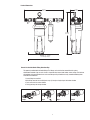
Step 2 Step 3
Step 4
Step 1
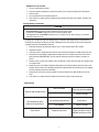
Product Dimensions
18 1/16"
(45.9 cm)
5 7/16"
(13.8 cm)
17 5/16"
(44.0 cm)
Minimum of 3" (7.6 cm)
For Cartridge Change
This product is outfitted with inlet/outlet fittings. The fittings can be attached or removed from the system
without tools. Retention clips are semi-circular in shape with three internal tabs, bottom, center and top. Tab interlaces
withwindowsinthemanifoldheadneareachconnectionport.Clipisexibleandeasilyassembledfollowingthese
instruction and illustrations.
1. Insert fitting into manifold.
2. With fitting inserted into manifold port, snap clip into place beginning at the bottom window
3. Push center tab into center window.
4. Finally push top tab into top window.
How to Use the Inlet/Outlet Fitting Retention Clips
4

Equipment Installation
CAUTION
To reduce the risk associated with property damage due to water leakage:
•Do not use a torch or other high temperature sources near filter system, cartridges, plastic fittings or plastic
plumbing.
•Onplasticttings,neverusepipesealantorpipedope.UsePTFEthreadtapeonly, pipe dope properties may
deteriorate plastic.
•Takecarewhenusingpliersorpipewrenchestotightenplasticttings,asdamagemayoccurifovertight-
ening occurs.
•Do not install near water pipes which will be in path of a drilling tool when selecting the position to mount
the bracket
•Mountlterinsuchapositionastopreventitfrombeingstruckbyotheritemsusedintheareaofinstallation.
•Ensurethatthelocationandfastenerswillsupporttheweightofthesystemwheninstalled.
•Ensurealltubingandttingsaresecureandfreeofleaks.
IMPORTANT NOTES
•Failuretofollowinstructionsmayvoidwarranty.
•Allowaminimumof3”(7.6cm)clearspaceunderltertofacilitatecartridgechange.
•Installwiththeinletandoutletportsaslabeled.Makesurenottoreverseconnections.
•Somelocalcodesmayrequiretheuseofalicensedplumberorcertiedinstallerwhendisruptingapotablewaterline.
The SF1XX manifold may be used with metal or non-metallic piping systems.
CAUTION
To reduce the risk associated with property damage due to water leakage:
•Anynon-metallicttingsusedintheinstallationsmustbeofadequateratingforthelinepressure.
1. Shut off incoming cold water supply.
2. Selecttheinstallationlocation.IMPORTANTNOTE:Allowaminimumof3in(7.6cm)ofspacebelowthecar-
tridge for change-outs.
3. Selectfasteners(notincluded)andtoolsappropriatefortheinstallationlocation(wall,supportstructuremount-
edtowallstuds,concrete,etc.).
CAUTION
To reduce the risk associated with property damage due to water leakage:
•Ensurethatthelocationandfastenerswillsupporttheweightofthesystem(Approx.10.5lbs[4.8kg])
when installed and full of water.
4. Mount the manifold/filter system to a wall using the mounting holes provided on the back plate of the metal
bracket.
•Itisrecommendedtorstdrawalevellineonthemountingsurfaceattheheightofthefasteners.
•Markthelocationofthefastenersusingthebracketasatemplateorbymeasuringthedistancebetween
the mounting holes.
•Installthefastenersandallow1/4”-3/8”(6-10mm)ofeachfastenertoprotrudefromthesurface.
•Installthemanifoldontothefasteners.
•Tightenthefasteners.
5. Installinlet(leftrear)andoutletttings(rightfront).Allconnectionsterminatewitha¾”NPT(male)tting.The
inlet kit includes the fitting and a ball valve. The kit for the right front side outlet includes the fitting, a stainless-
steel tee, a nipple, a check valve and another nipple. Refer to section “How to Use the Inlet/Outlet Fitting
RetentionClips”areonpage4.(PTFEtapeisnotincluded).
6. Remove the sanitary caps from the cartridge, and apply a light coat of water or food-grade lubricant to the o-
rings on each of the cartridges.
7. Align the tabs of the water filter cartridge with the slots in the retaining plate and insert the cartridge into the
manifold.
8. Turnthecartridgetotherightuntilaclickingsoundisheard;theclickingsoundindicatesthecartridgeisprop-
erly engaged.
9. Installthescale-inhibitorcartridgebyengagingthethreadsinthestainlesssteelteeandturningtotheright
(clockwise)untilsnug,regardlessofthenallabelorientation.
5

Equipment Start-up Procedure
1. Turn on incoming water to system.
2. Pressurize system by rotating the inlet ball valve handle 1/4 turn counter-clockwise to the “ON” position.
3. Check for leaks.
4. Use any downstream vent to remove trapped air.
5. Flush system in accordance with the Performance Data Sheet for the water filter cartridge. System is now
ready to use.
Cartridge Change-out Procedure
CAUTION
To reduce the risk associated with property damage due to water leakage:
• Read and follow Use Instructions before installation and use of this system.
•InstallationandUseMUST comply with all state and local plumbing codes.
•ThedisposableltercartridgeMUST be replaced every 12 months or at the rated capacity or if a noticeable
reduction in flow rate occurs.
The water filter cartridge will need to be changed every 6-12 months or when low pressure is indicated on the
manifold’s pressure gauge, whichever occurs first. Depending on local water quality, you may need to change the
cartridges prior to the recommended change-out.
1. Shut off the inlet water by rotating the inlet ball valve 1/4 turn clockwise to the “OFF” position.
2 Depressurize system.
3. Push tab to release cartridge locking mechanism while simultaneously rotating cartridge slightly to the left.
4. Using both hands and holding cartridge from the bottom, rotate the cartridge a quarter turn to the left and
gently pull down. IMPORTANT NOTE: A small amount of water will drain from manifold as cartridge is re-
moved.
5. Remove sanitary cap from new cartridge. Install cartridge with a quarter turn to the right until cartridge comes
to a complete stop.
6. Removethesmallscaleinhibitorcartridgebyrotatingtotheleft(counterclockwise)untilthethreadsaredis-
engaged.Replacewithanewcartridgebyrotatingtotheright(clockwise)untilthethreadsarefullyengaged
and snug, regardless of final label orientation.
7. Slowly turn the inlet ball valve on the manifold 1/4 counter-clockwise to the “ON” position and check for
leaks.
8. Flush system in accordance with the Performance Data Sheet. System is now ready for use.
6
No water flow through system
Inlet valve closed
Filter clogged
Check shut-off valve position
Replace cartridge
Not enough water to the
downstreamapplication(s)
Low incoming water pressure
Filter clogged
Check source
Replace cartridge
Short filter life Temporarily dirty water Change cartridge or install an
additional upstream pre-filter.
Troubleshooting

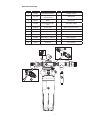
Item Part no. Description Qty* Function
1 6228601 SF1XX Manifold Assembly 1 Assembly, complete
2a 56134-07
HF65 Replacement Cartridge
for SF165 System
1 Water filtration
2b
See Catalog for
Options
Replacement Cartridge
Options
1 Water filtration
3 5582106
HF8-S Replacement Car-
tridge
1 Scale-inhibitor addition
4 85005-49 Pressure gauge 1 Monitor outlet water pressure
5 85-8528 Clip 1 Retain inlet/outlet fittings
6 63597320 O-ring 1 Seal inlet/outlet fittings
7 6225005 Inlet fitting kit –left rear 1 Inlet fitting with ball valve
8 6225007 Outlet fitting kit – right front 1 Outlet to equipment
9 60-235380 3/4”x3/4”ballvalve 1 Inlet water shut-off
10 Inquire Retainer Kit 1 Secure cartridge
Replacement Parts Listing
7
*Per part number, not per system or assembly.
a

3M Purication Inc.warrants SF1XX only to be free from defects in material and workmanship for ve (5) years from the date of purchase.
Thedisposableltercartridgeiswarrantedfromdefectsinmaterialandworkmanshipforaperiodofone(1)year fromthedateofpurchase.
This warranty does not cover failures resulting from abuse, misuse, alterations or damage not caused by 3M Purification Inc. or failure to follow
installation and use instructions. No warranty is given as to the service life of any filter cartridge or membrane as it will vary with local water
conditions and consumption. 3M PURIFICATION INC. MAKES NO OTHER WARRANTIES OR CONDITIONS, EXPRESS OR IMPLIED, INCLUDING,
BUT NOT LIMITED TO, ANY IMPLIED WARRANTY OR CONDITION OF MERCHANTABILITY OR FITNESS FOR A PARTICULAR PURPOSE OR ANY
IMPLIED WARRANTY OR CONDITION ARISING OUT OF A COURSE OF DEALING, CUSTOMER OR USAGE OF TRADE. If the Product fails to satisfy
this Limited Warranty during the warranty period, 3M Purification Inc., at it’s option, will replace the Product or refund your Product purchase price.
This warranty does not cover labor. The remedy stated in this paragraph is Customer’s sole remedy and 3M Purification Inc.’s exclusive
obligation.
This warranty gives you specific legal rights, and you may have other rights which may vary from state to state, or country to country. For any
warrantyquestions,pleasecall866.990.9785ormailyourrequestto:WarrantyClaims,3MPuricationInc.,400ResearchParkway,Meriden,CT
06450.Proofofpurchase(originalsalesreceipt)mustaccompanythewarrantyclaim,alongwithacompletedescriptionoftheProduct,model
number and alleged defect.
Limitation of Liability: 3M Purification Inc. will not be liable for any loss or damage arising from this 3M Purification Inc. product, whether direct,
indirect, special, incidental, or consequential, regardless of the legal theory asserted, including warranty, contract, negligence or strict liability. Some
statesandcountriesdonotallowtheexclusionorlimitationofincidentalorconsequentialdamages,sotheabovelimitationorexclusionmaynot
apply to you.
Limited Warranty
3M Purification Inc.
400 Research Parkway
Meriden, CT 06450
Toll Free: 866.990.9785
Worldwide: 203.237.5541
Fax: 203.238.8897
www.3Mfoodservice.com
www.3Mpurification.com
3M is a trademark of 3M Company.
ScaleGARD is a trademark of 3M Company used under license
© 2012 3M Company. All rights reserved.
INSTR43240912B
Please recycle. Printed in U.S.A.
-
 1
1
-
 2
2
-
 3
3
-
 4
4
-
 5
5
-
 6
6
-
 7
7
-
 8
8


3M High Flow Series Replacement Cartridge Kit, Model CARTPAK SF165, 5613811 User manual
- Category
- Sanitary ware
- Type
- User manual
- This manual is also suitable for
Ask a question and I''ll find the answer in the document
Finding information in a document is now easier with AI
Related papers
-
3M High Flow Series Replacement Cartridge Kit, Model CARTPAK DP295-CL, 5613818 User manual
-
3M ScaleGard™ HP Reverse Osmosis System Operating instructions
-
-
-
-
-
-
-
-
Other documents
-
Aquasana FS-SC-10-R Operating instructions
-
A.O. Smith AO-MF Installation guide
-
aqua-pure 3MFF100 Installation And Operating Instructions Manual
-
aqua-pure AP-RO5500 User manual
-
 AquaPure AQUA-PURE-IL-IM-01 User guide
-
EASTMAN 60246 Installation guide
-
OptiPure QT3MP Installation, Operation & Maintenance Manual
-
GE FQ18MN User manual
-
Everpure EVERPURE Quad User manual
-
Whirlpool WHEMBF5 User manual
