SilverStone RV05 Owner's manual
- Category
- Computer cases
- Type
- Owner's manual
This manual is also suitable for
Page is loading ...
Page is loading ...

The following manual and guides were carefully prepared by the RAVEN engineering team to
help you maximize the potential of your SilverStone product. Please keep this manual for future
reference when upgrading or performing maintenance on your system. A copy of this manual can also
be downloaded from our website at:
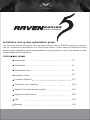
Installation and system optimization guide:
Instroduction
Specification
Disassemble Chart
Installation Guide
Connector Definition
Component Size Limitations
Optimal Thermal Performance Layout
Upgrade And Mainterance
Q&A
Warranty
P.1
P.1
P.2
P.4
P.11
P.14
P.23
P.28
P.34
P.39

1
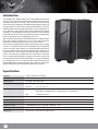
Material
Model
Motherboard
Drive Bay
Cooling System
Expansion Slot
Front I/O Port
Power Supply
Expansion Card
Limitation of CPU cooler
Dimension
Plastic outer shell, steel body
SST-RV05B (black) / SST-RV05B-W (black + window)
SSI-CEB, ATX, Micro-ATX
Exposed Slim slot-loading optical x 1
Internal 3.5" x 2, 2.5” x 2
Bottom 2 x Air Penetrator 180mm fan 600/900/1200rpm, 17/25/34dBA
Downward compatible with 3 x 120mm fan or 2 x 140mm fan
Top 120mm fan slot x 1
7
USB 3.0 x 2 , audio x 1 , MIC x 1
Optional PS2 (ATX)
Compatible with 12.3” long, width restriction – 6.57”
162mm
242 mm (W) x 529 mm (H) x 498 mm (D)
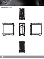
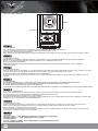
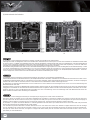
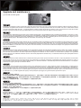
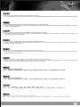
The RAVEN RV05, the fifth edition in the exciting RAVEN enthusiasts
chassis series continues the tradition of breaking and evolving the
standards of desktop PC design. With a bold move that sees the
removal of all 5.25” drive bays, the RAVEN team engineers again saw
the opportunity to re-utilize the 90 degree rotated design. Previous
RAVEN models with 90 degree layout often had to compromise on
space efficiency due to fixed length of the motherboard in rotated
orientation. The elimination of 5.25” bays solves this issue naturally
and enables RV05 to be even more balanced in terms of design than
if the same were done to a traditionally-layout case.
With most of the wasted space eliminated from RV05, engineers were
thus able to better optimize the case for the most important
performance-affecting components such as CPU and GPUs.
The result is an expertly-engineered ATX chassis that is just as capable
in terms of compute power and heat dissipation as the first RAVEN
chassis, the RV01, but in half the size. Equipped with latest revision
Air Penetrator AP181 fans that include three speed switches and
modern touches such as externally removable filters and tool-less
panels, the RV05 has everything that PC enthusiasts could wish
for in a compact, high performance computer case that is not only cool
and quiet, but also easy to build and maintain. For those not wanting
to constantly step up in case size to obtain top-level performance,
the RAVEN RV05 is the perfect solution and it may also represent a
glimpse into the future of mainstream enthusiasts PC design.
Introduction
Specification

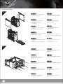
MANUAL
FF143-FILTER
BUNCH WIRE TIES
ZIPPER BAG
STANDOFF-SOCKET-WRENCH
STANDOFF-6-32 X6.5H-6-32
SCW-6-32
SCW-M3
SCW-M2
ZIPPER BAG
SCREW - PAN - 4 X 4.8H - 6 - 32 X 3.4 - NI
USER INSTALLATION GUIDE
FAN FILTER FOR REAR 120MM PSU VENT
CABLE MANAGEMENT
CONTAINS SCREWS
STANDOFF SCREWS
MOTHERBOARD STABDOFF
SECURE MOTHERBOARD AND PSU
SECURE 2.5” HDD
SECURE SLIM SLOT-LOADING OPTICAL DRIVE
CONTAINS PARTS
SECURE 3.5* HDD
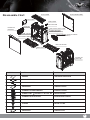
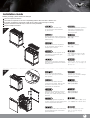
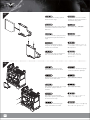
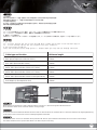
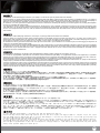
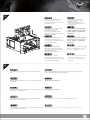
PICTURE ITEM PURPOSE
RIGHT-SIDE-PANELTOP COVER
USB COVER
USB 3.0 X2 + MIC + SPK
POWER BUTTON
12025 FAN (OPTION)
SLOT-LOADING OPTICAL DRIVE
(SOLD SEPARATELY)
BOTTOM-FILTER
18032 FAN X2
LEFT-SIDE-PANEL
ATX MB (OPTION)
PSU
(OPTION)
PUS FILTER
3.5”HDD X2
(OPTION)
2.5”HDD X2
(OPTION)
RESET BUTTON
2
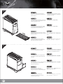
Disassemble Chart
Page is loading ...

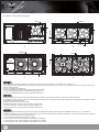
01
02
Ziehen Sie die obere Abdeckung
des Gehäuses in die dargestellte
Pfeilrichtung.
Retirez le couvercle supérieur
en le poussant dans le sens
indiqué par la flèche.
Saque la cubierta superior de la
carcasa en la dirección que
indica la flecha
Sollevare il coperchio superiore
del case nella direzione indicata
dalla freccia
Pull top cover off the case
in the direction as illustrated
by the arrow
Снимите верхнюю крышку с
корпуса в направлении,
указанном стрелкой на
иллюстрации.
그림과 같이 화살표 방향으로
케이스에서 상단 커버를 당겨
분리합니다.
請按鍵頭方向用力,
取出上蓋
请按键头方向用力,
取出上盖
Drücken und halten Sie den
verborgenen Hebel. Ziehen Sie
ihn dann nach oben, um die
Seitenteile zu entfernen.
Appuyez et maintenez enfoncé
le levier caché, puis tirez vers
le haut pour retirer les panneaux
latéraux
Presione y aguante la palanca
oculta, luego tire hacia arriba para
retirar los paneles laterales
Tenere premuta la leva nascosta,
quindi sollevare per rimuovere i
pannelli laterali
Press and hold the hidden
lever, then pull up to remove
side panels
Нажав на скрытые
фиксаторы, снимите вверх
боковые панели.
숨겨진 레버를 누른 채로
위로 당겨 측면 패널을
분리합니다.
請按壓內部暗釦,
拆除左右兩側板
请按压内部暗扣,
拆除左右两侧板
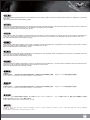
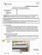
have all components collected
check that all components do not have compatibility problems with each other or with the case
if possible, assemble the components outside the case first to make sure they are working
keep the motherboard manual ready for reference during installation
prepare a Philips screwdriver.
1
2
3
4
5
Before you begin, please make sure that you
4
Installation Guide

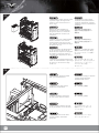
03
04
Bauen Sie das Netzteil ins
Gehäuse ein. Ist das Netzteil
länger als 160 mm, entfernen
Sie den Rahmen für das 3,5”
Laufwerk.
Installez la source d’alimentation
dans le châssis. Si la source
d’alimentation est plus longue
que 160mm, alors retirez la cage
de disque de 3,5"
Instale la fuente de alimentación
en la carcasa. Si la fuente de
alimentación supera una longitud
de 160mm, entonces retire la
carcasa para dispositivos de 3,5”
Installazione dell’alimentatore nel
case. Se l'alimentatore è più lungo
di 160 mm, rimuovere il cage
unità 3.5”
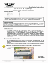
Install power supply into the case.
If power supply is longer than
160mm, then remove the 3.5”
drive cage
Установите в корпус блок
питания. Если длина блока
питания превышает 160 мм,
снимите отсек 3,5-дюймового
привода.
전원 공급장치를 케이스에
설치합니다. 전원 공급장치가
160mm보다 긴 경우 3.5”
드라이브 케이지를
제거합니다.
安裝電源,如果電源長度
超過160mm的話請拆除3.5”
硬碟架
安装电源,如果电源长度
超过160mm的话请拆除3.5”
硬盘架
Installieren Sie das hintere
I/O-Blech im Gehäuse.
Installez la plaque arrière de
la carte mère dans le boîtier.
Instale la placa trasera de E/S
de la placa base en la carcasa.
Installare la placca I/O della
scheda madre nella sede
preposta.
Insert the I/O shield included
with your motherboard
Установите в корпус заднюю
панель ввода-вывода
материнской платы.
메인보드 후방 I/O 판을
케이스에 장착합니다.
將I/O彈片裝上機殼
将I/O弹片装上机壳
5

05
06
Stecken Sie die Abstandshalter
wie für Ihr Motherboard
erforderlich in die entsprechenden
Befestigungsbohrungen.
Installieren Sie dann das
Motherboard.
Insérez les entretoises comme
requis par votre carte mère dans
les trous de montage
correspondant, puis installez
la carte mère
Inserte los soportes según sea
necesario para su placa base
en los agujeros de montaje
correspondientes, luego instale
la placa base
Inserire nei corrispondenti fori di
fissaggio i distanziatori, come
richiesto dalla scheda madre,
quindi installare la scheda madre
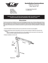
Insert standoffs as required
by your motherboard in
corresponding mounting holes,
then install motherboard
При необходимости установите
опорные стойки для системной
платы в соответствующие
крепежные отверстия, затем
установите системную плату.
메인보드에서 필요한 경우
해당 장착 구멍에 스탠드오프를
삽입한 후 메인보드를
설치합니다.
請依需求安裝主機板螺柱,
安裝主機板
请依需求安装主板螺柱,
安装主板
Demontieren Sie dann den
Rahmen für das optische
Laufwerk im Slim-Format.
Retirez la cage de lecteur
optique mince
Retire la carcasa para dispositivo
óptico delgado
Rimuovere il cage unità ottica slim
Remove slim optical drive cage
Снимите тонкий отсек
оптического привода.
슬림형 광 드라이브 케이지를
제거합니다.
請移除光碟機架
请移除光驱架
6

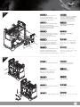
07
08
Befestigen Sie dann das optische
Laufwerk im Slim-Format in dem
Rahmen.
Installez le lecteur optique mince
à chargement par fente dans la
cage
Instale el dispositivo óptico
delgado de carga mediante
ranura en la carcasa
Installare nel cage l’unità ottica
slim con caricamento a slot
Install slim slot-loading optical
drive into the cage
Установите в отсек тонкий
привод оптических дисков с
щелевой загрузкой.
슬림형 슬롯 로딩 광
드라이브를 케이지에
설치합니다.
將光碟機安裝上光碟機架
将光驱安装上光驱架
Montieren Sie dann den Rahmen
wieder im PC-Gehäuse.
Réinstallez l'ensemble de la cage
de lecteur optique dans le
châssis
Reinstale la carcasa para
dispositivo óptico ya montada
de nuevo en la caja
Reinstallare l’assemblaggio
cage unità ottica nel case
Reinstall optical drive cage
assembly back into the case
Установите на место в корпус
отсек оптического привода.
광 드라이브 케이지 어셈블리를
케이스에 도로 설치합니다.
請將光碟機架裝回機殼
请将光驱架装回机壳
7

09
10
Schieben Sie die 3,5” Laufwerke
in den Laufwerkrahmen und
sichern Sie jedes Laufwerk mit
einer Rändelschraube.
Insérez un disque de 3,5"
dans la cage de disque si
nécessaire, attachez chaque
disque avec une vis de serrage
Instale los dispositivos de 3,5” en
la carcasa para dispositivos, si es
necesario, asegure cada
dispositivo con un tornillo de
pulgar
Se necessario, inserire le unità
3,5” nel cage unità, fissando
ciascuna unità con una vite ad
alette
Insert 3.5” drives into the drive
cage, if needed, secure each
drive with a thumb screw
Установите 3,5-дюймовые
приводы в отсек для дисков,
при необходимости закрепите
каждый привод винтом с
накатанной головкой.
필요한 경우 3.5” 드라이브를
드라이브 케이지에 설치하고
납작머리 나사로 각 드라이브를
고정합니다.
將3.5”硬碟推入硬碟架,
必要的話鎖上一顆手扭螺絲
将3.5”硬盘推入硬盘架,
必要的话锁上一颗手扭螺丝
Montieren Sie die 2,5” Laufwerke
hinter der Motherboard-Aufnahme
und sichern Sie sie mit Schrauben.
Installez des disques de 2,5"
derrière le plateau de la carte
mère et attachez avec des vis
Instale los dispositivos de 2,5”
tras la bandeja de la placa base
y fíjelos con tornillos
Installare le unità 2,5” dietro
il cassetto della scheda madre
e fissarle con viti
Install 2.5” drives behind the
motherboard tray and secure
with screws
За лотком системной платы
установите 2,5-дюймовые
приводы и закрепите их
винтами.
메인보드 트래이 뒤에 2.5”
드라이브를 설치하고 나사로
고정합니다.
將2.5”硬碟裝上主機板背面,
並鎖上螺絲
将2.5”硬盘装上主板背面,
并锁上螺丝
8

11
12
Schließen Sie alle Kabel an.
Branchez tous les câbles
et les fils
Conecte todos los cables
Collegare tutti i cavi ed i fili
Connect all cables and wires
Подключите все кабели
и провода.
모든 케이블과 전선을
연결합니다.
將連接所有線材
将连接所有线材
Bringen Sie die Seitenteile
wieder an.
Réinstallez les panneaux
latéraux sur le châssis
Reinstale los paneles laterales
de nuevo en la carcasa
Reinstallare sul case i pannelli
laterali
Reinstall side panels back
onto the case
Установите на место
боковые панели корпуса.
측면 패널을 케이스에 도로
설치합니다.
裝回左右側板
装回左右侧板
9
S
chlie
ß
en
S
i
e
Br
a
n
c
h
e
z t
ou
e
t l
es
f
i
ls
C
onecte tod
o
C
olle
g
are tut
t
Connect
all
c

10
13
Bauen Sie die obere Abdeckung wieder ein.
Die Installation ist damit beendet.
Réinstallez le panneau supérieur pour terminer
l'installation
Reinstale el panel superior para completar
la instalación
Reinstallare il pannello superiore per completare
l'installazione
Reinstall the top panel to complete installation
И, наконец, установите на место верхнюю панель.
상단 패널을 도로 설치하여 설치를 완료합니다.
裝回上蓋完成組裝
装回上盖完成组装

11
Connector definition
(1) Fort panel connector installation
Power switch and reset switch installation guide:
Please refer to the motherboard manuals for the motherboard’s “Front Panel Connector” or “System Panel Connector” pin definition.
Power switch and reset switch have no polarity, so they can be connected in any orientation.
Ein-/Ausschalter und Rücksetztaste (Reset) installieren:
Bitte suchen Sie in der Motherboard-Dokumentation nach der Pinbelegung der Anschlüsse des Frontbedienfeldes („Front Panel Connectors“
oder „System Panel Connectors“). Ein-/Austaste und Rücksetztaste benötigen keine bestimmte Polarität, können daher beliebig (ohne auf +
und - zu achten) angeschlossen werden.
Guide d'installation des interrupteurs d'allumage et de réinitialisation :
Veuillez-vous référer au manuel de votre carte mère pour la description des broches "des connecteurs du panneau frontal" et des broches "des
connecteurs du panneau système". Les interrupteurs d'allumage et de réinitialisation ne possède pas de polarité, donc ils peuvent être branché
dans les deux sens.
Guía de instalación de los interruptores de encendido y reseteo:
Por favor, consulte en los manuales de la placa base la configuración de pines del “Conector de panel frontal” ó “Conector de panel de sistema”
de su placa base. Los interruptores de encendido y reseteo no tienen polaridad, luego se pueden conectar con cualquier orientación.
Guida all’installazione dei connettori Power Switch e Reset Switch:
Fare riferimento al manuale della scheda madre nella sezione “Connettori del pannello frontale” o “Connettori del pannello di sistema”.
Power switch e reset switch non hanno polarità, posso essere pertanto connessi con qualsiasi orientamento.
Инструкция по подключению выключателя питания и кнопки перезагрузки (reset):
Описание контактов разъемов приведены в разделах “Разъемы передней панели” или “Разъемы системной панели” руководства
пользователя материнской платы. Выключатель питания и кнопка перезагрузки не имеют полярности, поэтому их можно подключать
в
любой ориентации.
파워 스위치 및 리셋 스위치 설치 가이드
메인보드 매뉴얼의 전면패널 커넥터 혹은 시스템패널 커넥터 핀을 참조하기 바랍니다. 파워 스위치와 리셋 스위치는 극성이 없어
어떤 방향으로 설치해도 무방합니다.
電源スイッチおよびリセットスイッチのインストールガイド:
マザーボードの「フロントパネルコネクタ」または「システムパネルコネクタ」のピン配列についてはマザーボードマニュアルを参照
してください。電源スイッチとリセットスイッチに極性はないので、いずれの方向でも接続できま。
Power Switch 與Reset Switch安裝說明:
請參考主機說明書的Front Panel Connectors安裝Pin Define,將Connector插上;Power Switch 與Reset Switch並無正負極性之分,
反插正插都不影響功能性。
Power Switch 与Reset Switch安装说明:
请参考主机说明书的Front Panel Connectors 安装Pin Define,将Connector插上;Power Switch与Reset Switch并无正负极性之分,
反插正插都不影响功能性。

12
LED connector installation guide:
Please refer to the motherboard manuals for the motherboard’s “Front Panel Connector” or “System Panel Connector” pin definition. White colored
wires are negative while other colored wires are positive. Power LED connector is made to be individual pins by design to accommodate different
motherboard specifications.
:
Bitte suchen Sie in der Motherboard-Dokumentation nach der Pinbelegung der Anschlüsse des Frontbedienfeldes („Front Panel Connectors“ oder „
System Panel Connectors“). Die weißen/ schwarz Adern sind negativ (-), die farbigen Adern positiv (+).Die Kabel für die Betriebsanzeige-LED sind
zur Kompatibilität mit unterschiedlichsten Motherboards einzeln, nicht als kompletter Stecker ausgeführt. Achten Sie hier bitte auf die richtige Polarität,
lesen Sie in der Dokumentation Ihres Motherboards nach.
Veuillez-vous référer au manuel de votre carte mère pour la description des broches "des connecteurs du panneau frontal" et des broches "des
connecteurs du panneau système". Les câbles colorés en blanc/noir sont négatifs alors que ceux d'une autre couleur sont positifs. Les câbles de
la LED Power sont séparés afin d'être compatible avec différentes cartes mères, donc vérifiez bien qu'ils sont branchés avec la bonne polarité en
vous référant au manuel de votre carte mère
Por favor, consulte en los manuales de la placa base la configuración de pines del “Conector de panel frontal” ó “Conector de panel de sistema”
de su placa base. Los cables de color blanco/negro son negativos mientras que los de color son positivos. Los cables LED de potencia tienen
pines separados para compatibilidad con diferentes definiciones de pines de la placa base luego por favor, asegúrese de que están conectados
en la polaridad correcta consultando el manual de su placa base.
Fare riferimento al manuale della scheda madre nella sezione “Connettori del pannello frontale” o “Connettori del pannello di sistema”. I cavi di
colore bianco/nero sono il polo negativo, mentre quelli di colore diverso il positivo.
Описание контактов разъемов приведены в разделах “Разъемы передней панели” или “Разъемы системной панели” руководства
пользователя материнской платы. Белые/черный провода - отрицательной полярности, цветные провода - положительной полярности.
Провода светодиодного индикатора питания имеют отдельные контакты для совместимости
с различными типами контактов материнских
плат, поэтому обратитесь к руководству пользователя материнской платы и убедитесь, что полярность соблюдена.
請參考主機說明書的Front Panel Connectors安裝Pin Define,將Connector插上; 白/黑色線的部分為負極,彩色線的部分是正極。Power LED為了適
應各主機板的不同, 特別設計為散Pin樣式,請安心使用。
请参考说明书的Front Panel Connectors安装Pin Define,将Connector插上;白/黑色线的部份为负极,彩色线的部份为正极。Power LED为了适应主机
板的不同, 特别设计为散Pin样式,请安心使用。
マザーボードの「フロントパネルコネクタ」または「システムパネルコネクタ」ピン配列についてはマザーボードマニュアルを参照してください。
白/黑色のリード線はマイナスで、色の着いたリード線がプラスです。電源LEDリード線は種々のマザーボードピン定義と互換性を持たせるため分離
されたピンとなっているので、ご使用のマザーボードマニュアルを参照して、適切な極性に接続されるようお確かめください。
메인보드 매뉴얼의 전면패널 커넥터 혹은 시스템패널 커넥터 핀을 참조하기 바랍니다. 하얀/검은선의 경우 음극이며, 다른 색의 경우
양극입니다. 파워 LED 선은 분리되어 다양한 메인보드에서 동작할 수 있도록 되어 있습니다. 그러므로 메인보드 매뉴얼을 참조하여 올바를
극성을 주의해 선택하시기 바랍니다.
Page is loading ...

14
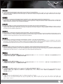
Height limitation for CPU cooler is 162mm with 13mm clearance over the motherboard’s top edge.
Höhenbeschränkung für CPU-Kühler 162 mm mit einem Freiraum von 13 mm oberhalb der Motherboard-Oberkante.
La limitación de altura para disipadores de CPU es de 162mm con un espacio libre de 13mm sobre el borde superior de la placa base.
La limitazione dell’altezza del dissipatore di calore CPU è di 162 millimetri con uno spazio libero di 13 mm sopra il bordo superiore della scheda madre.
Ограничение по высоте для системы охлаждения процессора составляет 162 мм с 13-мм зазором над верхним краем системной платы.
Cooler限高是162mm,Cooler外源允許超出主機板上邊界13mm
Cooler限高是162mm,Cooler外源允许超出主板上边界13mm
CPUクーラーの高さ限度は、マザーボード上側の余裕13mmを取って、162mmです。
CPU 쿨러의 높이 제한은 162mm로서 메인보드 상단 가장자리 위로의 허용 오차가 13mm입니다.
La limitation de hauteur des refroidisseurs de processeurs est 162mm avec un espace de 13mm au-dessus du bord supérieur de la carte mère.
Component size limitations
The RAVEN RV05 was designed to accommodate oversized components, but we still recommend referring
to the following dimension guidelines
(1) CPU Cooler limitation
162mm
9mm 13mm

15
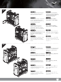
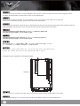
(2) Power supply limitation
343.8mm
160mm
A: Length limitation
If no 3.5” drives are installed, there is no limitation on power supply size with the drive cage removed
If the 3.5” drive cage is in use, the recommended depth of the power supply is 160mm
B: Power supply cable length recommendation
Below is the recommended cable length for retail ATX motherboards. If the cables are not long enough, please purchase extension cables.
A: Längenbeschränkung
Werden keine 3,5” Laufwerke installiert und wird der Laufwerkrahmen entfernt, unterliegt das Netzteil keiner Größenbeschränkung.
Wir der 3,5” Laufwerkrahmen verwendet, liegt die empfohlene Tiefe des Netzteils beim 160 mm.
B: Längenempfehlung Netzteilkabel
Nachfolgend finden Sie die empfohlenen Kabellängen für handelsübliche ATX-Motherboards. Sind die Kabel zu kurz, kaufen Sie
Verlängerungskabel.
A: Limitación de altura
Si no se instalan dispositivos de 3,5”, no existirá limitación en el tamaño de la fuente de alimentación con la carcasa para dispositivos retirada
Si se usa la carcasa para dispositivos de 3,5”, la profundidad recomendada de la fuente de alimentación será de 160mm
B: Recomendación de la longitud del cable de la fuente de alimentación
A continuación se encuentra la longitud de cable recomendada para placas base ATX. Si los cables no son lo bastante largos, por favor compre cables de extensión.
A: Ограничение по длине
Если 3,5-дюймовые приводы не устанавливаются, ограничений на размер блока питания при снятом отсеке для приводов нет
Если отсек 3,5-дюймовых приводов используется, рекомендуемая глубина блока питания составляет 160 мм
B: Рекомендации по длине кабелей блока питания
Ниже приведены рекомендации по длине кабелей для самостоятельно приобретаемых системных плат ATX. Если длина кабелей
недостаточна, приобретите удлинительные кабели.
A: Limitazione della lunghezza
Se non sono installate unità 3,5”, quando è rimosso il cage unità, non c’è alcuna limitazione per le dimensioni dell’alimentatore
Se il cage unità 3,5” è in uso, la profondità raccomandata per l'alimentatore è di 160 mm
B: Raccomandazioni sulla lunghezza del cavo d’alimentazione
Di seguito sono elencate le lunghezze raccomandate dei cavi d’alimentazione per le schede madre ATX vendute al dettaglio. Acquistare delle
prolunghe qualora i cavi non fossero sufficientemente lunghi.
A:長度限制
如果下方沒有安裝3.5”硬碟,電源就幾乎沒有長度限制,您可以使用任何超大瓦數的電源
如果電源前方有安裝3.5” 硬碟,我們建議您使用160mm以內的電源
B:電源線材建議長度:
以下是以一般市售ATX主機板抓出來的各線材建議長度列表,請先確認電源線長度是否足夠
如果不夠請選購所需要的延長線
A : Limitation de longueur
Si aucun disque de 3,5" n'a été installé, il n'y a aucune limitation pour la taille de la source d'alimentation lorsque la cage de disque a été retiré
Si la cage de disque de 3,5" est utilisée, la profondeur recommandée pour la source d'alimentation est 160mm
B : Recommandations pour la longueur du câble de la source d’alimentation
Ci-dessous est la longueur de câble recommandée pour les cartes mères ATX. Si les câbles ne sont pas assez long, veuillez acheter des
rallonges.

16
A:长度限制
如果下方没有安装3.5”硬盘,电源就几乎没有长度限制,您可以使用任何超大瓦数的电源
如果电源前方有安装3.5” 硬盘,我们建议您使用160mm以内的电源
B:电源线材建议长度:
以下是以一般市售ATX主板抓出来的各线材建议长度列表,请先确认电源线长度是否足够
如果不够请选购所需要的延长线
A: 長さ制限
3.5”ドライブが装着されていない場合、ドライブケージなしでは電源のサイズに制限はありません。
3.5”ドライブケージが使用される場合、推奨される電源奥行きは160mmです。
B: 電源ケーブル推奨長さ
下図はリテールATXマザーボード用のケーブル推奨長さです。ケーブル長が不十分の場合は、延長ケーブルをご購入ください。
A: 길이 제한
3.5” 드라이브가 설치되지 않은 경우 드라이브 케이지를 제거한 상태에서 전원 공급장치 크기에 대한 제한이 없습니다.
3.5” 드라이브 케이지를 사용 중인 경우 전원 공급장치의 권장 깊이는 160mm입니다.
B: 권장 전원 공급장치 케이블 길이
다음은 소매 ATX 메인보드용 권장 케이블 길이입니다. 케이블이 충분히 길지 않을 경웅 연장 케이블을 구매하십시오.
Cable type and location
EPS 8pin/ATX4pin (from left side of PSU)
ATX 24Pin (from left side of PSU)
SATA 15Pin (from left side of PSU to 3.5” drive)
SATA 15Pin (from left side of PSU to 2.5” drive)
SATA 15Pin (from left side of PSU to slim optical drive)
PCIE 8/6pin (to first expansion slot)
Minimum length
550mm
300mm
100mm
300mm
350mm
450mm
When using a non-modular PSU with a depth of 140mm, route the CPU 8/4 Pin through the indicated hole first.
PP07 extension cables can be used if the cable is not long enough.
Bei Einsatz eines nicht-modularen Netzteils mit einer Tiefe von 140 mm führen Sie zunächst den CPU-Anschluss 8/4 durch die angezeigte Bohrung.
Ist das Kabel zu kurz, können Sie ein PP07-Verlängerungskabel verwenden.
Quand vous utilisez un PSU non-modulaire d'une profondeur de 140 mm, placez d'abord la broche 8/4 du CPU à travers le trou indiqué.
Des câbles d'extension PP07 peuvent être utilisés si le câble n'est pas assez long.
mm320.241Distance
mm320.241Distance

17
Cuando se usa una FA no modular con una profundidad de 140mm, primero enrute los 8/4 pines de la CPU a través del agujero indicado.
Los cables de extensión PP07 se pueden usar si el cable no es lo bastante largo.
Quando si usa una PSU non modulare con una profondità di 140 mm, prima infilare nel foro indicato i pin 8/4 della CPU.
Se il cavo non è sufficientemente lungo, possono essere usati cavi di prolunga PP07.
При использовании немодульного блока питания с глубиной 140 мм сначала пропустите разъем процессора 8/4 через показанное отверстие.
Если длина кабеля окажется недостаточной, в корпусе PP07 можно использовать удлинительные кабели.
如果是使用低階非模組化的電源,電源深度為140mm CPU 8/4 Pin請優先由主機板前方穿過
走最短距離,如果不幸長度還是不足,你可以購買PP07延長線
如果是使用低阶非模块化的电源,电源深度为140mm CPU 8/4 Pin请优先由主板前方穿过
走最短距离,如果不幸长度还是不足,你可以购买PP07延长线
奥行き140mmの非モジュール式PSUを使用する場合、CPU 8/4ピンを表示された孔に通してください。
ケーブル長が不足している場合は、PP07延長ケーブルが利用できます。
깊이가 140mm인 비모듈식 PSU를 사용하는 경우, 먼저 CPU 8/4 핀을 표시된 구멍을 통과시키십시오.
케이블의 길이가 충분히 길지 않을 경우 확장 케이블 PP07을 사용할 수 있습니다.
(3) Graphics card / expansion card length limitation
314.2mm
RV05 can support 12.3” (314.2mm) long cards, which covers all retail consumer graphics cards available on the market.
RV05 unterstützt Karten bis 12,3” (314.2mm). Dies deckt alle auf dem Markt verfügbare Consumer-Grafikkarten ab.
Page is loading ...

19
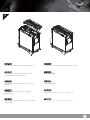
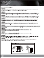
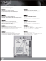
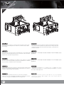
(5) Motherboard size limitation
A. Illustration: ASUS Rampage III Extreme for example is wider than standard ATX motherboards
Although RV05 was not designed for reference Extended-ATX motherboard, the internal space can still allow installation for motherboards with width
of up to 11 inches. In addition, the motherboard tray has mounting standoffs for supporting SSI-CEB dual CPU motherboards. Enthusiast motherboards
such as ASUS’s Rampage III Extreme and EVGA’s X58 Classified 4-Way SLI are 10.6 and 10.375 inches wide respectively. These are wider than
standard ATX motherboard specification of 9.6 inches, but will fit inside RV05 without any problems.
B. Illustration: New generation of SSI-CEB server or workstation motherboards no longer require CPU cooler mounting holes on the motherboard tray. Coolers
can now be installed directly on the motherboard. As a result, we eliminated support for SSI-CEB CPU cooler mounting holes and instead increased
the large gap on the motherboard tray to support CPU cooler back plates swapping with modern LGA 1156/1155/1150 motherboards. The RV05
chassis’ support for new and future SSI-CEB motherboards should be unaffected by this change.
AB
A. Abbildung: Die ASUS Rampage II Extreme beispielsweise ist breiter als ein Standard-ATX-Motherboards.
Obwohl das RV05 keine echten Extended ATX- (SSI-EEB) Motherboards unterstützt, unterstützt es ATX-Modelle mit einer Breite bis 11-Zoll. Löcher
für Motherboard-Abstandhalter sind zur Unterstützung von SSI-CEB verfügbar, sodass High-End-Enthusiasten ATX-Platinen, wie ASUS Rampage III
Extreme oder EVGA X58 SLI Classified, die bis zu 10,6-Zoll breit sind, komfortabel im RV05 unterbringen können.
B. Abbildung: Hochmoderne Motherboards von SSI-CEB-Servern und -Arbeitsrechnern benötigen keine Löcher zur CPU-Kühlermontage am
Motherboard-Einschub mehr.
Die Kühler können nun direkt am Motherboard installiert werden. Dadurch haben wir die Unterstützung der Löcher zur SSI-CEB-CPU-Kühlermontage
aufgegeben und stattdessen den Abstand am Motherboard-Einschub vergrößert; dadurch werden CPU-Kühlerrückplatten unterstützt, die mit einer
größeren Anzahl an LGA 115X-Motherboards kompatibel sind. Die Unterstützung neuer und zukünftiger SSI-CEB-Motherboards durch das
RV05-Gehäuse wird durch diese Änderung nicht beeinflusst.
A. Illustration : ASUS Rampage III Extreme par exemple est plus large que les cartes mères standard ATX
Bien que le RV05 ne supporte pas les cartes mères Extended ATX (SSI-EEB), il supporte les modèles ATX jusqu'à 11 pouces de large. Des trous
pour les espaceurs de carte mère sont inclus pour supporter SSI-CEB pour que les cartes ATX de haut de gamme tels que ASUS Rampage III
Extreme ou EVGA X58 SLI Classified, qui ont une largeur de jusqu'à 10,6", puissent rentrer facilement à l'intérieur du RV05.
B. Illustration : Les portes-carte mère destinés à la nouvelle génération de cartes mères pour station de travail ou serveur SSI-CEB n'ont plus besoin
de trous de montage pour le refroidisseur de l'unité centrale.
Les refroidisseurs peuvent désormais s'installer directement sur la carte mère. Nous avons ainsi éliminé le support destiné aux trous de montage
pour le refroidisseur de l'unité centrale SSI-CEB et l'espace sur le porte-carte mère permettant de permuter les plaques arrière du refroidisseur,
avec plus de cartes mères LGA 115X, est agrandi. Le support du châssis RV05 pour les nouvelles cartes mères SSI-CEB et celles à venir, ne sera
pas affecté par cette modification.
Page is loading ...

21
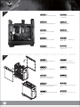
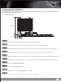
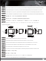
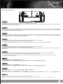
(6) Liquid cooling radiator limitations
The bottom panel of RV05 supports fan mountings of radiator with sizes of 180mm x 2, 140mm x 2, or 120mm x 3.
Since radiators have different designs with how much they protrude from the frame of fans, we recommend double check their dimensions
with the following guide:
A: Area surrounding top 120mm fan
B: Area surrounding the bottom if mounted with three 120mm fans
C: Area surrounding the bottom if mounted with two 140mm fans
D: Area surrounding the bottom if mounted with two 180mm fans
Die Bodenplatte des RV05 unterstützt die Befestigung von Kühlern in den Größen 180 mm 2x, 140 mm 2x oder 120 mm 3x.
Da Radiatoren unterschiedlich aufgebaut sind und unterschiedlich weit vom Rahmen des Lüfters herausragen, empfehlen wir ihre Maße anhand
der folgenden Hinweise zu prüfen:
A: Bereich um den oberen 120 mm Lüfter
B: Bereich am Boden, wenn drei 120 mm Lüfter installiert sind
C. Bereich am Boden, wenn zwei 140 mm Lüfter installiert sind
D: Bereich am Boden, wenn zwei 180 mm Lüfter installiert sind
Le panneau inférieure du RV05 supporte le montage de ventilateurs de radiateur avec des tailles de 180mm x 140mm x 2, 2, ou 120mm x 3.
Puisque les radiateurs ont des designs différents tels que comment ils dépassent du cadre des ventilateurs, nous vous recommandons de vérifier
à nouveau leurs dimensions avec le guide suivant :
A : Zone autour du ventilateur supérieur de 120mm
B : Zone autour du bas si trois ventilateurs de 120 mm sont installés
C : Zone autour du bas si deux ventilateurs de 140 mm sont installés
D : Zone autour du bas si deux ventilateurs de 180mm sont installés
2.2mm
13.1mm 3.6mm
AB
C
D
22.8mm
101mm
27.8mm
32.1mm
33mm
31.8mm
37.5mm
3mm
7.5mm
32.8mm
34.6mm
19.8mm18.8mm
Page is loading ...

23
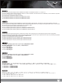
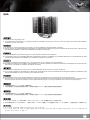
If you are installing a tower-style CPU cooler, we recommend that the CPU fan blows upward to work with RV05’s overall airflow.
Falls Sie einen turmartigen CPU-Kühler installieren, empfehlen wir, den CPU-Lüfter die Luft nach oben blasen zu lassen, damit er mit der
gesamten Luftbewegung im RV05 zusammenarbeitet.
Si está instalando un refrigerador para CPU estilo torre, le recomendamos que el ventilador de la CPU empuje el aire hacia arriba para ayudar
al flujo de aire general de la RV05.
Se scegliete un dissipatore a torre, assicuratevi che il flusso d’aria della ventola sia disposto verso l’alto, per seguire in modo naturale il flusso
interno di RV05.
Если вы устанавливаете башенный кулер ЦП, то мы рекомендуем установить его таким образом, чтобы воздушный поток вентилятора
ЦП был направлен вверх и совпадал с общим направлением воздушного потока внутри корпуса RV05.
如果您使用塔型散熱器,我們建議您將散熱器安裝方向為風扇往上吹的方式,以順著RV05的風流
Si vous installez un dissipateur de processeur de type "tour", nous vous recommandons que le ventilateur du dissipateur souffle vers le haut
pour fonctionner dans le même sens que le flux d’air généré par le RV05 lui-même.
Optimal Thermal Performance Layout
(1) CPU Cooler
如果您使用塔型散热器,我们建议您将散热器安装方向为风扇往上吹的方式,以顺着RV05的风流
タワースタイルCPUクーラーを取り付ける場合、RV05の全体の気流に合わせた動作のため、CPUのエアーが上方に送られる設置方向をお勧めし
ます。
만약 타워 스타일의 CPU 쿨러를 설치하려 한다면, CPU 팬이 상부 쪽을 불도록 해야, RV05의 전체적인 공기흐름에 맞춰 원활하게
동작합니다.
d
th
tth
CP
Uf
bl
dt
k
y

24
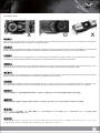
When choosing a graphics card, we recommend models that have fan blowing exhaust air to the rear slot, this will ensure smooth and
efficient airflow within the RV05 for maximum cooling performance.
Bei der Auswahl von Grafikkarten empfehlen wir Modelle, die warme Luft über eine Öffnung im hinteren Teil des Steckplatzes in die Außenwelt
ableiten; dies gewährleistet eine ungestörte und wirksame Luftzirkulation innerhalb des RV05 und sorgt für eine optimale Kühlung.
Cuando escoja una tarjeta gráfica, le recomendamos modelos que tengan la salido de aire del ventilador hacia el zócalo trasero, esto le
asegurará un flujo de aire suave y eficiente dentro de la RV05 para así conseguir una capacidad de refrigeración máxima.
Quando scegliete una scheda grafica, vi raccomandiamo di optare per un modello che espella l’aria al di fuori del case, questo assicurerà un
più efficiente flusso d’aria e massimizzerà le prestazioni di raffreddamento interno di RV05.
Мы рекомендуем выбирать такие модели графических карт, у которых вентилятор гонит отработанный воздух к заднему слоту.
Это обеспечивает беспрепятственную и эффективную циркуляцию воздуха в корпусе RV05 и максимальную защиту от перегрева.
如果您安裝高階顯示卡,我們建議您選購風向為朝向Slot端的方式,這樣安裝上RV05時,風扇才會朝後吹,順著RV05的氣流配置
Lorsque vous choisirez une carte graphique, nous recommandons les modèles qui ont des ventilateurs qui soufflent par l'équerre arrière,
ceci assurera un flux d'air régulier et efficace dans le RV05 pour des performances de refroidissement maximales.
如果您安装高阶显示适配器,我们建议您选购风向为朝向Slot端的方式,这样安装上RV05时,风扇才会朝后吹,顺着RV05的气流配置
グラフィックカードを選ぶ際、ファン送風が後部スロット方向に排気を行うモデルを推奨します。これはRV05の中にスムーズで効率的な気流
を生じ、最大の冷却性能を実現します。
그래픽 카드를 선택할때, 슬롯 후면으로 팬의 바람 방향이 슬롯 후면 쪽으로 되어 있는 제품을 선택하기를 바랍니다. 이런 그래픽
카드를 선택해야, RV05의 공기흐름에 맞추어 최대의 냉각 성능을 발휘 할 수 있습니다.
xxo
(2) Graphics Card
Page is loading ...
Page is loading ...
Page is loading ...
Page is loading ...
Page is loading ...
Page is loading ...
Page is loading ...
Page is loading ...
Page is loading ...
Page is loading ...
Page is loading ...
Page is loading ...
Page is loading ...
Page is loading ...
Page is loading ...
Page is loading ...
Page is loading ...
-
 1
1
-
 2
2
-
 3
3
-
 4
4
-
 5
5
-
 6
6
-
 7
7
-
 8
8
-
 9
9
-
 10
10
-
 11
11
-
 12
12
-
 13
13
-
 14
14
-
 15
15
-
 16
16
-
 17
17
-
 18
18
-
 19
19
-
 20
20
-
 21
21
-
 22
22
-
 23
23
-
 24
24
-
 25
25
-
 26
26
-
 27
27
-
 28
28
-
 29
29
-
 30
30
-
 31
31
-
 32
32
-
 33
33
-
 34
34
-
 35
35
-
 36
36
-
 37
37
-
 38
38
-
 39
39
-
 40
40
-
 41
41
-
 42
42
-
 43
43
-
 44
44


SilverStone RV05 Owner's manual
- Category
- Computer cases
- Type
- Owner's manual
- This manual is also suitable for
Ask a question and I''ll find the answer in the document
Finding information in a document is now easier with AI
in other languages
- italiano: SilverStone RV05 Manuale del proprietario
- français: SilverStone RV05 Le manuel du propriétaire
- español: SilverStone RV05 El manual del propietario
- Deutsch: SilverStone RV05 Bedienungsanleitung
- русский: SilverStone RV05 Инструкция по применению
- 日本語: SilverStone RV05 取扱説明書
Related papers
-
SilverStone SG06 Owner's manual
-
-
-
SilverStone XE01-1700 Installation guide
-
SilverStone NT07-1700 Operating instructions
-
SilverStone AR09-1700 User manual
-
-
-
-
Other documents
-
Aerocool XPREDATORBR Datasheet
-
 RAMPAGE PRODUCTS Cab Top Installation guide
-
 RAMPAGE PRODUCTS Cab Top Installation guide
-
Xilence COO-XPLP-SNC110.B Datasheet
-
Razer Tomahawk ATX Owner's manual
-
-
 RAMPAGE PRODUCTS 61099 Installation guide
-
EVGA X58 SLI User manual
-
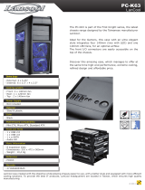 Lancool PC-K63 Datasheet
-
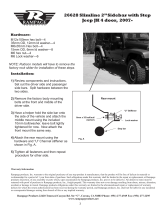 RAMPAGE PRODUCTS 26628 Installation guide


