Garland MSTSR16 Operating instructions

Category
Cookers
Type
Operating instructions

This manual is also suitable for

Users are cautioned that maintenance and repairs must be performed by a Garland authorized service agent
using genuine Garland replacement parts. Garland will have no obligation with respect to any product that has been
improperly installed, adjusted, operated or not maintained in accordance with national and local codes or installation
instructions provided with the product, or any product that has its serial number defaced, obliterated or removed,
or which has been modified or repaired using unauthorized parts or by unauthorized service agents.
For a list of authorized service agents, please refer to the Garland web site at http://www.garland-group.com.
The information contained herein, (including design and parts specifications), may be superseded and is subject
to change without notice.
GARLAND COMMERCIAL INDUSTRIES
185 East South Street
Freeland, Pennsylvania 18224
Phone: (570) 636-1000
Fax: (570) 636-3903
GARLAND COMMERCIAL RANGES, LTD.
1177 Kamato Road, Mississauga, Ontario L4W 1X4
CANADA
Phone: 905-624-0260
Fax: 905-624-5669
Enodis UK LTD.
Swallow eld Way, Hayes, Middlesex UB3 1DQ ENGLAND
Telephone: 081-561-0433
Fax: 081-848-0041
Part # P143 (11/10/08) © 2005 Garland Commercial Industries, Inc.
FOR YOUR SAFETY:
DO NOT STORE OR USE GASOLINE
OR OTHER FLAMMABLE VAPORS OR
LIQUIDS IN THE VICINITY OF
THIS OR ANY OTHER
APPLIANCE
WARNING:
IMPROPER INSTALLATION, ADJUSTMENT,
ALTERATION, SERVICE OR MAINTENANCE
CAN CAUSE PROPERTY DAMAGE, INJURY,
OR DEATH. READ THE INSTALLATION,
OPERATING AND MAINTENANCE
INSTRUCTIONS THOROUGHLY
BEFORE INSTALLING OR
SERVICING THIS EQUIPMENT
PLEASE READ ALL SECTIONS OF THIS MANUAL
AND RETAIN FOR FUTURE REFERENCE.
THIS PRODUCT HAS BEEN CERTIFIED AS
COMMERCIAL COOKING EQUIPMENT AND
MUST BE INSTALLED BY PROFESSIONAL
PERSONNEL AS SPECIFIED.
For Your Safety:
Post in a prominent location, instructions to be
followed in the event the user smells gas. This
information shall be obtained by consulting
your local gas supplier.
INSTALLATION AND
OPERATION MANUAL
MASTER SENTRY
GAS-OPERATED
SALAMANDER
Part # P143 (11/10/08)Page 2
IMPORTANT INFORMATION
WARNING:
This product contains chemicals known to the state of California to cause cancer and/or birth defects
or other reproductive harm. Installation and servicing of this product could expose you to airborne
particles of glass wool/ceramic fibers. Inhalation of airborne particles of glass wool/ceramic fibers
is known to the state of California to cause cancer. Operation of this product could expose you to
carbon monoxide if not adjusted properly. Inhalation of carbon monoxide is known to the state of
California to cause birth defects or other reproductive harm.
Keep appliance area free and clear of combustibles.
Part # P143 (11/10/08) Page 3
TABLE OF CONTENTS
IMPORTANT INFORMATION.............2
DIMENSIONS AND SPECIFICATIONS .....4
Model Designation ...........................4
Sux Denitions .............................4
Table A: Exterior Dimensions . . . . . . . . . . . . . . . . . 5
Table B: Gas Flow Rate Per Model . . . . . . . . . . . . . 5
Table C: Nominal Heat Input (Gross)
Per Model . . . . . . . . . . . . . . . . . . . . . . . . . . . . . . . . . . . 5
Table D: Setting Pressure / Injector Size . . . . . . . 5
Table E: Setting Pressure For “MIN”
Tap Position . . . . . . . . . . . . . . . . . . . . . . . . . . . . . . . . . 5
Table F: Pilot Flame Length . . . . . . . . . . . . . . . . . . . 6
Table G: Australian Nominal Gas
Consumption & Injector Size ..................6
INTRODUCTION........................6
Uncrating ....................................6
Product Application ..........................6
Optional Extras . . . . . . . . . . . . . . . . . . . . . . . . . . . . . . 6
Rating Plate ..................................6
INSTALLATION .........................7
General Installation . . . . . . . . . . . . . . . . . . . . . . . . . . 7
Clearances ...................................7
Siting ........................................7
Ventilation Air . . . . . . . . . . . . . . . . . . . . . . . . . . . . . . . 7
Statutory Regulations . . . . . . . . . . . . . . . . . . . . . . . . 7
COMMISSIONING ......................8
Burner Adjustments ..........................8
Gas Connection ..............................8
Gas Supply . . . . . . . . . . . . . . . . . . . . . . . . . . . . . . . . . . 8
OPERATION............................9
Safety concerns ..............................9
Lighting The Salamander .....................9
Operating Suggestions .......................9
CLEANING AND MAINTENANCE ........10
Daily Cleaning . . . . . . . . . . . . . . . . . . . . . . . . . . . . . . 10
Stainless Steel . . . . . . . . . . . . . . . . . . . . . . . . . . . . . . 10
Operating Controls. . . . . . . . . . . . . . . . . . . . . . . . . . 10
SERVICING............................11
Infrared Burners . . . . . . . . . . . . . . . . . . . . . . . . . . . . 11
Gas Taps ....................................11
Safety Equipment Check . . . . . . . . . . . . . . . . . . . . 11
REPLACEMENT OF PARTS..............11
Gas Taps ....................................11
Infrared Burners . . . . . . . . . . . . . . . . . . . . . . . . . . . . 11
Pilot Burner/Thermocouple. . . . . . . . . . . . . . . . . . 11
CONVERSION INSTRUCTIONS ..........12
TROUBLESHOOTING ..................13
SAFETY...............................13
Part # P143 (11/10/08)Page 4
DIMENSIONS AND SPECIFICATIONS
Model Designation
MODEL DESCRIPTION
MSTSRC 864 mm wide x 414 mm high, infra-red counter mount salamander.
MSTSR16-280 864 mm wide x 1089 mm high, infra-red restaurant range mount salamander.
MSTSR16 864 mm wide x 1089 mm high, infra-red heavy duty range mount salamander.
Sux Denitions
MST SRC, SR16-280, SR16
SRC - Counter Top Version
SR16-280 - Restaurant Range Mount Version
SR16 - Heavy Duty Range Mount Version
Base Model Number
16 5/16"
[414mm]
34"
[864mm]
17 61/64"
[456mm]
16 13/16"
[427mm]
20 1/4"
[514mm]
Part # P143 (11/10/08) Page 5
DIMENSIONS AND SPECIFICATIONS Continued
Table A: Exterior Dimensions
MODEL
HEIGHT WIDTH DEPTH WEIGHT
mm ins mm ins mm ins kg lb
MSTSRC 414 16.513 864 34 514 20.25 70.3 155
MSTSR16 414 16.513 864 34 514 20.25 95.3 210
Table B: Gas Flow Rate Per Model
MODEL
NATURAL GAS (m
3
/h) PROPANE GAS (kg/h)
G20 @ 20mbar G31 @ 37/50 mbar
MSTSRC 0.88 0.598
MSTSR16 0.88 0.598
Table C: Nominal Heat Input (Gross) Per Model
MODEL
(G20 @ 20 mbar) NATURAL GAS (G31 @ 37/50 mbar) PROPANE
Nominal Heat Input (Gross) Nominal Heat Input (Gross)
kW BTU/HR MJ/HR kW BTU/HR MJ/HR
MSTSRC 9.23 31,500 33.23 8.35 28,500 30.1
MSTSR16 9.23 31,500 33.23 8.35 28,500 30.1
Table D: Setting Pressure / Injector Size
MODEL/
SECTION
(G20 @ 20 mbar) Natural Gas (G31 @ 37/50 mbar) Propane
Setting Pressure Injector Size Setting Pressure Injector Size
mbar “W.C. I.D # mm mbar WC I.D. # mm
ALL 20 8 1.6 1.6
37 14.9 1.1 1.1
50 20 61 0.99
NOTE: The pressure must be measured at the pressure test nipple located on the main manifold pipe with all burners lit.
Table E: Setting Pressure For “MIN” Tap Position
MODELS
2ND Family, Group H 3RD Family, Group 3P
(G20 @ 20 mbar) NAT. GAS (G31 @ 37/50 mbar) PROPANE
mbar W.C. mbar W.C.
MSTSRC 10.5 4.2 23 9.4
MSTSR16 10.5 4.2 23 9.4
Part # P143 (11/10/08)Page 6
Table F: Pilot Flame Length
MODEL
PILOT FLAME LENGTH
mm ins.
MSTSRC/MSTSR16 25.4 1.0
Table G: Australian Nominal Gas Consumption & Injector Size
MODEL
Natural Gas Propane Gas
Injector Dia.
mm
Consumption
MJ/Hr.
Gas Pressure
KPA
Injector Dia.
mm
Consumption
MJ/Hr.
Gas Pressure
KPA
MSTSRC 2.4 21 1 1.4 21 2.5
DIMENSIONS AND SPECIFICATIONS Continued
INTRODUCTION
IMPORTANT: The following instructions should be read
carefully before attempting to operate the appliance. The
manufacturer cannot be held responsible for any damage
to property, persons or animals caused by incorrect
installation or operation of the appliance.
You have purchased the nest commercial cooking
equipment available. Like any other ne, precision built
piece of equipment it should be given regular care and
maintenance.
It is required by law that all gas appliances are installed by
competent persons in accordance with the LOCAL GAS
SAFETY REGULATIONS. Failure to install appliances correctly
can lead to prosecution. It is in your own interests and that of
safety to insure that there is compliance with the law.
Your Garland dealer is well qualied to provide this service.
Periodic inspections by your dealer or a qualied service
company are recommended to check temperatures, burner
adjustments and ensure moving parts are operative.
Wherever possible avoid overheating idle equipment, as this
is the primary cause for increased service cost.
“Regular Maintenance Ensures Peak Performance.
Uncrating
Check crate for possible damage sustained during transit.
Carefully remove unit from crate and again check for
damage. Any damage to the appliance must be reported to
the carrier immediately.
Product Application
The Garland infra-red salamander oers broiling for a wide
variety of products such as steak, lobster, sh, onion soup,
casseroles, garlic bread and hamburgers. The over-re infra-
red design provides for quick preheat and ecient, uniform
production. The tilting rack feature allows for an easy view
broiling.
Optional Extras
• Wallmountaccessories.
Rating Plate
The data plate is readily accessible, located behind the drip
tray. It contains all of the pertinent information required by
the installer.
The type of gas and the supply pressure that the equipment
was set up for at the factory is noted on the data plate and on
the packaging. This type of gas supply must be used.
In the event you have any questions concerning the
installation, use care or service of this or any other Garland
product, write or call our Product Service Department. When
corresponding with the factory or your equipment dealer
regarding service problems or replacement parts, be sure
to refer to the particular unit by the correct model number
(including prex and sux letters and numbers) and the
serial or code number. The rating plate axed to the unit
contains this information.
Part # P143 (11/10/08) Page 7
For proper operation, the Fuel information on the data plate
of you new equipment must match your fuel supply.
INSTALLATION
General Installation
1. Carefully remove unit from carton. All packing material
must be removed from the unit. The wires for retaining
the burners & other packing material must be removed
from unit. On stainless steel units, the protective
material covering the stainless steel must be removed
immediately after unit is installed.
NOTE: Do not remove permanently axed labels, warnings
or data plates from the appliance, for this may invalidate the
manufacturers warranty.
2. Place the appliance in the required position and level by
means of the levelling feet.
3. Connect the gas supply pipe work to the appliance. The
connection is made to the rear right hand side of the
appliance.
NOTE: A gas isolation cock must be tted in the supply
to the appliance. The gas isolation cock must be sited in a
position which is easily accessible to the user.
Clearances
The space in which the appliance is to be sited must include
the minimum installation clearances to combustible surfaces
shown in the following table.
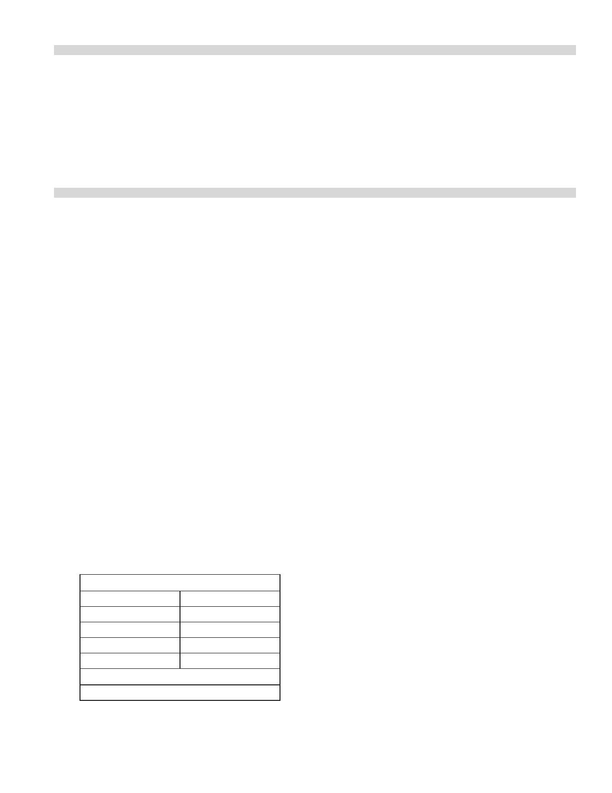
MINIMUM INSTALLATION CLEARANCES
Surface All Models
Top 1219mm (48 in.)
Left Hand Side 152mm (6 in.)
Right Hand Side 152mm (6 in.)
Rear 152mm (6 in.)
TYPE OF FLOOR OR BASE
Combustible
Siting
The unit should be installed on a rm, smooth and level
base capable of adequately supporting the weight of the
appliance and any ancillary equipment. (Refer to table A for
weight specications). Any openings in the wall behind or
beside the appliance must be sealed. Once in position check
that the unit is level, both front to back and side to side.
Adjust if necessary using the leveling feet on the four corners
of the tted legs.
Ventilation Air
The area in which the appliance is installed must be
adequately ventilated to provide air for combustion, removal
of products of combustion, etc. The use of a mechanical
extract system should be considered
The following notes are intended to give general guidance.
For detailed recommendations, refer to the applicable
code(s) in the Country of destination.
1: The room containing the appliance is required to have a
permanent air vent. The minimum eective area of the
vent is related to the maximum rated heat input of the
appliance and shall be 4.5 cm
2
per kW in excess of 7 kW.
2: Air vents should be of such a size to compensate for the
eects of any extract fan in the premises.
Statutory Regulations
The installation of this appliance must be carried out by
a competent person and in accordance with the relevant
regulations, standards, codes of practice and the related
publications of the Country of destination.
AUSTRALIA SPECIFIC CLAUSE This appliance must be
installed in accordance with the manufacturers instructions,
local gas tting regulations and requirements of AS 5601 /
AG 601 installation code. All burner adjustments and settings
should be made by a qualied gas technician.
INTRODUCTION continued
Part # P143 (11/10/08)Page 8
Gas Connection
The type of gas and the supply pressure that the equipment
was set up for at the factory is noted on the data plate and on
the packaging. This type of gas supply must be used.
The gas pipe connection is made at the right hand side of
the equipment. The size of the pipe work supplying the
appliance must not be less than the inlet connection which
is ISO 7/R 1/2”. An isolating cock is required to be close to
the appliance to allow shut down during an emergency or
routine servicing. After installation, the complete pipe work
must be checked for soundness.
Gas Supply
The local gas region should be consulted at the installation
planning stage in order to establish the availability of an
adequate supply of gas and to ensure that the meter is
adequate for the required ow rate. The pipe work from
the meter to the appliances must be of an appropriate size.
Where a number of appliances are installed in a battery, no
more than ve should be served by any one supply pipe.
INSTALLATION Continued
All xed ( non mobile ) appliances MUST be tted with a
manual gas cock upstream of the appliance to provide a
means of isolation for servicing or cleaning purposes. A
union or similar means of disconnection must be provided
between the gas cock and the appliance.
A manually operable valve must be tted to the gas supply
to the kitchen to enable it to be isolated in an emergency.
Wherever practical, this shall be located either outside the
kitchen or near to an exit in a readily accessible position.
Where it is not practical to do this, an automatic isolation
valve system shall be tted which can be operated from a
readily accessible position near to the exit.
At locations where the manual isolation valve is tted or
the automatic system can be reset a notice MUST be tted
stating:
All downstream burner and pilot valves must be turned
o prior to attempting to restore the supply. After
extended shut o, purge before restoring gas.
COMMISSIONING
The whole of the gas installation, including the meter,
should be inspected, purged and tested for soundness in
accordance with the codes of the Country of destination.
1. Ensure that all controls are in the position and turn
on the main gas supply and electrical mains.
2. Remove the drip tray and roll out rack assembly and
connect a U-gauge manometer to the pressure test
point on the main manifold. Operate the main burners in
accordance with the instructions given in the Operation
section.
3. Check that the setting pressure is correct per TABLE D. If
necessary, adjust the supply pressure to give the required
setting.
Burner Adjustments
Minimum Flame Setting
1. Set the gas tap to the low position.
2. Connect a U-gauge manometer to the pressure test
nipple located downstream of the gas tap.
3. With a at screwdriver, turn the adjuster on the tap body
clockwise to reduce pressure or counter-clockwise to
increase pressure. Set the pressure to correspond with
TABLE E.
Part # P143 (11/10/08) Page 9
OPERATION
Safety concerns
It is the responsibility of the supervisor or equivalent
person to ensure that users of this equipment wear suitable
protective clothing and to draw attention to the fact that
some parts will by necessity become very hot and will cause
burns if touched accidentally.
Lighting The Salamander
NOTE: Ensure the gas supply to the appliance is turned “ON”.
During the initial ignition cycle, air must be purged from the
gas line and thus it may take one to two minutes for the pilot
burner to ignite.
1. Push in the tap and turn it counter-clockwise to the
Ignition Position ”.
2. Holding the tap fully in, light the pilot with a match or
taper.
3. When the pilot is lit, continue to hold the tap fully in for
20 seconds, then release it. IF the pilot goes out, wait for
ve (5) minutes, and then repeat from step 1.
4. When the pilot is established, push the tap in again and
turn it counter-clockwise to the full ame position
thus lighting the main burner.
5. For low ame or simmer, push the tap in and turn it
counter-clockwise to the low ame position.
6. To shut the burner o, turn the dial to the symbol and
the safety device will disengage within 60 seconds.
Operating Suggestions
1. Turn the tap to the position when the salamander is
not in use.
2. Clean the racks as soon as possible after cooking with
tomato or vinegar based products that have a high acid
content. These foods can cause pitting of the rack surface.
3. Allow the salamander to preheat before adding product.
4. Drain and clean the drip tray frequently. Excessive oil
drain o in the pan can cause spillover.
Pilot
Adjuster
Low Flame
Adjuster
T
est Point
When all the settings have been checked, remove the
U-gauge manometer, replace the pressure test point screw
and the front panel.
Hand these instructions to the user or purchaser for retention
and instruct them in the ecient and safe operation of the
appliance.
Tell the user of the location of the gas isolation cock for use in
an emergency.
COMMISSIONING Continued
Part # P143 (11/10/08)Page 10
Operating Controls
OFF
IGNITION
MAX
MIN
OFF
IGNITION
MAX
MIN
OPERATION continued
CLEANING AND MAINTENANCE
Daily Cleaning
A regular daily cleaning schedule should be followed to
maintain your broilers ecient performance and minimize
service calls. At the end of each days use, the following steps
are recommended:
1. Remove and clean grid rack.
2. With the rack removed clean the interior of the unit with
a damp cloth.
3. Wipe exposed cleanable surfaces with a mild detergent
and hot water. Stubborn residue may be removed with a
lightweight non-metallic scouring pad.
4. Clean out grease drawer and wash thoroughly in hot
soapy water. Dry thoroughly.
Stainless Steel
Stainless steel should be cleaned using a mild detergent, a
soft cloth and hot water. If is necessary to use a non-metallic
scouring pad, always rub in the direction of the grain in the
metal to prevent scratching. Wash a small area at a time and
rinse the washed area with a clean sponge dipped into a
disinfectant and wipe dry with a soft cloth before it can dry.
Use only stainless steel, wood or plastic tools to scrape
o heavy deposits of grease or oil. Do not use ordinary
steel scrapers or knives, as particles of iron may become
embedded and rust. NEVER USE STEEL WOOL.
Part # P143 (11/10/08) Page 11
SERVICING
To ensure ecient and safe operation of the appliance it
is recommended that servicing be carried out at regular
interval, the frequency of which will vary, depending on the
installation. Servicing must be carried out by competent
persons in accordance with the law.
WARNING: Turn o the gas supply to the appliance at the
service cock and the electrical mains before commencing
any servicing work.
IMPORTANT: Test for gas soundness on completion of any
servicing work.
Infrared Burners
Support the burner with one hand while removing the two
(2) acorn nuts from the top of the unit securing the main
burner. Allow burner to drop and remove through the front
opening. Check the burner tiles and wire mesh for soot or
blocked ports. Clean with a damp cloth if required.
Gas Taps
Re-greasing of the taps is not recommended. If the tap
spindles become seized or dicult to turn, refer to the
Replacement of parts section in this manual.
Safety Equipment Check
Check the operation of all thermocouples and ame safety
devices by lighting the pilots individually and then blowing
them out. Listen for the ame failure valve clicking closed.
This action must occur within 60 seconds of extinguishing
the pilot.
REPLACEMENT OF PARTS
WARNING: Turn o the gas supply to the appliance at the
service cock before commencing any servicing work.
IMPORTANT: Test for gas soundness on completion of any
servicing work.
Servicing must be carried out by competent persons in
accordance with the law.
Gas Taps
1. Pull the control knob o each tap and remove the drip
tray and the roll out rack assembly.
2. Remove the four (4) screws (top & bottom) securing the
front fascia and remove the fascia panel to access the
multifunctional controls.
3. Disconnect the thermocouple connection at the rear of
the gas tap.
4. Disconnect the pilot and main burner tubing connections
at the gas tap.
5. Break the compression nut at the inlet of the gas tap and
replace the tap.
6. Reassemble in the reverse order.
Infrared Burners
Refer to the Servicing section for instructions on burner
removal.
Pilot Burner/Thermocouple
1. Remove the main burner following the procedure given
under Servicing.
2. Remove the four (4) screws (top & bottom) securing the
front fascia and remove the fascia panel to access the
multifunctional control.
3. Disconnect the thermocouple connection at the rear of
the gas tap.
4. Disconnect the pilot tube connection/thermocouple
connection at the gas tap.
5. Remove the two (2) screws that secure the pilot
mounting bracket to the side liner and remove the pilot
burner/thermocouple.
6. Replace the faulty component and reassemble in the
reverse order.
Part # P143 (11/10/08)Page 12
CONVERSION INSTRUCTIONS
Servicing must be carried out by a competent person in
accordance with the law.
WARNING: Turn o the gas supply to the appliance at the
service cock before commencing any servicing work.
IMPORTANT: Test for gas soundness on completion of any
servicing work.
The following instructions are intended to describe the
operations necessary to convert equipment from operation
on one gas family to that of another.
1. Ensure that all of the parts necessary to make the
conversion have been supplied as follows:
a. Injector ttings (One required for each main burner).
b. Pilot injector ttings (One required per pilot burner).
c. Gas adjustment label (One required per unit).
If any of the required parts are missing, contact your Garland
dealer before attempting to carry out the conversion.
NOTE: Conversion kits supplied for G31 gas will contain
redundant ttings and markings covering both 37 mbar & 50
mbar gas supplies.
2. Remove the burners following the instructions given in
this manual.
3. Replace each injector tting with the new tting that is
supplied.
NOTE: Before doing so, refer to Table D (Table G for Australian
Models) in this manual to ensure that the correct injector has
been supplied for the gas supply being converted to.
4. Replace each pilot injector tting with the new tting
supplied.
Ensure that you have the correct pilot injector before
replacing.
Upon completion of all the above operations, follow the
section in the manual on “Commissioning and ensure
that the setting pressure and all burner ame settings are
adjusted accordingly.
Continuous product improvement is a Garland policy,
therefore specications and design are subject to change
without notice.
Part # P143 (11/10/08) Page 13
TROUBLESHOOTING
PROBLEM POSSIBLE CAUSE SOLUTION
Burner ame too large. Incorrect setting pressure or injector. Check setting pressure and injector.
Burner ame soft - yellow tip. Insucient primary air. Check primary aeration for blockage.
Delayed Ignition Pilot burner ame too small. Check pilot ame adjustment.
Burner ports blocked. Clean blocked burner ports.
Incorrect setting pressure. Check setting pressure.
Pilot Burner will not ignite Pilot orice blocked. Clean pilot jet.
Pilot adjusting screw closed. Open pilot adjuster.
Pilot Keeps Extinguishing. Pilot ame too small. Check pilot.
Loose thermocouple connection. Tighten connection.
Faulty thermocouple. Replace thermocouple.
Faulty ame safety device. Replace ame safety device.
Low millivolt output on
open circuit test.
Pilot ame too small. Adjust pilot ame length.
Defective thermocouple. Replace thermocouple.
Millivolt output high in open circuit test
but low in closed circuit test.
Faulty ame safety device. Replace ame safety tap.
Millivolt output high on closed circuit
test but ame safety tap will not stay
open.
Faulty ame safety device. Replace ame safety tap.
SAFETY
It is essential that the instructions in this booklet are strictly
followed for the safe and economical operation of the
equipment. If it is known or suspected that a fault exists on
the appliance then it must not be used until the fault has
been rectied by a competent person.
Part # P143 (11/10/08)Page 14
Part # P143 (11/10/08) Page 15
  • Page 1 1
  • Page 2 2
  • Page 3 3
  • Page 4 4
  • Page 5 5
  • Page 6 6
  • Page 7 7
  • Page 8 8
  • Page 9 9
  • Page 10 10
  • Page 11 11
  • Page 12 12
  • Page 13 13
  • Page 14 14
  • Page 15 15
  • Page 16 16

Garland MSTSR16 Operating instructions

Category
Cookers
Type
Operating instructions
This manual is also suitable for

Ask a question and I''ll find the answer in the document

Finding information in a document is now easier with AI