
F.01U.269.830 Rev 20 06/2012
KP 812 Keypanel
Desktop with Handset, Desktop,
Rack Mount and Lever Key
User Manual

PROPRIETARY NOTICE
The product information and design disclosed herein were originated by
and are the property of Bosch Security Systems, Inc. Bosch reserves all
patent, proprietary design, manufacturing, reproduction, use and sales
rights thereto, and to any article disclosed therein, except to the extent
rights are expressly granted to others.
COPYRIGHT NOTICE
Copyright 2012 by Bosch Security Systems, Inc. All rights reserved.
Reproduction, in whole or in part, without prior written permission from
Bosch is prohibited.
*All other trademarks are property of their respective owners.
WARRANTY AND SERVICE INFORMATION
For warranty and service information, refer to the appropriate web site
below:
RTS Intercoms ......................................www.rtsintercoms.com/warranty
RTS Digital
RTSTW
AudioCom
RadioCom..........................................www.telexradiocom.com/warranty
Headsets........................................www.intercomheadsets.com/warranty
CUSTOMER SUPPORT
Technical questions should be directed to:
Customer Service Department
Bosch Security Systems, Inc.
12000 Portland Avenue South
Burnsville, MN 55337 USA
Telephone: 877-863-4169
Fax: 800-323-0498
TECHNICAL QUESTIONS EMEA
Bosch Security Systems Technical Support EMEA
http://www.rtsintercoms.com/contact_main.php
DISCLAIMER
The manufacturer of the equipment described herein makes no
expressed or implied warranty with respect to anything contained
in this manual and shall not be held liable for any implied
warranties of fitness for a particular application or for any
indirect, special, or consequential damages. The information
contained herein is subject to change without prior notice and
shall not be construed as an expressed or implied commitment on
the part of the manufacturer.
THE LIGHTNING
FLASH AND
ARROWHEAD
WITHIN THE
TRIANGLE IS A
WARNING SIGN
ALERTING YOU OF
“DANGEROUS
VOLTAGE” INSIDE
THE PRODUCT.
CAUTION: TO REDUCE
THE RISK OF ELECTRIC
SHOCK, DO NOT REMOVE
COVER. NO USER-
SERVICABLE PARTS
INSIDE. REFER
SERVICING TO
QUALIFIED SERVICE
PERSONNEL.
THE EXCLAMATION
POINT WITHIN THE
TRIANGLE IS A
WARNING SIGN
ALERTING YOU OF
IMPORTANT
INSTRUCTIONS
ACCOMPANYING
THE PRODUCT.
SEE MARKING ON BOTTOM/BACK OF PRODUCT.
WARNING: APPARATUS SHALL NOT BE EXPOSED TO DRIPPING OR
SPLASHING AND NO OBJECTS FILLED WITH LIQUIDS, SUCH AS VASES,
SHALL BE PLACED ON THE APPARATUS.
WARNING: THE MAIN POWER PLUG MUST REMAIN READILY OPERABLE.
CAUTION: TO REDUCE THE RISK OF ELECTRIC SHOCK, GROUNDING OF
THE CENTER PIN OF THIS PLUG MUST BE MAINTAINED.
WARNING: TO REDUCE THE RISK OF FIRE OR ELECTRIC SHOCK, DO NOT
EXPOSE THIS APPRATUS TO RAIN OR MOISTURE.
WARNING: TO PREVENT INJURY, THIS APPARATUS MUST BE SECURELY
ATTACHED TO THE FLOOR/WALL/RACK IN ACCORDANCE WITH THE
INSTALLATION INSTRUCTIONS.
This product is AC only.

Important Safety Instructions
1. Read these instructions.
2. Keep these instructions.
3. Heed all warnings.
4. Follow all instructions.
5. Do not use this apparatus near water.
6. Clean only with dry cloth.
7. Do not block any ventilation openings. Install in accordance with the
manufacturer’s instructions.
8. Do not install near any heat sources such as radiators, heat registers, stoves, or
other apparatus (including amplifiers) that produce heat.
9. Do not defeat the safety purpose of the polarized or grounding-type plug. A
polarized plug has two blades with one wider than the other. A grounding type
plug has two blades and a third grounding prong. The wide blade or the third
prong are provided for your safety. If the provided plug does not fit into your
outlet, consult an electrician for replacement of the obsolete outlet.
10. Protect the power cord from being walked on or pinched particularly at plugs,
convenience receptacles, and the point where they exit from the apparatus.
11. Only use attachments/accessories specified by the manufacturer.
12. Use only with the cart, stand, tripod, bracket, or table specified by the
manufacturer, or sold with the apparatus. When a cart is used, use caution when
moving the cart/apparatus combination to avoid injury from tip-over.
13. Unplug this apparatus during lightning storms or when unused for long periods
of time.
14. Refer all servicing to qualified service personnel. Servicing is required when
the apparatus has been damaged in any way, such as power-supply cord or plug
is damaged, liquid has been spilled or objects have fallen into the apparatus, the
apparatus has been exposed to rain or moisture, does not operate normally, or
has been dropped.


Table
of
Contents
Bosch Security Systems, Inc.
User Manual
F.01U.269.830
Rev. 20
Important Safety Instructions ..............................................................................................................................3
INTRODUCTION .......................................................................................................................13
General Description ...............................................................................................................................13
Features ..................................................................................................................................................14
Options ...................................................................................................................................................14
Keypanel References ..............................................................................................................................15
Specifications .........................................................................................................................................19
INSTALLATION ........................................................................................................................23
Dip Switch Settings ................................................................................................................................23
Connections ............................................................................................................................................25
EXP and LCP Connectors .................................................................................................................................25
Frame Connector ...............................................................................................................................................25
Headset Connector .............................................................................................................................................26
Headset Microphone Gain Adjustment ..........................................................................................................26
Panel Microphone Connector ............................................................................................................................27
Panel Microphone Gain Adjustment .................................................................................................................27
Aux In ................................................................................................................................................................27
Microphone Preamplifier ...................................................................................................................................27
External Headset, Speaker Output, and Footswitch Input .................................................................................27
GPIO ..................................................................................................................................................................27
Relay 1 & 2 (A &B) ..........................................................................................................................................27
Coaxial Connection (CS-100 Coaxial System Interface) ..................................................................................28
Requirements ..................................................................................................................................................28
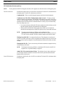
BASIC OPERATION ..................................................................................................................29
Selecting Headset or Speaker .................................................................................................................29
Listen Volume Adjustments ...................................................................................................................29
Listen Source Selection LED .........................................................................................................................29
Intercom Keys and Displays ..................................................................................................................31
Alphanumeric Display Indications for Intercom Keys ......................................................................................31
LED Indications for Intercom Keys ..................................................................................................................32
Intercom Key Operation .........................................................................................................................33
Basic Intercom Key Operation ..........................................................................................................................33
Operation of Intercom Keys with Auto Functions ............................................................................................33
Operation of Intercom Keys with Options ........................................................................................................34
Group Option Keys ........................................................................................................................................34

Bosch Security Systems, Inc.
User Manual
6 KP 812
Rev. 20
F.01U.269.830
Solo Key .........................................................................................................................................................34
Exclusive Key ................................................................................................................................................34
Operation of Intercom Talk Keys with Speaker DIM Setting ...........................................................................34
Operation of Intercom Keys Assigned to TIF Ports ..........................................................................................34
Muting the Microphone .........................................................................................................................34
Call Waiting Operation ..........................................................................................................................35
Addressing .............................................................................................................................................35
Determining the Keypanel Address for ADAM and ADAM CS Intercoms .................................................35
Determining the Keypanel Address for Zeus Intercom Systems ...................................................................35
Setting the Keypanel Address ...........................................................................................................................35
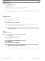
TELEPHONE OPERATION .....................................................................................................37
Receiving a Phone Call ..........................................................................................................................37
Dialing and Hanging Up Using the KP 812 Keypanel Dialing Menu ...................................................37
Manual Dialing ..................................................................................................................................................37
Redial .................................................................................................................................................................38
Autodial .............................................................................................................................................................38
KP 812 KEYPANEL MENU SYSTEM ......................................................................................39
Menu System, Menu Access ..................................................................................................................39
Menu System, Display Menu .................................................................................................................40
Display Menu, Assign Type ..............................................................................................................................40
Display Menu, Chan ON ...................................................................................................................................40
Display Menu, Key Groups ...............................................................................................................................40
Display Menu, Key List ....................................................................................................................................40
Display Menu, Level 2 ......................................................................................................................................40
Display Menu, Listen ........................................................................................................................................40
Display Menu, Matrix .......................................................................................................................................41
Display Menu, Panel ID ....................................................................................................................................41
Display Menu, Version ......................................................................................................................................41
Menu System, Key Assign Menu ..........................................................................................................41
General Procedure to Use the Key Assign Menu ..............................................................................................41
Key Assign Menu, Pt-to-Pt ...............................................................................................................................43
Key Assign Menu, Party Line ...........................................................................................................................43
Key Assign Menu, IFB ......................................................................................................................................43
Key Assign Menu, Spcl List ..............................................................................................................................43
Key Assign Menu, Sys Relay ............................................................................................................................43
Key Assign Menu, Camera ISO ........................................................................................................................43
Key Assign Menu, Quick Assign ......................................................................................................................43
Key Assign Menu, Reset Vols ..........................................................................................................................44
Menus .....................................................................................................................................................44
Menu, Autodial ..................................................................................................................................................44
Menu, Key Option Chime .................................................................................................................................44
Removing the chime option from a key. ........................................................................................................45
Menu, Key Option, Key Groups .......................................................................................................................45
Clearing a Key Group ....................................................................................................................................45
Menu, Key Option, Solo ....................................................................................................................................46
Removing the Solo Key Option .....................................................................................................................46
Menu, Key Option, Exclusive ...........................................................................................................................47
Removing the Exclusive Key Option .............................................................................................................47
Service Menu, Aux Inputs .................................................................................................................................47

Bosch Security Systems, Inc.
User Manual
Rev. 20
KP 812 7
F.01U.269.830
Service Menu, Baud Rate ..................................................................................................................................48
Service Menu, Dim ...........................................................................................................................................48
Service Menu, LCD Bright ...............................................................................................................................48
Service Menu, DSP Func ..................................................................................................................................49
Filtering ..........................................................................................................................................................49
Gating .............................................................................................................................................................49
Metering .........................................................................................................................................................50
Mixing ............................................................................................................................................................50
Service Menu, Handset .....................................................................................................................................50
Service Menu, LCP-16 ......................................................................................................................................51
Service Menu, Local GPIO ...............................................................................................................................51
Assigning an Input to Activate a Key ............................................................................................................51
Assigning an Input to Activate a Key Group .................................................................................................52
Removing an Input Assignment .....................................................................................................................52
Adding or Removing a GP Output Key Assignment .....................................................................................52
Service Menu, Matrix Out .................................................................................................................................53
Service Menu, Mic Select .................................................................................................................................53
Service Menu, Min Volume ..............................................................................................................................53
Service Menu, Speaker ......................................................................................................................................54
Service Menu, Mod Assign ...............................................................................................................................54
Service Menu, Output Level .............................................................................................................................55
Service Menu, Preamp Out ...............................................................................................................................56
Service Menu, Reset Cfg ...................................................................................................................................56
Service Menu, Save Cfg ....................................................................................................................................56
Service Menu, Sidetone .....................................................................................................................................56
Service Menu, Test Panel ..................................................................................................................................56
Service Menu, Tone Gen ...................................................................................................................................56
Service Menu, Tally Duration ...........................................................................................................................57
Special Functions ...................................................................................................................................57
Quick Assign .....................................................................................................................................................57
User Assignable Key .........................................................................................................................................57
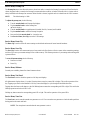
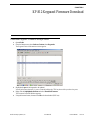
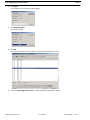
KP 812 KEYPANEL FIRMWARE DOWNLOAD ....................................................................59
Download Keypanel Firmware through AZedit ....................................................................................59
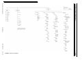
KP 812 MENU STRUCTURE QUICK REFERENCE .............................................................61
Menu Access ..........................................................................................................................................61
Menu Structure ......................................................................................................................................62
GLOSSARY .................................................................................................................................63
A .............................................................................................................................................................63
All Call ..............................................................................................................................................................63
Alpha .................................................................................................................................................................63
Auto Follow (AF) ..............................................................................................................................................63
Auto Functions ..................................................................................................................................................63
Auto Listen (AL) ...............................................................................................................................................63
Auto Mute (AM) ...............................................................................................................................................63
Auto Reciprocal (AR) .......................................................................................................................................64
Auto Table (AT) ................................................................................................................................................64

Bosch Security Systems, Inc.
User Manual
8 KP 812
Rev. 20
F.01U.269.830
C .............................................................................................................................................................64
Crosspoint ..........................................................................................................................................................64
D .............................................................................................................................................................64
Destination .........................................................................................................................................................64
Dim ....................................................................................................................................................................64
G .............................................................................................................................................................65
GPIO ..................................................................................................................................................................65
I ..............................................................................................................................................................65
IFB .....................................................................................................................................................................65
ISO (Camera ISO) .............................................................................................................................................65
M ............................................................................................................................................................66
Matrix ................................................................................................................................................................66
P .............................................................................................................................................................66
Party Line (PL) ..................................................................................................................................................66
Port ....................................................................................................................................................................67
R .............................................................................................................................................................67
Relay ..................................................................................................................................................................67
S .............................................................................................................................................................68
Special List ........................................................................................................................................................68
Stacked Key .......................................................................................................................................................68
T .............................................................................................................................................................68
Talk Level 1 .......................................................................................................................................................68
Talk Level 2 .......................................................................................................................................................68
Trunking ............................................................................................................................................................68
RVON-1 69
General Description of the RVON-1 Voice Over Network Card ..........................................................69
Features ..................................................................................................................................................69
Specifications .........................................................................................................................................70
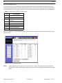
Default Addresses for the RVON Product Line ....................................................................................71
Dip Switches ..........................................................................................................................................71
Firmware Compatibility Requirements for the RVON-1 Card .............................................................71
Installation of the RVON-1 Card in a KP 812 .......................................................................................72
RVON-1 Relay ...............................................................................................................................................73
Addresses and the RVON-1 ...................................................................................................................74
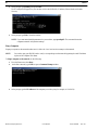
Configure the RVON-1 from the KP 812 ..............................................................................................75
TOP LEVEL MENU, SERVICE, RVON SETUP ............................................................................................75
Set the IP Address from the Service Level Menu ..........................................................................................75
TOP LEVEL MENU, RVON CONN. ..............................................................................................................76
Select an RVON Connection from the Top Level Menu ...............................................................................76
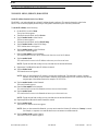
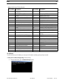
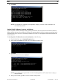
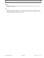
Configure the RVON-8 using AZedit to contact the RVON-1 .............................................................77
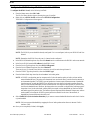
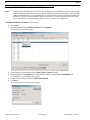
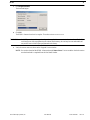
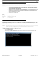
Download RVON-1 Firmware Through AZedit ...................................................................................78
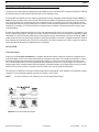
Basic Network Configuration ................................................................................................................80
LAN vs. WAN ...................................................................................................................................................80
Local Area Network .......................................................................................................................................80
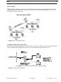
Wide Area Network .......................................................................................................................................81
Accessing The Wide Area Network (Wan) .......................................................................................................81
Network Address Translation (Nat) ..................................................................................................................82
Ports ...................................................................................................................................................................82
IP Addresses ......................................................................................................................................................83

Bosch Security Systems, Inc.
User Manual
Rev. 20
KP 812 9
F.01U.269.830
Ping a Computer ................................................................................................................................................84
Possible Pitfall With Routers, Gateways, And Switches ..................................................................................85
RVON Configuration .............................................................................................................................86
Network Terminology ............................................................................................................................87
Bridges ...........................................................................................................................................................87
Domain Name Server (DNS) .........................................................................................................................87
Gateway .........................................................................................................................................................87
Hub .................................................................................................................................................................87
IP Address ......................................................................................................................................................88
LAN ...............................................................................................................................................................88
Port .................................................................................................................................................................88
Routers ...........................................................................................................................................................88
Subnet .............................................................................................................................................................88
Switches .........................................................................................................................................................89
WAN ..............................................................................................................................................................89
RVON Serial and Telnet Commands .....................................................................................................90
Setup ..................................................................................................................................................................90
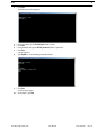
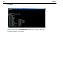
How to Configure the RVON-1 using Telnet ........................................................................................90

Bosch Security Systems, Inc.
User Manual
10 KP 812
Rev. 20
F.01U.269.830

List
of
Figures
Bosch Security Systems, Inc.
User Manual
F.01U.269.830
Rev. 20
FIGURE 1. Keypanel Reference Views ............................................................................................... 15
FIGURE 2. KP 812 Keypanel Board, DIP Switch Location ................................................................ 24
FIGURE 3. DE9S Intercom Cable Wiring ........................................................................................... 25
FIGURE 4. RJ-12 Intercom Cable Wiring ...........................................................................................26
FIGURE 5. Module Assignment Example ........................................................................................... 55
FIGURE 6. Menu List, Exploded ......................................................................................................... 62
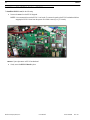
FIGURE 7. Spacer placement on KP 812 motherboard ....................................................................... 72
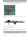
FIGURE 8. J2 Connector on the KP 812 Board ................................................................................... 73
FIGURE 9. The J37 connector on the KP 812 board ........................................................................... 73
FIGURE 10. Local Area Network Diagram ...........................................................................................80
FIGURE 11. Wide Area Network Diagram ........................................................................................... 81
FIGURE 12. Network Address Translation ........................................................................................... 81

Bosch Security Systems, Inc.
User Manual
F.01U.269.830
Rev. 20
12 KP 812

Bosch Security Systems, Inc.
User Manual
F.01U.269.830
Rev. 20
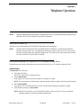
CHAPTER 1
Introduction
General Description
The RTS KP 812 keypanel fits in a standard 19” rack and is one (1) rack space high. It has 12 keys; one (1) listen button and
one (1) talk button make up a key. Ten keys are for intercom talk and listen, two keys are for call waiting response.
In addition, there are two (2) encoders. One (1) encoder is used for Headset, Microphone, Auxiliary Input, and Matrix In
volume adjustment. The other encoder knob is used for menu selection. The KP 812 keypanel has a standard numerical keypad
with four (4) extra keys: Mic Mute, User Assignable, Page Up, Page Down.
The KP 812 has a 8-character display panel. The KP 812 keypanels add significant new features such as digital signal
processing (DSP). The KP 812 keypanels also offer a custom design LCD display with support for 16x16 Kanji, Katakana,
Hiragana, and English characters.
The KP 812 keypanels are made of pressed aluminum/metal and feature state of the art audio processors and drivers. There are
four (4) different models of keypanel to choose between—Desktop, Desktop with Handset, Rack Mount, and
Rack Mount- Lever Key.

14 Introduction KP 812
Bosch Security Systems, Inc.
User Manual
F.01U.269.830
Rev. 20
Features
Options
Talk/Listen Configuration 12 keys, with 10 keys available for full talk/listen configuration. Keys support both
latching (hands-free) and momentary (push-to-talk) operation. Plus an extensive
scrollable menu system (accessed using an encoder). Menus include helpful prompts
to walk the user through setup.
Call Waiting Window The 11th and 12th display position are used as a call waiting window (CWW), while
the 12th key can be used for menu displays. The CWW is configured through the
menu. The user has three (3) assignable options from the menu, as follows:
1. No CWW
2. One CWW (12th key only)
3. Two CWW (11th and 12th key)
Character Display The LCD display is custom designed to show 16x16 size Japanese or Kanji
characters. Each LCD shows two (2) rows of 16-characters for a total of 32
characters. Each display area shows 8-character alphas per key (Talk/Listen).
NOTE: The KP 812 Keypanels have four (4) keys per display.
Hands-Free Button (Handset
Version Only)
The front panel of the handset version has a hands-free button. When this button is
active, the user is able to talk through a gooseneck mic and listen through the front
speaker.
Connections The back of each keypanel has one (1) DB-9 connector, one (1) RJ-12 connector, and
one (1) BNC for the matrix connection. On the rack mount model only, there is one
(1) RJ-12 connector for Expansion Panels and one (1) RJ-12 connector for an LCP.
There are two (2) mechanical pots for Mic Level Control, one (1) for Headset Mic
and one (1) for Panel Mic Gain.
NOTE: Only one (1) Matrix connection can be used at a time.
Firmware Every keypanel has an in-system downloadable firmware feature, where firmware is
downloaded through the AZedit application to the keypanels.
Configuration With the appropriate configuration, the KP 812 keypanel can be used as a digital
keypanel (sending and receiving digital audio from the matrix) or as an analog
keypanel. Digital operation is used when coaxial cables are used.
Remote Applications The KP 812 keypanel can be used in remote applications. The front panel can be
mounted separately and connected to the keypanel using up to a maximum of 50 feet
of cable.
Digital Signal Processing (DSP) Improves microphone voice activation and limiting. Adds new mixing, metering, and
filtering capabilities.
EKP-816 Provides additional 12 or 16 intercom keys.
LCP-12 or 16 Provides easy adjustment of point-to-point and party line listen levels for
individual intercom keys. One LCP-12 or LCP-16 controls volumes for one (1)
row of keys.

KP 812 Introduction 15
Bosch Security Systems, Inc.
User Manual
F.01U.269.830
Rev. 20
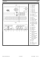
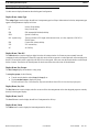
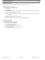
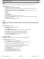
Keypanel References
Keypanel With Handset Model 1. Speaker LED
2. Headset LED
3. Matrix LED
4. AUX LED
5. Page 4 LED
6. Page 3 LED
7. Page 2 LED
8. Page 1 LED
9. Select/Menu Encoder
10. Volume Control
11. Mic Mute
12. Func
13. Page Up
14. Page Down
15. Panel Mic LED
16. Headset Mic LED
17. Panel Mic Connector
18. Standard Numerical
Keypad
19. Listen Keys
20. Display Panel
21. Talk Keys
22. Headset Connector
23. Hands-Free Switch
24. Handset RJ-11
Connector
25. Handset/Speaker
26. Headset Gain
27. Mic Gain
28. External Headset
Connector
29. Speaker/Footswitch
Connector
30. DB-9 Connector for
Matrix (frame)
31. RJ-12 Connector for
Matrix (frame)
32. Mic Out
33. Mic In
34. AUX In
35. Coax Connector
36. AC (power)
FIGURE 1. Keypanel Reference Views

16 Introduction KP 812
Bosch Security Systems, Inc.
User Manual
F.01U.269.830
Rev. 20
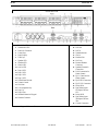
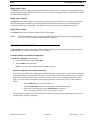
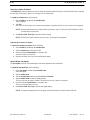
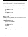
Desktop 1. Speaker LED
2. Headset LED
3. Matrix LED
4. AUX Led
5. Page 1 LED
6. Page 2 LED
7. Page 3 LED
8. Page 4 LED
9. Select/Menu Encoder
10. Volume Control
11. Mic Mute
12. User Assignable Key
13. Page Up
14. Page Down
15. Headset Connector
16. Panel Mic LED
17. Headset Mic LED
18. Panel Mic Connector
19. Standard Numerical
Keypad
20. Listen Keys
21. Display Panel
22. Talk Keys
23. Headset Gain
24. Mic Gain
25. External Headset
Connector
26. Speaker/Footswitch
Connector
27. DB-9 Connector for
Matrix (frame)
28. RJ-12 Connector for
Matrix (frame)
29. Mic Out
30. Mic In
31. Aux In
32. Coaxial Connector
33. AC (power)
FIGURE 1. Keypanel Reference Views

KP 812 Introduction 17
Bosch Security Systems, Inc.
User Manual
F.01U.269.830
Rev. 20
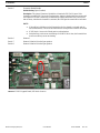
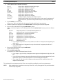
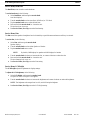
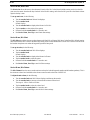
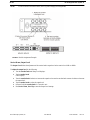
Rack Mount Model
1. Panel Mic LED
2. Headset Mic LED
3. Panel Mic Connector
4. Listen Keys
5. Panel Display
6. Talk Keys
7. Speaker LED
8. Headset LED
9. Matrix LED
10. Aux In LED
11. Page 4 LED
12. Page 3 LED
13. Page 2 LED
14. Page 1 LED
15. Select/Menu Encoder
16. Volume Control
17. Mic Mute
18. User Assignable Key
19. Page Up
20. Page Down
21. Standard Numerical Keypad
22. Headset Connector
23. AC
24. MIC Out
25. MIC In
26. Speaker/Monitor
27. Aux In
28. Headset Gain
29. Mic Gain
30. External Headset
Connector
31. Speaker/Footswitch
Connection
32. DB-9 Connection for
Matrix (frame)
33. RJ-11 Connection for
Matrix (frame)
34. RJ-45 EXP Connection
35. RJ-45 LCP Connection
36. Relay 1&2A
37. Opto-Isolate Input
1&2Open Collector
1&2
38. Relay 1&2B
39. Opto-Isolate Input
3&4Open Collector
3&4
40. Coaxial Connection
FIGURE 1. Keypanel Reference Views

18 Introduction KP 812
Bosch Security Systems, Inc.
User Manual
F.01U.269.830
Rev. 20
Controls Description
Speaker LED Indicates the user can adjust the speaker levels.
Headset LED Indicates the user can adjust the headset levels.
Matrix IN LED Indicates the user can adjust the audio levels from the Matrix to the keypanel.
Aux IN LED Indicates the user can adjust the audio levels from the Aux IN to the keypanel.
Page 4 LED When the Page 4 LED is lit, this indicates setup page four is assigned to the main panel.
Page 3 LED When the Page 3 LED is lit, this indicates the setup page three is assigned to the main
panel.
Page 2 LED When the Page 2 LED is lit, this indicates the setup page two is assigned to the main
panel.
Page 1 LED When the Page 1 LED is lit, this indicates the setup page one is assigned to the main panel.
Menu Encoder The menu encoder knob turns clockwise and counter-clockwise to scroll through menu
options. To select an option, tap the encoder key once. To go back one step, double-tap the
encoder knob. Press and hold for one second to exit.
Volume Control The volume control knob controls the volume of the selected source or destination, as
indicated by the lit LED.
Mic Mute The Mic Mute button mutes whichever microphone is active so no audio can be
transmitted through the microphone.
Func Key The Func Key is a user assignable key or softkey that can be programmed to perform an
action frequently used or is difficult to access, such as a lower level menu item. It can also
be programmed to operate a local GPI output.
Page Up and Down The Page Up button or Page Down button changes the active page assigned to the main
panel.
Panel Mic Connector Accepts an electret gooseneck microphone, such as the Telex model MCP-90-XX. The
model MCP-90 series panel mic connector is a 1/4” stereo plug, with a threaded shaft for
easy installation.
Panel Mic LED When the Panel Mic LED is lit green, the Panel Mic is active. This is the default setting
for the KP 812 Keypanel.
Headset Mic LED When the Headset Mic LED is lit green, the Headset Mic is active. This automatically
becomes active when a headset is plugged in.
Standard Numerical Keypad Use the keypad to enter autodial numbers, as well as dial an outside number for TIF
operation.
Listen Buttons The listen buttons allow the user to listen to audio coming into the keypanel. To listen,
press an upper button. A green LED lights the button.
Display Panel The 11th and 12th display positions are used as a call waiting window (CWW) and menu
display. The CWW is configured through the menu. The user has three (3) assignable
options from the menu, as follows:
1. No CWW
2. One CWW (12th key only)
3. Two CWW (11th and 12th key)
Talk Keys The talk buttons allow the user to talk to other keypanels. To talk, press a lower button. A
red LED lights the button.
Headset Connector The headset connector is a 4-pin XLR connector, which when plugged into the KP 812
keypanel, turns the panel mic off and audio is sent to the headset and the headset mic is
activated.

KP 812 Introduction 19
Bosch Security Systems, Inc.
User Manual
F.01U.269.830
Rev. 20
Specifications
Microphone Preamplifier
Electret Mic Input Level @ 1kHz
-42dB, 150 Ohms
Dynamic Mic Input Level @ 1kHz
-50dBm, 150 Ohms
Output Level (to Matrix)
+8dBu, ±0.2dBu
Max Voltage Gain, Mic to Line
70dB, ±2dB
Frequency Response
100Hz to 10kHz, ±2dB
Limiter
10dB above nominal
Tone Generator
Output Level (to Matrix)
+8dBu, ±2dBu
Output Frequency
500Hz
Headphone Amplifier
Maximum Voltage Gain
200dB
Frequency Response
100Hz to 10kHz, ±2dB
Headphone Impedance
8 to 600 Ohms
Output Power
1W to 50 Ohms
Output Voltage Level
8 volts peak-to-peak (max.)
Speaker Amplifier and Speaker
Frequency Response
100Hz to 10kHz, ±2dB
Output Power (per amplifier)
5 watt into 8 Ohms
Output Voltage Level
12 volts peak-to-peak
Volume Control Range
30dB
Speaker Rating
8 watts max.
Intercom Input/Output
Input
Nominal: +8dBu, Peak +20dBu max.
Output
+8dBu, ±2dBu max.
External Line Input (Program Input)
Input Level
+8dBu nominal
General
AC Supply
Internal switching type, 100–240VAC, 50/60Hz with
universal IEC connector for connection to various AC main
cords.
Storage
-40°C (-40°F) to 70°C (158°F)
Operating
-20°C (-4°F) to 60°C (140°F)
DIMENSIONS
Desktop
11.3(W) x 7.623(D) x 3.1(H)
Rack Mount
19(W) x 7.5(D) x 1.75(H)
Approvals
UL, CSA, VDE, CE
Connectors
Panel Mic Connector
Type: 3 circuit, 1/4” phone jack with threaded metal bushing,
compatible with RTS MCP-90
Pin Out
Tip: +Audio an DC bias
Ring: Common
Sleeve Chassis Ground

20 Introduction KP 812
Bosch Security Systems, Inc.
User Manual
F.01U.269.830
Rev. 20
Headset Connector
Type: XLR-4 Female
Pin 1 Mic low
Pin 2 Mic high
Pin 3 Headphone low
Pin 4 Headphone high
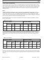
Intercom Connectors: Parallel-wired DE9S and RJ-12
Connectors
Type: DE9S
Pin 1 Data +
Pin 2 Data -
Pin 3 Audio In (from matrix) Shield
Pin 4 Audio Out (to matrix) +
Pin 5 Audio Out (to matrix) -
Pin 6 Data Shield
Pin 7 Audio In (from matrix) -
Pin 8 Audio In (from matrix) +
Pin 9 Audio Out (to matrix) shield
Type: RJ-12
Pin 1 Data -
Pin 2 Audio In (from matrix) +
Pin 3 Audio Out (to matrix) +
Pin 4 Audio Out (to matrix) -
Pin 5 Audio In (from matrix) -
Pin 6 Data +
Expansion Connector
Type: RJ-45
LCP Connector
Type: RJ-45
GPI Module Connectors (Optional)
Speaker/Monitor Output
Type: 5-pin XLR Male
Pin 1 Line Out (GND)
Pin 2 Line Out (+)
Pin 3 Line Out (-)
Pin 4 SPK Out (+)
Pin 5 SPK Out (-)
Aux 1 In (Auxiliary Program Input
3-pin XLR Female
Pin 1 Ground
Pin 2 Input +
Pin 3 Input -
Balance Input, +8dBu nominal
Relay 1 & 2 Output
Type: 9-pin male, D-sub
Pin 1 NC contact 1
Pin 2 COM contact 1
Pin 3 NO contact 1
Pin 4 NC contact 2
Pin 5 COM contact 2
Pin 6 NO contact 2
Pin 7 +3.3 VDC
Pin 8 Ground
Pin 9 +3.3 VDC
Relay 3 & 4 Output
Type: 9-pin male, D-sub
Pin 1 NC contact 3
Pin 2 COM contact 3
Pin 3 NO contact 3
Pin 4 NC contact 4
Pin 5 COM contact 4
Pin 6 NO contact 4
Pin 7 +3.3 VDC
Pin 8 Ground
Pin 9 +3.3 VDC
NOTE: The relay 1 and 3 contacts are electrically separate, but
operate in unison. The relay 2 and 4 contacts are
electrically separate, but operate in unison. The +3.3
VDC pins are connected internally through 1K resistors
to +3.3 VDC and can source 3mA. This voltage can be
used with the relay contacts to create an active high
output for some devices requiring a +3.3 VDC signal to
activate. For example, connecting pin 7 to pin 3 of the
Relay 1&2 connector results in +3.3 VDC on pin 2
when the relay is activated.
Page is loading ...
Page is loading ...
Page is loading ...
Page is loading ...
Page is loading ...
Page is loading ...
Page is loading ...
Page is loading ...
Page is loading ...
Page is loading ...
Page is loading ...
Page is loading ...
Page is loading ...
Page is loading ...
Page is loading ...
Page is loading ...
Page is loading ...
Page is loading ...
Page is loading ...
Page is loading ...
Page is loading ...
Page is loading ...
Page is loading ...
Page is loading ...
Page is loading ...
Page is loading ...
Page is loading ...
Page is loading ...
Page is loading ...
Page is loading ...
Page is loading ...
Page is loading ...
Page is loading ...
Page is loading ...
Page is loading ...
Page is loading ...
Page is loading ...
Page is loading ...
Page is loading ...
Page is loading ...
Page is loading ...
Page is loading ...
Page is loading ...
Page is loading ...
Page is loading ...
Page is loading ...
Page is loading ...
Page is loading ...
Page is loading ...
Page is loading ...
Page is loading ...
Page is loading ...
Page is loading ...
Page is loading ...
Page is loading ...
Page is loading ...
Page is loading ...
Page is loading ...
Page is loading ...
Page is loading ...
Page is loading ...
Page is loading ...
Page is loading ...
Page is loading ...
Page is loading ...
Page is loading ...
Page is loading ...
Page is loading ...
Page is loading ...
Page is loading ...
Page is loading ...
Page is loading ...
Page is loading ...
Page is loading ...
-
 1
1
-
 2
2
-
 3
3
-
 4
4
-
 5
5
-
 6
6
-
 7
7
-
 8
8
-
 9
9
-
 10
10
-
 11
11
-
 12
12
-
 13
13
-
 14
14
-
 15
15
-
 16
16
-
 17
17
-
 18
18
-
 19
19
-
 20
20
-
 21
21
-
 22
22
-
 23
23
-
 24
24
-
 25
25
-
 26
26
-
 27
27
-
 28
28
-
 29
29
-
 30
30
-
 31
31
-
 32
32
-
 33
33
-
 34
34
-
 35
35
-
 36
36
-
 37
37
-
 38
38
-
 39
39
-
 40
40
-
 41
41
-
 42
42
-
 43
43
-
 44
44
-
 45
45
-
 46
46
-
 47
47
-
 48
48
-
 49
49
-
 50
50
-
 51
51
-
 52
52
-
 53
53
-
 54
54
-
 55
55
-
 56
56
-
 57
57
-
 58
58
-
 59
59
-
 60
60
-
 61
61
-
 62
62
-
 63
63
-
 64
64
-
 65
65
-
 66
66
-
 67
67
-
 68
68
-
 69
69
-
 70
70
-
 71
71
-
 72
72
-
 73
73
-
 74
74
-
 75
75
-
 76
76
-
 77
77
-
 78
78
-
 79
79
-
 80
80
-
 81
81
-
 82
82
-
 83
83
-
 84
84
-
 85
85
-
 86
86
-
 87
87
-
 88
88
-
 89
89
-
 90
90
-
 91
91
-
 92
92
-
 93
93
-
 94
94


Ask a question and I''ll find the answer in the document
Finding information in a document is now easier with AI
Related papers
Other documents
-
Boulder 812 User guide
-
Telex Pam-32 User manual
-
LY International Electronics H-W02 Owner's manual
-
JK Audio Four IFB User manual
-
Chamberlain RIFMS2 User manual
-
Clear-Com SB-704 Owner's manual
-
-
-
-
Advantech Network Card ADAM 4000 User manual