
Packaged Dual Fuel Units
Owner's Guide to Operating and
Maintaining Your Dual Fuel Unit
ELECTRICAL SHOCK HAZARD.
Failure to follow this warning could result in
personal injury, death, and/or property damage.
Disconnect power at fuse box or service panel
before performing recommended maintenance.
FIRE, EXPLOSION, ELECTRICAL SHOCK
HAZARD.
Failure to follow this warning could result in
personal injury, death, and/or property damage.
Do not use this unit if any part has been under
water. Immediately call a qualified service
technician to inspect the unit and to replace any
part of the control system which has been under
water.
FIRE OR EXPLOSION HAZARD
Failure to follow safety warnings exactly could
result in serious injury, death, and/or property
damage.
--Information in this manual MUST be followed
exactly.
--Do not store or use gasoline or other flammable
vapors and liquids in the vicinity of this or any
other appliance.
--WHAT TO DO IF YOU SMELL GAS
• Leave the building immediately.
• Do not try to light any appliance.
• Do touch any electrical switch; do not use any
phone in the building.
• Immediately call your gas supplier from a
neighbors phone. Follow the gas suppliers
instructions.
• If you cannot reach your gas supplier, call the
fire department.
-- Installation and service must be performed by a
qualified installer, service agency or the gas
supplier.
This manual should be left with the owner.
Printed in U.S.A.
Code: PDX3 2/22/06 518 02 1601 O0

SAFETY CONSIDERATIONS
Installation and servicing of air-conditioning equipment
can be hazardous due to system pressure and electrical
components. Only trained and qualified personnel should
install, repair, or service air-conditioning equipment.
Untrained personnel can perform basic maintenance
functions of cleaning coils and filters. All other operations
should be performed by trained service personnel. When
working on air-conditioning equipment, observe
precautions in the literature, tags, and labels attached to
the unit, and other safety precautions that may apply.
Follow all safety codes. Wear safety glasses and work
gloves. Use quenching cloth for unbrazing operations.
Have fire extinguisher available for all brazing operations.
FIRE AND ELECTRICAL SHOCK HAZARD
TO LIGHT UNIT
Your combination heating/cooling unit is equipped with an
automatic direct spark ignition and power combustion
blower.
FIRE AND/OR EXPLOSION HAZARD
Failure to follow this warning could result in personal
injury, death, and/or property damage.
Do NOT attempt to light the pilot or burner with amatch
or flame of any kind.
Improper installation, adjustment, alteration, service,
maintenance, or use can cause fire or an explosion
which could result in personal injury or unit damage.
Consult a qualified installer, service agency, or gas
supplier for information or assistance. The qualified
installer or agency must use only factory-authorized kits
or accessories when modifying this product.
FIRE, AND ELECTRICAL SHOCK HAZARD
FIRE AND/OR EXPLOSION HAZARD
Failure to follow this warning could result in personal
injury, death, and/or property damage.
Do not turn off the electrical power to unit without first
turning off the gas supply.
Before attempting to start the gas heating section,
familiarize yourself with all the procedures that must be
followed.
Failure to follow this warning could result in personal
injury, death and/or property damage.
Before performing service or maintenance operations
on unit, turn off gas supply to unit. Then turn off unit main
power switch and install lockout tag.
Recognize safety information. This is the safety-alert
symbol_.V When you see this symbol in instructions or
manuals, be alert to the potential for personal injury.
Understand the signal words DANGER, WARNING,
CAUTION, and NOTE. These words are used with the
safety-alert symbol. DANGER identifies the most serious
hazards which will result in serious injury or death.
WARNING signifies a hazard which could result in serious
injury or death. CAUTION is used to identify unsafe
practices which may result in minor personal injury or
product and property damage. NOTE is used to highlight
suggestions which will result in enhanced installation,
reliability, or operation.
It is the personal responsibility and obligation of the
customer to contact a qualified installer to ensure that the
installation is adequate and conforms to governing codes
and ordinances.
UNIT DAMAGE HAZARD
Failure to follow this caution may result in the shorten
life of unit components.
Do NOT operate unit in a corrosive atmosphere
containing chlorine, fluorine, or any other corrosive
chemicals.
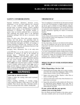
Refer to Figure 1 for gas valve location.
1. Set the temperature selector on room thermostat to the
lowest temperature setting and set system switch to
EMERGENCY HEAT or AUXILIARY HEAT,
2. Close the external manual shutoff valve.
3. Turn off the electrical supply to the unit.
4. Remove the front access panel with a 5/16 -in. nut
driver.
5. Move the selector switch on the internal gas valve to the
OFF position and wait 5 minutes.
6. Move the selector switch on the internal gas valve to the
ON position.
7. Replace the front access panel.
8. Turn on the electrical supply to unit.
9. Open the external manual shutoff valve.
10.
Set the temperature selector on room thermostat
slightly above room temperature to start unit. The
induced-draft combustion-air fan will start. Main gas
valve will open and burners should ignite the gas
within 25 seconds. If burners do not light within 25
seconds, the ignition control will go into a Retry Mode
that will take another 25 seconds. If the burners fail to
ignite the gas in 4 consecutive attempts, the unit will
lockout for 3 hours.
11. Set the temperature selector on room thermostat to
desired setting.
12. Return thermostat system switch to HEAT,

FIRE AND/OR EXPLOSION HAZARD
Failure to follow this warning could result in personal
injury, death, and/or property damage.
1. If the main burners fail to light, or the blower fails to
start, shut down gas heating section and call your
dealer for service.
2. Never attempt to manually light the main burners on
unit with a match, lighter, or any other flame. If the
electric sparking device fails to light the main burners,
refer to the following shutdown procedures, then call
your dealer as soon as possible.
TO SHUT UNIT OFF
FIRE AND/OR EXPLOSION HAZARD
Failure to follow this warning could result in personal
injury, death, and/or property damage.
Do not turn off the electrical power to unit without first
turning off the gas supply.
NOTE: If unit is being shut down because the heating
season has ended, make sure to turn on power to cooling
system,
If unit is being shut down because of a malfunction, call
your dealer as soon as possible.
Should the gas supply fail to shut off or if overheating
occurs, shut off the manual gas valve to the unit before
shutting off the electrical supply.
Do not use this furnace if any part has been under water. A
flood-damaged furnace is extremely dangerous. Attempts
to use the furnace can result in fire or explosion. A qualified
service agency should be contacted to inspect the furnace
and to replace all gas controls, control system parts,
electrical parts that have been wet or the furnace ifdeemed
necessary.
Refer to Fig. 1 while proceeding with the following steps.
1. Set the temperature selector on room thermostat to
lowest temperature setting and set system switch to
OFF.
2. Close the external manual shutoff valve.
3. Turn off the electrical power supply to the unit.
4. Remove the front access panel.
5. Move the selector switch on the internal gas valve to the
OFF position.
6. Replace the burner access panel.
7. Restore electrical power to the unit and set system
switch to COOL to ensure operation of the cooling
system during the cooling season.
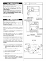
FigUre i J Access to Gas Valve
O©
i ISelector Leads
IRemote Sparker Unit i
i Primary LimitSwitch I
',\
L
I__
Flame Sensor I
!
I GasValveI ''
I Rolleut Switch I
I Gas Valve ]
RegulatorAdjustment
UnderCa
,NL
Inlet
Pressure
Tap 1/8 NPT
HONEYWELL
©o
Outlet
Pressure
Tap
1/sNPT
J
OUTLET
25-24-98a

EFFICIENT HEATING and COOLING
Your new unit is among the most energy-efficient and
reliable dual fuel products available today. To assure its
dependability, spend just a few minutes with this booklet
now. Learn about the operation of your dual fuel system
and the small amount of maintenance it takes to keep it
operating at its peak efficiency.
With minimal care, your dual fuel unit will provide you and
our family with satisfying home comfort - both now and for
ears to come.
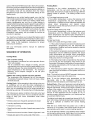
Minimum Clearances and Access Panels
(Small Chassis Shown)
Blower Compartment Panel
Small Chassis - 2"
Large Chassis -
30"
80"
80-00-01
Control Panel
accumulate around or on top ofthe unit. Maintain a 10-in.
minimum clearance between the outdoor unit and tall
grass, vines, shrubs, etc.
• Your multi-purpose indoor thermostat is the control
center for your dual fuel system. You should familiarize
yourself with its proper operation. Attempting to control
the system by other means - for instance, switching the
electrical supply power ON and OFF - may cause
damage to the unit.
• Thermostat "jiggling" causes rapid-cycling, which is
potentially damaging to the compressor. Do not move the
temperature selector on the thermostat for any reason for
at least 5 minutes after the compressor has shut off.
• You may find that you can maintain greater personal
comfort by running the fan continuously. Air pockets can
form due to the structure of the building, placement of
registers, etc. These air pockets may be too cool orwarm
for your liking. Continuous fan operation minimizes any
temperature differences. Also, systems equipped with
electronic air cleaners and/or humidifiers offer the added
benefits of having the air continuously cleaned
year-round, and humidified during the winter season.
• Your dual fuel system will remove humidity from your
home during the cooling season. After a few minutes of
operation, you should be able to see water trickle from the
condensate drain of the cooling coil. Check this
occasionally to be sure the drain system is not clogged.
Ofcourse, don't expect to see much drainage if you live in
a very dry environment.
OPERATING YOUR UNIT
IMPORTANT FACTS
To better protect your investment and to eliminate
unnecessary service calls, familiarize yourself with the
following facts:
FIRE, EXPLOSION, ELECTRICAL SHOCK HAZARD
Improper installation, adjustment, alteration, service,
maintenance or use could cause fire, electrical shock
or other conditions which may cause personal injury,
death or property damage.
Refer to this manual. For assistance or additional
information consult a qualified installer, service
agency, distributor, or branch. The qualified installer or
agency must use only factory authorized kits or
accessories when modifying this product.
• Your unit should never be operated without a clean air
filter properly installed. Plan to inspect the filter
periodically. A clogged air filter will increase operating
costs and shorten the life of the unit.
• Supply-air and return-air registers should not be
blocked. Drapes, furniture, and toys are some of the
items commonly found obstructing grilles. Restricted
airflow lessens the unit's efficiency and life span.
• Outdoor units must have unrestricted airflow. Do not
cover the unit, lean anything against it, or stand upon it.
Do not allow grass clippings, leaves, or other debris to
THERMOSTAT
The operation of your dual fuel system is controlled by the
indoor thermostat. You simply adjust the thermostat and it
maintains the indoor temperature at the level you select.
Most thermostats for dual fuel systems include
temperature control selector, FAN switch, and SYSTEM
switch. EMERGENCY HEAT control is usually provided
with the SYSTEM switch.
The temperature control selector is a dial or button(s) that
allows you to establish the degree of temperature that you
wish to maintain for your personal comfort. Some
thermostats possess two temperature control selectors:
one for setting the temperature desired during the cooling
cycle, and one to set the heating operation temperature.
The FAN switch offers two options for controlling the
blower: AUTO and ON. When set to AUTO, the blower will
run only during the time the dual fuel system is operating.
When the FAN switch is set at the ON position, the blower
will run continuously.
Typically, the SYSTEM switch on your thermostat offers the
following selections: COOL, OFF, and HEAT. Your
thermostat may also have another selection, AUTO. The
unit will not operate when the SYSTEM switch is set at the
OFF position. With the SYSTEM switch set at COOL, your
unit will operate in its cooling mode when the indoor
temperature rises above the level that you wish to
maintain. With the SYSTEM switch set at the HEAT
position, your unit will provide warmth whenever the indoor
temperature falls below the level that you have selected.
The AUTO selection found on some thermostats provides
for automatic changeover between cooling and heating

cycles.WiththeSYSTEMswitchsetintheAUTOposition,
thecoolingmodeisactivatedwhentheindoortemperature
risesabovethethermostatcoolingtemperaturesetting,or
the heatingmodewill be activatedwhenthe indoor
temperaturedropsbelowthethermostatsettingforthe
heatingcycle.
Dependingonyourwinterheatingneeds,yourdualfuel
unitincludessupplementarygasheating.Yoursystemwill
turnonthegasheatto meetyourheatingneedswhen
outdoortemperaturesareverylowor whenheatingis
neededwhiletheheatpumpsystemgoesthroughadefrost
cycle.Intheeventofaheatpumpsystemmalfunction,you
canusetheEmergencyHeatsettingonyourthermostatto
deactivatetheheatpumpsystemandactivatethegas
heatingsystem. If it becomesnecessaryto usethe
EmergencyHeatsetting,callyourdealerforserviceas
soonasitispractical.
Yourdualfuelunitallowsyoutoadjustthebalancepoint
temperature.Thebalancepointtemperatureistheoutdoor
temperaturewheregasheatisusedinsteadofheatpump
heat. Referto the installationinstructionsfor proper
balancepointselection.
See your thermostatowner'smanualfor additional
information.
SEQUENCE OF OPERATION
Cooling Mode:
(1)On a call for cooling
The compressor, condenser fan, and evaporator blower
motor will energize.
The air conditioner has 2 stages of cooling, and will
automatically pick the correct cooling stage based on the
difference between the actual temperature and the set
point temperature on the thermostat. For maximum
efficiency, avoid frequent changes to the set point
temperature.
(2)When the cooling setpoint has been satisfied
The compressor and condenser fan will de-energize
immediately. Evaporator blower motor will have a delay
off of 90 seconds.
Cooling Cycle - When operating in the cooling cycle, your
air conditioner will run until the indoor temperature is
lowered to the level you have selected. On extremely hot
days, your air conditioner will run for longer periods at a
time and have shorter "off' periods than on moderate days.
The following are typical conditions that add extra heat
and/or humidity to your home. Your air conditioner will work
longer to keep your home comfortable under these
conditions:
• Entrance doors are frequently opened and closed
• Laundry appliances are being operated
• A shower is running
• More than the usual number of people are present in the
home
• More than the normal number of electric lights are in use
• Drapes are open on the sunny side of the home
Heating Mode:
Depending on the outdoor temperature, the indoor
temperature, and the set point temperature on the
thermostat, the dual fuel unit will choose among 3 different
heating modes to operate. The heating modes are as
follows:
(1) First stage heat pump mode
If the outdoor temperature is above the balance point
temperature (programmed into the thermostat by
homeowner or installer) and the difference between the
actual indoor temperature and desired indoor
temperature is small, the dual fuel unit will run in 1st stage
heat pump mode.
(2) Second stage heat pump mode
If the outdoor temperature is above the balance point
temperature and the difference between the actual
indoor temperature and desired indoor temperature is
larger, the dual fuel unit will run in 2nd stage heat pump
mode.
(3) Gas heat mode
There are 4 cases where gas heat is used:
1. If the outdoor temperature is below the balance point
temperature (programmed into the thermostat by
homeowner or installer) and heat is needed to raise the
indoor temperature.
2.If the outdoor temperature is above the balance point
temperature and the difference between the actual
indoor temperature and desired indoor temperature
becomes very large, the dual fuel unit will turn off the
heat pump and turn on the gas heat.
3. Ifthe heat pump mode is not operational, the dual fuel
unit can be put into Emergency Heat mode on the
thermostat. Emergency Heat mode will run gas heat for
all heating requirements until the heat pump system
can be repaired.
4. If the heat pump system requires a defrost cycle to
clear frost from the outdoor coil, the system will turn on
the gas heat.
Note: The dual fuel unit can NEVER operate in heat pump
mode and gas heat mode at the same time.
Note: To set the balance point temperature on the
thermostat, refer to the installation instructions to
determine the best balance point temperature to use.
Defrost Cycle - When your heat pump is providing heat to
your home and the outdoor temperature drops below 45
degrees Fahrenheit, moisture may begin to freeze on the
surface of the outdoor coil. If allowed to build up, this ice
would impede airflow across the coil and reduce the
amount of heat absorbed from the outside air. So, to
maintain energy-efficient operation, your heat pump has
an automatic defrost cycle.
The defrost cycle starts at a preset time interval of 30, 60,
90 or 120 minutes. Defrost will start atthe preset time only if
the ice is sufficient to interfere with normal heating
operation.
After the ice is melted from the outdoor coil, or after a
maximum of 10 minutes in the Defrost mode, the unit will
automatically switch back to normal heating operation.
Do not be alarmed if steam or fog appears at the outdoor
unit during the defrost cycle. Water vapor from the melting
ice may condense into a mist in the cold outside air.

GASHEATINGSTART-UPPROCEDURE
1.Adjustthermostatsettingseveraldegreesaboveroom
temperatureand set thermostat selector to
EMERGENCYHEATor AUXILIARYHEAT.The
combustionairblowershouldcomeON.
2.Thecombustionairblowerwillrunfor15secondsto
purgethecombustionchamber.
3.Afterthe15secondpurge,thecombustionairblower
willremainon.Thesparkerwillturnontoignitethegas.
Makesurethegasvalveisinthe"ON"position.(Refer
to theinstructionslabellocatedon BurnerAccess
Panelofunit.
NOTE:Onacallforheatthesparkerwillremainenergized
for7 secondsoruntilaflameis detectedbytheflame
sensor.Itmaytakeseveralignitionattemptstopurgethe
airoutofthegaslinesatinitialstart-upoftheunit.
4.30 secondsaftertheburnerslight,the circulating
blowerwillbegintorun.
5.ReturnthermostatsystemswitchtoHEAT,
FIRE AND/OR EXPLOSION HAZARD
Failure to follow this warning could result in personal
injury, death, and/or property damage.
Do NOT attempt to light the pilot or burner with amatch
or flame of any kind.
ROUTINE MAINTENANCE
All routine maintenance should be handled by skilled,
experienced personnel. Your dealer can help you establish
a standard procedure.
For your safety, keep the unit area clear and free of
combustible materials, gasoline, and other flammable
liquids and vapors.
Toassure proper functioning of the unit, flow of combustion
and ventilating air must not be obstructed from reaching
the unit. Clearance of at least 30 in. is required on all sides
except the duct side.
MAINTENANCE AND CARE BY THE
EQUIPMENT OWNER
Before proceeding with those things you might want to
maintain yourself, please carefully consider the following:
• TURN OFF GAS SUPPLY AND ELECTRICAL
POWER TO YOU R UNIT BEFORE SERVICING OR
PERFORMING MAINTENANCE.
• Do not turn off electrical power to this unit without first
turning off the gas supply.
When removing access panels or performing
maintenance functions inside your unit, be aware of
sharp sheet metal parts and screws. Although
special care is taken to reduce sharp edges to a
minimum, be extremely careful when handling parts
or reaching into the unit.
AIR FILTERS - Air filter(s) should be checked at least
every 3 or 4 weeks and changed or cleaned whenever it
becomes dirty. Dirty filters produce excessive stress on the
blower motor and can cause the motor to overheat and
shut down. Table 1 indicates the correct filter size for your
unit.
When installing the new filter(s), note the direction of the
airflow arrows on the filter frame.
If you have difficulty in locating your air filter(s), or if you
have questions concerning proper filter maintenance,
contact your dealer for instructions. When replacing filters,
always use the same size and type of filter that was
supplied originally bythe installer. NEVER OPERATETHE
UNIT WITHOUT FILTERS IN PLACE, FAILURE TO
OPERATE WITHOUT FILTERS COULD RESULT IN
DAMAGE TO THE BLOWER MOTOR AND/OR
COMPRESSOR,
TABLE 1
DDX324040K....
DDX330060K....
DDX336080K....
DDX342080K....
DDX348120K....
DDX360120K....
Filter Data
Disposable Filters Washable Filters'
NominalSize
(qty xw x d)
1 x 20"x 20"
1 x 20"x 24"
2 x 15"x 20"
2 x 18"x 20"
2 x 20"x 24"
2 x 20"x 24"
MinimumArea
(sq. inches)
384
480
576
672
854
960
NominalSize
(qty x wx d)
1x10"x20"
1x12"x20"
1 x 15"x 20"
1 x 18"x 20"
1 x20"x 24"
1 x20"x 24"
MinimumArea
(sq. inches)
192
240
288
336
427
480
Washablefilter size basedon an allowableface velocityof 600 ft/min. Referto
filter manufacturer'sspecificationsfor allowableface velocityand requiredfilter area.

HEATEXCHANGER- Toensuredependableandefficient
heatingoperation,theheatexchangershouldbechecked
byaqualifiedmaintenancepersonbeforeeachheating
season,andcleanedwhennecessary.Thischeckout
shouldnotbeattemptedbyanyonenothavingtherequired
expertiseandequipmenttoproperlydothejob.Checking
and/orcleaningtheheatexchangerinvolvesremovingthe
gascontrolsassemblyandthefluecollectorboxcoverand,
whencompleted,reinstallingthegascontrolsassemblyfor
properoperation.Also,thefluecollectorboxcovermustbe
replacedcorrectlysothata propersealis maintained.
Contactyourdealerfortherequiredperiodicmaintenance.
FANSAND FAN MOTOR- Periodicallycheckthe
conditionoffanwheelsandhousingsandfan-motorshaft
bearings.Nolubricationofcondenser-orevaporator-fan
bearingsormotorsisrequiredorrecommended.
EVAPORATORAND CONDENSER COILS - Cleaning of
the coils should only be done by qualified service
personnel. Contact your dealer for the required annual
maintenance.
CONDENSATE DRAIN - The drain pan and condensate
drain line should be checked and cleaned at the same time
the cooling coils are checked by your dealer.
COMPRESSOR - All compressors are factory-shipped
with a normal charge of the correct type refrigeration grade
oil in them and should rarely require additional oil. The
service person must be certain the proper oil level is
maintained in the compressor when it is installed and
running.
CONDENSER FAN -The fan must be kept free of all
obstructions to ensure proper cooling. Contact your dealer
for any required service.
ELECTRICAL CONTROLS and WIRING - Electrical
controls are difficult to check without proper
instrumentation; therefore, ifthere are any discrepancies in
the operating cycle, contact your dealer and request
service.
REFRIGERATION CIRCUIT - The refrigerant circuit is
difficult to check for leaks without the proper equipment;
therefore, if inadequate cooling issuspected, contact your
local dealer for service.
COMBUSTION AREA and VENT SYSTEM - The
combustion area and vent system should be inspected
visually before each heating season. The normal
accumulation of dirt, soot, rust, and scale can result in loss
of efficiency and improper performance if allowed to build
up.
UNIT PANELS - After performing any maintenance or
service on the unit, be sure all panels are fastened securely
in place to prevent rain from entering unit cabinet and to
prevent disruption of the correct unit airflow pattern, for a
general view of unit and location of access panels.
REGULAR DEALER MAINTENANCE
In addition to the type of routine maintenance you might be
willing to perform, your unit should be inspected regularly
by a properly trained service technician. An inspection
(preferably each year, but at least every other year) should
include the following:
1. Inspection of all flue product passages - including the
burners, heat exchanger, and flue collector box.
2. Inspection of all combustion and ventilation air
passages and openings.
3. Close inspection ofall gas pipes leading to and inside of
your unit.
4. Inspection and, if required, cleaning of the condenser
and evaporator coils.
5. Inspection and, if required, cleaning of the evaporator
drain pan.
6. Inspection and cleaning of blower wheel housing and
motor.
7.
8.
Inspection of all supply-air and return-air ducts for
leaks, obstructions, and insulation integrity. Any
problems found should be resolved at this time.
Inspection of the unit base to ensure that no cracks,
gaps, etc., exist which may cause a hazardous
condition.
9. Inspection of the unit casing for signs of deterioration.
10. Inspection of all electrical wiring and components to
assure proper connection.
11. Inspection for leaks in the refrigerant circuit.
Pressure-check to determine appropriate refrigerant
charge.
12. Inspection of compressor oil level.
13. Operational check of the unit to determine working
conditions. Repair or adjustment should be made at
this time.
Your servicing dealer may offer an economical service
contract that covers seasonal inspections. Ask for further
details.
Complete service instructions can be found in the unit
Installation, Start-Up and Service Instructions.

BEFORE YOU CALL FOR SERVICE, CHECK
FOR THESE EASILY SOLVED PROBLEMS
Check the indoor and outdoor disconnect switches. Verify
that circuit breakers are ON.
Check for sufficient airflow. Check the air filter(s) for any
accumulations of dirt. Check for blocked return-air or
supply-air grilles. Be sure grilles are open and
unobstructed.
Check the settings on your indoor thermostat. If you desire
cooling, see that the temperature control selector is set
below room temperature and the SYSTEM switch is on the
COOL or AUTO position. If you require warmth, be sure the
temperature control selector is set above room
temperature and the SYSTEM switch is at HEAT or AUTO.
The FAN switch should be set at ON for continuous blower
operation or AUTO if you wish the blower to function only
while the unit is operating.
If your comfort system still fails to operate, contact your
servicing dealer for troubleshooting and repairs. Specify
your apparent problem, and state the model and serial
numbers of your equipment. (Record information below.)
With this information, your dealer may be able to offer
helpful suggestions over the phone, or save valuable time
through knowledgeable preparation for the service call.
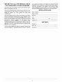
INSTALLATION DATA
Date Installed
Dealer Name
Address
City.
State
Telephone
Model No.
MFR. No.
Serial No.
Zip.
UNIT DATA
-
 1
1
-
 2
2
-
 3
3
-
 4
4
-
 5
5
-
 6
6
-
 7
7
-
 8
8


Ask a question and I''ll find the answer in the document
Finding information in a document is now easier with AI
Related papers
Other documents
-
Carrier 50ZPA User manual
-
Bryant 561G User manual
-
-
Reznor CSH1BE User manual
-
Reznor S6BQ User manual
-
 Bryant-Carrier PA4ZNA048000-TP Installation guide
-
-
-
 Payne PA10 Series User's Information Manual
-

