Page is loading ...

USER GUIDE & SERVICE MANUAL
1 Class
●
UHNB115 / UHNP115
●
15” Nugget Ice Machine

USER GUIDE & SERVICE MANUAL
u-line.com
Table of Contents
Intro
Safety
Safety and Warning
Disposal And Recycling
Installation
Environmental Requirements
Electrical
Cutout & Product Dimensions
Side by Side Installation
Water Hookup
Drain
Anti-Tip Bracket
General Installation
Integrated Panel Dimensions
Integrated Panel Installation
Grille Installation
Door Swing
Door Adjust
Maintenance
Cleaning
Cleaning Condenser
Extended Non-Use
Operating Instructions
Control Operation
Ice
Airflow and Product Loading
Service
Troubleshooting
Wire Diagram
Product Liability
Warranty Claims
Parts
Ordering Replacement Parts
R600a Specifications
System Diagnosis Guide
Compressor Specifications
Troubleshooting Extended
Control Operation - Service
Thermistor
Warranty

USER GUIDE
u-line.com
Introduction
WELCOME TO U-LINE
Congratulations on your U-Line purchase. Your product comes from a company with over ve decades of premium modular ice
making, refrigeration, and wine preservation experience. U-Line creates products focused on functionality, style, and inspired
innovations — paying close attention to even the smallest details. Applications include residential, outdoor, ADA height
compliant, marine, and commercial. Complete product categories include Beverage Centers, Wine Refrigerators, Ice Machines,
Refrigerators, Freezers, and Dispensers.
Our advanced refrigeration systems, large and exible capacities, and Built-In to Stand Out
®
clean integrated look allow you
to preserve the right product, in the right place, at the right temperature. Since 2014, U-Line has been part of the Middleby
family of brands. All products are designed, engineered, and assembled in Milwaukee, Wisconsin, USA, and select products
are available worldwide.
PRODUCT INFORMATION
Looking for additional information on your product? User Guides, Spec Sheets, CAD Drawings, Compliance Documentation,
and Product Warranty information are all available for reference and download at u-line.com.
PROPERTY DAMAGE / INJURY CONCERNS
In the unlikely event property damage or personal injury is suspected related to a U-Line product, please take the following
steps:
1. U-Line Customer Care must be contacted immediately at +1.414.354.0300.
2. Service or repairs performed on the unit without prior written approval from U-Line is not permitted. If the unit has been
altered or repaired in the eld without prior written approval from U-Line, claims will not be eligible.
GENERAL INQUIRIES
U-Line Corporation
8900 N. 55th Street
Milwaukee, Wisconsin 53223 USA
Monday - Friday 8:00 am to 4:30 pm CST
T: +1.414.354.0300
Email: sales@u-line.com
u-line.com
CONNECT WITH US
SERVICE & PARTS ASSISTANCE
Monday - Friday 8:00 am to 4:30 pm CST
T: +1.414.354.0300
Service Email: onlineservice@u-line.com
Parts Email: onlineparts@u-line.com
Designed, engineered and assembled in WI, USA
3

USER GUIDE
u-line.com
Safety and Warning
Safety and Warning
NOTICE
Please read all instructions before installing,
operating, or servicing the appliance.
Use this appliance for its intended purpose only and follow
these general precautions with those listed throughout this
guide:
SAFETY ALERT DEFINITIONS
Throughout this guide are safety items labeled with a
Danger, Warning, or Caution based on the risk type:
Danger means that failure to follow this safety
statement will result in severe personal injury or
death.
Warning means that failure to follow this safety
statement could result in serious personal injury
or death.
Caution means that failure to follow this safety
statement may result in minor or moderate
personal injury, property, or equipment damage.
This unit contains R600a (Isobutane) which is a
ammable hydrocarbon. It is safe for regular
use. Do not use sharp objects to expedite
defrosting. Do not service without consulting the
“R600a specications” section included in the
User Guide. Do not damage the refrigerant
circuit.
Service must be done by factory authorized
service personnel. Any parts shall be replaced
with like components. Failure to comply could
increase the risk of possible ignition due to
incorrect parts or improper service.
CALIFORNIA PROPOSITION 65
This product contains chemicals known to the
state of California to cause cancer and birth
defects or other reproductive harm.
www.P65warnings.CA.gov
This equipment is to be installed with adequate
backow protection to comply with applicable
federal, state and local codes.
DANGER
!
DANGER
!
WARNING
!
CAUTION
!
CAUTION
!
WARNING
!
4

USER GUIDE
u-line.com
Disposal and Recycling
Disposal and Recycling
RISK OF CHILD ENTRAPMENT. Before you throw
away your old refrigerator or freezer, take o
the doors and leave shelves in place so children
may not easily climb inside.
If the unit is being removed from service for disposal,
check and obey all federal, state, and local regulations
regarding the disposal and recycling of refrigeration
appliances, and follow these steps completely:
1. Remove all consumable contents from the unit.
2. Unplug the electrical cord from its socket.
3. Remove the door(s)/drawer(s).
DANGER
!
5

USER GUIDE
Environmental Requirements
u-line.com
Environmental Requirements
This model is intended for indoor/interior applications only
and is not to be used in installations that are open/
exposed to natural elements.
This unit is designed to operate between 50°F (10°C) and
100°F (38°C). Higher ambient temperatures may reduce
the unit’s ability to reach low temperatures and/or reduce
ice production on applicable models.
For best performance, keep the unit out of direct sunlight
and away from heat generating equipment.
In climates where high humidity and dew points are
present, condensation may appear on outside surfaces.
This is considered normal. The condensation will
evaporate when the humidity drops.
CAUTION
!
Damages caused by ambient temperatures of
40°F (4°C) or below are not covered by the
warranty.
6

USER GUIDE
Electrical
u-line.com
Electrical
WARNING
!
SHOCK HAZARD — Electrical Grounding
Required. Never attempt to repair or perform
maintenance on the unit until the electricity has
been disconnected.
Never remove the round grounding prong from
the plug and never use a two-prong grounding
adapter.
Altering, cutting or removing power cord,
removing power plug, or direct wiring can cause
serious injury, fire, loss of property and/or life,
and will void the warranty.
Never use an extension cord to connect power to
the unit.
Always keep your working area dry.
NOTICE
Electrical installation must observe all state and
local codes. This unit requires connection to a
grounded (three-prong), polarized receptacle
that has been placed by a qualified electrician.
The unit requires a grounded and polarized 115 VAC,
60 Hz, 15A power supply (normal household current). An
individual, properly grounded branch circuit or circuit
breaker is recommended. A GFCI (ground fault circuit
interrupter) is usually not required for fixed location
appliances and is not recommended for your unit because
it could be prone to nuisance tripping. However, be sure
to consult your local codes.
See CUTOUT & PRODUCT DIMENSIONS for recommended
receptacle location.
7

USER GUIDE
u-line.com
Cutout & Product Dimensions
Cutout & Product Dimensions
PREPARE SITE
Your U-Line product has been designed for either free-
standing or built-in installation. When built-in, your unit
does not require additional air space for top, sides, or
rear. However, the front grille must NOT be obstructed,
and clearance is required for an electrical connection in
the rear.
CAUTION
!
Unit can NOT be installed behind a closed cabinet
door.
If you would like to align the face of the unit with
other adjacent cabinet doors, you may need to
alter the wall just behind the drain connection on
the unit to accommodate the drain.
CUTOUT DIMENSIONS
PRODUCT DIMENSIONS
REAR
FRONT
TOP
SIDE
1 1⁄₂" (38 mm)
7"
(178 mm)
15"
(381 mm)
34 1⁄₄"
(870 mm)
to
35 1⁄₄"
(889 mm)
Preferred location
for electrical outlet
is in an adjacent
cabinet.
24"
(610 mm)
5⁄8"
(16 mm)
2”
(51 mm)
4”
(102 mm)
Drain
Water Line
7
½
”
(191 mm)
3
⁄
”
(80 mm)
4”
(102 mm)
7
½
”
(191 mm)
Power Cord
6 ft (183 cm)
14 ⁄”
(379 mm)
3 ½”
(89 mm)
28”
(711 mm)
33 ⁄”
to
34 ⁄”
(855 mm
to
881 mm)
1 ⁄”
(48 mm)
17 ½”
(445 mm)
21 ⁄”
(535 mm)
10 ⁄”
(260 mm)
22 ⁄”
(583 mm)
24 ⁄”
(630 mm)
4
⁄
“ (111 mm)
*
*
*Add 1⁄2” for integrated models with 3⁄4” panel installed.
8

USER GUIDE
Side-by-Side Installation
u-line.com
Side-by-Side Installation
OTHER SITE REQUIREMENTS
Side-by-Side Installation
Units must operate from separate, properly grounded
electrical receptacles placed according to each unit’s
electrical specifications requirements.
Cutout width for a side-by-side installation is the total of
the widths listed under Cutout Dimensions in each unit’s
Installation Guide. Each door can be opened individually
(one at a time) without interference.
However, to ensure unobstructed door swing (opening
both doors at the same time), 1/4" (6.4 mm) of space
needs to be maintained between the units.
Hinge-by-Hinge Installation (Mullion)
When installing two units hinge-by-hinge, 13/16" (22 mm)
is required for integrated models. Additional space may be
needed for any knobs, pulls or handles installed.
Stainless steel models which include the standard stainless
handle will require 4-9/16" (116 mm) to allow both doors
to open to 90° at the same time.
1/4" (6 mm)
13/16" (22 mm)
4-9/16" (116 mm)
9

USER GUIDE
u-line.com
Water Hookup
Water Hookup
PREPARE PLUMBING
The water valve uses a standard 1/4” (6.35 mm)
compression tting. U-Line recommends using accessory
water hook up kit – part # 80-54674-00. The kit includes
a 10’ (3 m) braided exible water supply line and a brass
hose tting.
Plumbing installation must observe all state
and local codes. All water and drain connections
MUST BE made by a licensed/qualied plumbing
contractor. Failure to follow recommendations
and instructions may result in damage and/or
harm.
Water Supply Connection
When connecting the water supply, please note the
following:
• Before installing the unit and connecting to the cold
water supply, review the local plumbing codes.
• The water pressure should be between 20 and 120 psi
(138 and 827 kPa).
• TDS (Total Dissolved Solids) between 5 ppm (mg/L)
and 400 ppm (mg/L) and water hardness less than 200
mg/L (ppm), 12 gpg (grains per gallon).
• TDS and/or water hardness above these limits should
be treated with a reverse osmosis system or other
ltration system.
• Softened water is not recommended as it may result in
softer ice than desired.
• The water line MUST have a shut-o valve in the
supply line.
• The water line should be looped into 2 coils. This
will allow the unit to be removed for cleaning and
servicing. Make certain that the tubing is not pinched
or damaged during installation.
Do not use any plastic water supply line. The line
is under pressure at all times. Plastic may crack
or rupture with age and cause damage to your
home.
Do not use tape or joint compound when
attaching a braided exible water supply line
that includes a rubber gasket. The gasket
provides an adequate seal – other materials
could cause blockage of the valve.
Failure to follow recommendations and
instructions may result in damage and/or harm,
ooding or void the product warranty.
Use new hose set. Do not reuse old hose set.
Turn o water supply and disconnect electrical
supply to unit prior to installation.
Use caution when handling back panel. The edges
could be sharp.
CAUTION
!
CAUTION
!
CAUTION
!
10

USER GUIDE
u-line.com
Water Hookup
1. Turn o water supply and disconnect electrical supply
to product prior to attempting installation.
2. Remove the back panel.
3. Thread water line through back panel hole (with
bushing).
4. Locate water valve inlet and connect to valve.
5. Turn on water supply and check for leaks.
6. Reinstall back panel.
3
4
11

USER GUIDE
u-line.com
Drain
If your U-Line unit did not come with a factory
installed drain pump you must use a gravity
style drain connection. For assistance in
determining if your unit has a pump please
contact U-Line. The oor drain must be large
enough to accommodate drainage from all
attached drains. Follow these guidelines when
installing drain lines to prevent water from
owing back into the ice maker storage bin and/
or potentially owing onto the oor, which may
result in personal injury or property damage
Failure to connect water supply or drain line
connections properly can result in personal injury
and property damage. Gravity drain connections
must be routed downward from the rest of the
unit at the rate of 1/4” per foot (1 cm per 50 cm).
Drain can NOT be located directly below the
unit. Unit has a solid base that will not allow the
unit to drain below itself.
There is a possibility that hose connections may
have loosened during shipment.
Verify all connections and ttings are free from
leaks.
This equipment is to be installed with adequate
backow protection to comply with applicable
federal, state and local codes
Model numbers including “CL” or “NB” do not include a
factory installed drain pump.
Model numbers including “CP” or “NP” include a factory
installed drain pump.
A gravity drain may be used if:
Drain line has at least a 1” drop per 48” (approximately
2 cm drop per 100 cm) of run.
Drain line does not create traps and is vented per local
code.
1. Cut the pre-installed drain tube to length.
2. Connect to your local plumbing per the local code.
3. If necessary, insulate drain line to prevent
condensation.
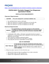
DRAIN CONNECTION
GRAVITY DRAIN
NOTICE
Drain
CAUTION
!
CAUTION
!
CAUTION
!
Normal
Proper Drain
With Trap
Poor Drainage, Water Will Back Up
With Trap and Vent
Proper Drain
12

USER GUIDE
u-line.com
Drain
The maximum lift for the P60 drain pump is
10 feet. This must be done as close to the rear of
the unit as possible.
If your drain line will run up to a stand pipe, disposal
or spigot assembly, or does not otherwise meet the
requirements for a gravity drain, you may have ordered a
pre-installed U-Line P60 drain pump.
If you need to install a P60 drain pump into your unit, see
DRAIN PUMP section in the User Manual.
See below for typical installations requiring a drain pump.
FACTORY INSTALLED DRAIN PUMP
NOTICE
Cold
Water
Hot
Water
Waste
Waste
Shut-Off
Valve
Stand Pipe
P60 Pump Required
Air Gap
(Optional Hook-Up)
Cold
Water
Hot
Water
Waste
Shut-Off
Valve
Disposal Assembly
P60 Pump Required
Waste
Cold
Water
Shut-Off
Valve
Hot
Water
Air Gap
(Optional Hook-Up)
Y-Branch Tailpiece
P60 Pump Required
13

USER GUIDE
u-line.com
Anti-Tip Bracket
Anti-Tip Bracket
Use one of the methods below to secure the unit
CABINET/COUNTER ANTI-TIP INSTALLATION
(For built-in applications)
1. Slide unit out so screws on front of unit are easily
accessible.
2. Remove the two screws from the front of the unit.
3. Bend bracket along one of the perforations to allow
attachment to the desired adjoining surface.
4. Gently push unit into position. Be careful not to
entangle the electrical cord or water line, if applicable.
5. Check to be sure the unit is level from front to back
and side to side. Make any necessary adjustments.
The unit’s top surface should be approximately ”
(3 mm) below the countertop.
6. Secure bracket to adjoining surface.
FLOOR MOUNTED ANTI-TIP INSTALLATION
(For free-standing applications)
1. Locate two anti-tip brackets included with the kit.
2. Place the unit into the area where it will be installed.
test to make sure the door opens and closes freely.
3.
center of the unit.
4. Remove the unit. Using a square, extend center line
“B” (see chart below). This line serves as the back
edge for the anti-tip brackets. From the center line,
edge of each bracket.
C
L
Back wall
Back of unit
Front of unit
Surrounding
area (Top view)
A
A
B
515 518 524
A 7 9” 11 ”
B 22” 22” 22”
5.
drawn for the outer edge. Mark spots for the screw
holes.
C
L
Surrounding
area (Top view)
Drill holes and
mount anti-tip
brackets to floor
Back wall
Front
of
unit
Back
of
unit
A
A
B
6. Use a 1/8” drill to make two starter holes and fasten
provided.
7. Place the unit back into position, making sure the
feet engage the anti-tip brackets properly. Check
3 with the position of the front feet to ensure proper
positioning.
14

USER GUIDE
u-line.com
General Installation
General Installation
LEVELING INFORMATION
1. Use a level to
conrm the unit is
level. Level should
be placed along top
edge and side edge
as shown.
2. If the unit is not level, adjust the legs on the corners of
the unit as necessary.
3. Conrm the unit is level after each adjustment and
repeat the previous steps as needed.
INSTALLATION TIP
If the room oor is higher than the oor in the cutout
opening, adjust the rear legs to achieve a total unit rear
height of
1⁄8” (3 mm) less than opening’s rear height.
Shorten the unit height in the front by adjusting the front
legs. This allows the unit to be gently tipped into the
opening. Readjust the front legs to level the unit after it is
correctly positioned in the opening.
INSTALLATION
1. Plug in the power/electrical cord.
2. Gently push the unit into position. Be careful not
to entangle the cord or water and drain lines, if
applicable.
3. Re-check the leveling, from front to back and side to
side. Make any necessary adjustments. The unit’s top
surface should be approximately
1⁄8” (3 mm) below
the countertop.
4. Install the anti-tip bracket.
5. Remove interior packing material and wipe out the
inside of the unit with a clean, water-dampened cloth.
1
Turn to Adjust
15

USER GUIDE
Integrated Panel Dimensions
u-line.com
Integrated Panel Dimensions
Metric measurements rounded and optimized.
INTEGRATED PANEL
NOTICE
Due to differences in surrounding cabinetry the
panel may not perfectly align with door. The
procedure below is designed to provide a
finished integrated panel that seamlessly
integrates with surrounding cabinetry.
Panel Preparation
A full integrated door panel completely covers the door
frame and provides a built-in appearance.
NOTICE
The door panel must not weigh more than 20 lbs
(10 kg).
It is important to ensure that all drilled holes are
drilled to the correct depth in order to avoid
splits in the wood when hardware is installed.
1. Cut the panels to the dimensions listed in the diagram
below.
2. Optional: Stain or finish panel to desired stain or color.
Be sure to closely follow the instructions provided by
the manufacturer.
3. Optional: Install handles and hardware.
NOTICE
When applying an integrated panel to a unit,
ensure that both sides are finished in order to
prevent warping. In some panel installations,
the panel may be visible through the glass while
the door is open.
Integrated Panel Dimensions
BACK SURFACE MUST HAVE AMPLE FLAT SURFACE
TO MOUNT OVERLAY PANEL FLAT AND WITHOUT
INTERFERENCE
Ώȟȯ"
(20 mm)
Integrated Panel
14-ΑȟȬȱ"
(379 mm)
30"
(762 mm)
16

USER GUIDE
Integrated Panel Dimensions
u-line.com
HANDLELESS INTEGRATED DOOR PANEL
The following procedure is designed to provide a finished,
handleless solid panel for an 15" (381 mm) door that
seamlessly integrates with its surrounding cabinetry.
NOTE: Many cabinet manufacturers provide a ready
solution for a handleless, integrated design that can be
easily applied to your model. Consult your cabinet
manufacturer for applicable design and installation details.
The cabinet manufacturer’s solution to this design and
integration detail will often result in an integrated panel
solution wherein the size of the panel may result in a
height dimension taller than what we specify. This can be
achieved provided the additional height is positioned
above the appliance door.
NOTICE
The integrated panel aligns with the surrounding
cabinetry and, due to differences in cabinetry,
may not align perfectly with the door.
The appliance will need up to 34-1/2" (876 mm)
to the underside of the counter to leave room for
leveling adjustments.
A single prepared panel with insert must not
weigh more than 20 lbs (10 kg).
Integrated Panel Preparation
1. Cut the main panel to the dimensions below. For
details, see the drawings on the next page.
2. Create the top design for the handleless feature and
the 1/8" (3 mm) notch for the insert(s) indicated on
the Top Detail drawing, on the next page.
3. Prepare the insert(s) that will back up the handleless
design. Wooden Insert – Cut 1/8" (3 mm) thick
wooden insert(s) to the dimensions below.
4. Optional: Stain or finish panel and wooden insert to
desired stain or color. Be sure to closely follow the
instructions provided by the manufacturer.
NOTICE
If finishing panel or wooden insert, all sides
must be finished to prevent warping.
5. Attach the insert to the panel. Wood glue or equivalent
adhesive should be used to attach insert to panel.
Main panel width Main panel height
14-15/16" (379 mm) 28-13/16" (732 mm)
Wooden insert width Wooden insert height
14-15/16" (379 mm) 3-1/2" (89 mm)
Top Design
and Insert Notch
Wooden Insert
Main Panel
Integrated Panel
Attach Wooden Insert
17

USER GUIDE
Integrated Panel Dimensions
u-line.com
Handleless Integrated Panel Dimensions
ΏȟΚ" (20 mm)
28-
ΏȟΗΜ"
(732 mm)
2-
Ώȟȯ"
(70 mm)
2-
Ώȟȯ"
(70 mm)
R
ΑȟΞ"
(R 16 mm)
ȟΞ" (3 mm)
ȟΚ" (6 mm)
Wooden Insert
Notch Depth:
/Ξ" (3 mm)
2-
ΏȟΞ"
(60 mm)
ΓȟΞ" (22 mm)
Ref.
Top Detail
Insert Notch
Top Design
ȟΞ" (3 mm)
3-
ȟΘ"
(89 mm)
14-
ΑȟΗȱ" (379 mm)
Wooden Insert Dimensions
14-ΑȟΗȱ"
(379 mm)
18

USER GUIDE
Integrated Panel Dimensions
u-line.com
3-5/16" (89 mm)
to
4-5/16" (114 mm)
U-Line
Unit
U-Line
Unit
Integrated Panel
Integrated Panel/Integrated Frame
Front Side
Front Side
3-5/16" (89 mm)
to
4-5/16" (114 mm)
Floor
Cabinet
> 3-5/16"
(> 89 mm)
3-5/16" (89 mm)
to
1" (25 mm)**
U-Line
Unit
Extended Integrated Panel/Extended Integrated Frame
Floor
Cabinet
3-5/16" (89 mm)
to
1" (25 mm)**
*
U-Line
Unit
Integrated Panel
3. Optional: Install handles and hardware
NOTICE
The door panel must not weigh more than 20 lbs
(10 kg).
It is important to ensure that all drilled holes are
drilled to the correct depth in order to avoid
splits in the wood when hardware is installed.
Appliance will need up to 34-1/2" (876 mm) to
the underside of the counter to leave room for
leveling adjustments.
When applying an integrated panel to a unit,
ensure that both sides are finished in order to
prevent warping. In some installations, the panel
may be visible through the glass while the door is
open.
EXTENDED INTEGRATED PANEL
NOTICE
Due to differences in surrounding cabinetry the
panel may not perfectly align with door. The
procedure below is designed to provide a
finished panel that seamlessly integrates with
surrounding cabinetry.
Panel Preparation
An extended integrated panel can be used to maintain
alignment with an adjacent extended cabinet height or a
reduced toe-kick/grille application.
1. Cut the panels to the dimensions listed in the
appropriate diagram on the next page.
2. Optional: Stain or finish panel to desired stain or color.
Be sure to closely follow the instructions provided by
the manufacturer.
* Panel can extend beyond the door frame.
** A minimum of 1" (25 mm) from the floor
is required for proper ventilation.
19

USER GUIDE
Integrated Panel Dimensions
u-line.com
Extended Integrated Panel Dimensions Integrated Grille
If you would like to cover the grille with an integrated
panel, purchase U-Line’s adjustable grille accessories.
15” - Sales Accessory: ULAGRILLE15
Complete instructions, including dimensions of the
integrated grille panel, are included with the accessory.
* A minimum of 1" (25 mm) is required from the
floor to the bottom of the extended integrated
panel/frame for proper ventilation.
BACK SURFACE MUST HAVE AMPLE FLAT SURFACE
TO MOUNT OVERLAY PANEL FLAT AND WITHOUT
INTERFERENCE
Ώȟȯ"
(20 mm)
Integrated Panel
14-ΑȟȬȱ"
(379 mm)
30"
(762 mm)
20
/