
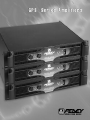
GPS Series Amplifiers
™
GPS Series Amplifiers
™
O P E R A T I N G G U I D E

2
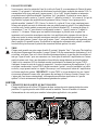
Intended to alert the user to the presence of uninsulated “dangerous voltage” within the product’s
enclosure that may be of sufficient magnitude to constitute a risk of electric shock to persons.
Intended to alert the user of the presence of important operating and maintenance (servicing)
instructions in the literature accompanying the product.
CAUTION: Risk of electrical shock — DO NOT OPEN!
CAUTION: To reduce the risk of electric shock, do not remove cover. No user serviceable parts inside. Refer
servicing to qualified service personnel.
WARNING: To prevent electrical shock or fire hazard, do not expose this appliance to rain or moisture. Before
using this appliance, read the operating guide for further warnings.
Este símbolo tiene el propósito, de alertar al usuario de la presencia de “(voltaje) peligroso” sin ais-
lamiento dentro de la caja del producto y que puede tener una magnitud suficiente como para constituir
riesgo de descarga eléctrica.
Este símbolo tiene el propósito de alertar al usario de la presencia de instruccones importantes sobre la
operación y mantenimiento en la información que viene con el producto.
PRECAUCION: Riesgo de descarga eléctrica ¡NO ABRIR!
PRECAUCION: Para disminuír el riesgo de descarga eléctrica, no abra la cubierta. No hay piezas útiles dentro.
Deje todo mantenimiento en manos del personal técnico cualificado.
ADVERTENCIA: Para evitar descargas eléctricas o peligro de incendio, no deje expuesto a la lluvia o humedad
este aparato Antes de usar este aparato, Iea más advertencias en la guía de operación.
Ce symbole est utilisé dans ce manuel pour indiquer à l’utilisateur la présence d’une tension dangereuse
pouvant être d’amplitude suffisante pour constituer un risque de choc électrique.
Ce symbole est utilisé dans ce manuel pour indiquer à l’utilisateur qu’il ou qu’elle trouvera d’importantes
instructions concernant l’utilisation et l’entretien de l’appareil dans le paragraphe signalé.
ATTENTION: Risques de choc électrique — NE PAS OUVRIR!
ATTENTION: Afin de réduire le risque de choc électrique, ne pas enlever le couvercle. Il ne se trouve à l’intérieur
aucune pièce pouvant être reparée par l’utilisateur. Confiez I’entretien et la réparation de l’appareil à un réparateur
Peavey agréé.
AVERTISSEMENT: Afin de prévenir les risques de décharge électrique ou de feu, n’exposez pas cet appareil à la
pluie ou à l’humidité. Avant d’utiliser cet appareil, lisez attentivement les avertissements supplémentaires de ce
manuel.
Dieses Symbol soll den Anwender vor unisolierten gefährlichen Spannungen innerhalb des Gehäuses
warnen, die von Ausreichender Stärke sind, um einen elektrischen Schlag verursachen zu können.
Dieses Symbol soll den Benutzer auf wichtige Instruktionen in der Bedienungsanleitung aufmerksam
machen, die Handhabung und Wartung des Produkts betreffen.
VORSICHT: Risiko — Elektrischer Schlag! Nicht öffnen!
VORSICHT: Um das Risiko eines elektrischen Schlages zu vermeiden, nicht die Abdeckung enfernen. Es befinden
sich keine Teile darin, die vom Anwender repariert werden könnten. Reparaturen nur von qualifiziertem
Fachpersonal durchführen lassen.
ACHTUNG: Um einen elektrischen Schlag oder Feuergefahr zu vermeiden, sollte dieses Gerät nicht dem Regen
oder Feuchtigkeit ausgesetzt werden. Vor Inbetriebnahme unbedingt die Bedienungsanleitung lesen.

GPS
™
SERIES
POWER AMPLIFIERS
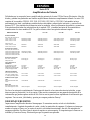
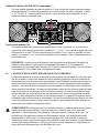
Congratulations on your purchase of the new GPS Series amplifier by Peavey Electronics. Years of power amp
design and testing have produced a totally refined, dynamic power amp product line. The GPS Series consists
of the GPS 900, GPS 1500, GPS 2600, GPS 3400 and GPS 3500. Each model features tunnel cooling, two
variable-speed fans, initialization protection and DDT
™
speaker protection. There are, however, differences
between the various models such as output power and connections. This guide will describe each feature of
your GPS Series amplifier and note the features common to specific models. The chart below offers a quick
reference.
3
ENGLISH
GPS
™
Series Power Amps
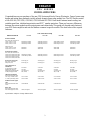
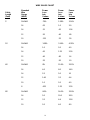
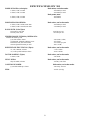
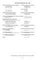
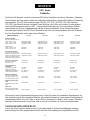
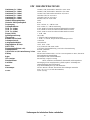
SPECIFICATIONS
OUTPUT POWER
Stereo mode, both channels driven
2 ohms, 1 kHz, 0.1% THD
4 ohms, 1 kHz, 0.1% THD
8 ohms, 1 kHz, 0.1% THD
Bridge mode, mono
4 ohms, 1 kHz, 0.1% THD
8 ohms 1 kHz, 0.1% THD
RATED OUTPUT POWER:
Stereo mode, both channels driven
4 ohms, 20 Hz to 20 kHz, 0.03% THD
8 ohms, 20 Hz to 20 kHz, 0.02% THD
4 ohms, 20 Hz to 20 kHz, 0.1% THD
8 ohms, 20 Hz to 20 kHz, 0.08% THD
SLEW RATE:(Typical value)
Stereo mode, each channel
Bridge mode, mono
INPUT SENSITIVITY &
IMPEDANCE:
@ rated output power, 4 ohms
unbalanced, 1/4" phone jack
Balanced, XLR (polarity selectable)
Overall system gain per channel
FREQUENCY RESPONSE:
Stereo mode, both channels driven
+0m -1 dB @ 1 WRMS, 4 ohms
+0, -0.2 dB @ rated output, 4 ohms
DAMPING FACTOR: (Typical
value)
Stereo mode, both channels driven
8 ohms
Hum & Noise:
Stereo mode, both channels driven
Below rated output power, 4 ohms
GPS
™
900
450W RMS per channel
330W RMS per channel
200W RMS per channel
900W RMS
660W RMS
300W RMS per channel
1700W RMS per channel
40 Volts per µsec
80 Volts per µsec
0.87V RMS
20 k ohms
10 k ohms per leg
40X (+32 dB)
5 Hz to 50 kHz
20 Hz to 20 kHz
Greater than 400
100 dB, unweighted
GPS
™
1500
750W RMS per channel
550W RMS per channel
320W RMS per channel
1500W RMS
1100W RMS
500W RMS per channel
280W RMS per channel
40 Volts per µsec
80 Volts per µsec
1.12V RMS
20 k ohms
10 k ohms per leg
40X (+32 dB)
5 Hz to 50 kHz
20 Hz to 20 kHz
Greater than 400
100 dB, unweighted
GPS
™
2600
1300W RMS per channel
950W RMS per channel
620W RMS per channel
2600W RMS
1900W RMS
900W RMS per channel
600W RMS per channel
40 Volts per µsec
80 Volts per µsec
1.54V RMS
20 k ohms
10 k ohms per leg
40X (-32 dB)
5 Hz to 100 kHz
10 Hz to 30 kHz
Greater than 700
100 dB, unweighted
GPS
™
3500
1700W RMS per channel
1200W RMS per channel
775W RMS per channel
3500W RMS
2400W RMS
1050W RMS per channel
750W RMS per channel
40 Volts per µsec
80 Volts per µsec
1.62V RMS
20 k ohms
10 k ohms per leg
40X (+32 dB)
5 Hz to 100 kHz
10 Hz to 30 kHz
Greater than 325
100 dB, unweighted
Specifications subject to change without notice.

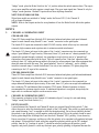
Please read this guide in its entirety. Pay close attention to the various warnings within as they pertain to the
safety of you and your product. Each section will begin with a short description of the information you can
expect to obtain within. This should help you to locate the material you are looking for in a timely manner.
Once again, congratulations and thank you for buying Peavey!
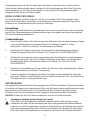
UNPACKING/REGISTRATION
Inspect the amplifier during unpacking. If you find any damage, notify your dealer immediately. Be sure to
save the carton and all packing materials. Should you ever need to ship the unit back to Peavey Electronics,
one of its service centers, or the dealer, use only the original factory packing. Please fill out your registration
card at this time. It is important that you complete the entire form and mail it to Peavey Electronics in order
for your warranty to apply.
INSTALLATION AND MOUNTING
GPS Series amplifiers are 2-rack-space units that mount in a standard 19-inch rack. On all amplifiers, four
front panel mounting holes are provided. Refer to the specifications for your specific model in this manual.
QUICK START
The following section lists the steps for basic usage. This is only a quick reference. It is very important that
you read the entire manual in order to ensure the safe and optimum operation of your GPS Series amplifier.
TO SET UP THE AMPLIFIER FOR BASIC USAGE:
1. Rack mount the amplifier in the location where it is to be used, remembering to allow for adequate
access and cooling space. For more information, see the section on Cooling Requirements.
2. Make input connections, balanced or unbalanced, to the combination input connector on the rear panel.
See the sections on The INs and OUTs of MODE SELECTION for more information.
3. Connect speakers to the output jacks or binding posts. Be sure to make the correct output connections
for stereo or bridged mono configuration. See the section on The INs and OUTs of MODE
SELECTION for more information.
4. Make power connections, allowing for proper current draw. See the section on AC Mains Circuit Size
Requirements for more information.
5. Turn down (fully counterclockwise) the two gain attenuators on the front panel. Turn the front panel
AC switch to “ON,” and bring up the gain attenuators to the desired levels.
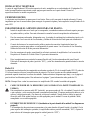
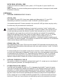
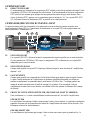
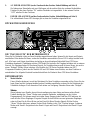
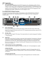
AC POWER
The following section will describe the AC power features of your GPS Series amplifier. AC power is a
critical element in power amplification. Please read this section carefully, paying special attention to any
warning signs. Refer to the diagram below and on page 8 to locate these features. Refer to page 7 for operation
notes regarding AC power.
NOTE: Always make connections to your GPS Series amplifier while the unit is turned off.
1. REMOVABLE AC POWER CORD (Located on the rear of the unit)
This receptacle is for the IEC line cord (included), which provides AC power to the unit. Connect the
line cord to this connector and to a properly grounded AC supply. Damage to the equipment may occur
if an improper line voltage is used. (See voltage marking on unit.) Never remove or cut the ground pin
of the line cord plug. This unit is supplied with a properly rated line cord. When lost or damaged,
replace this cord with one of the proper ratings.
4

2. AC POWER SWITCH (Located on the front of the unit. See diagram on page 9.)
A two-position power switch is on the right side of the front panel. With the top portion of the switch
pushed to the “IN” position the amplifier is “ON”. Press the bottom portion of the switch to the
“IN” position to turn the unit “OFF”.
3. POWER LED (Located on the front of the unit. See diagram on page 9.)
The Power LEDs illuminate to indicate the amplifier is turned on.
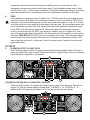
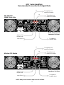
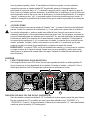
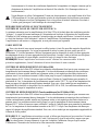
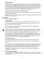
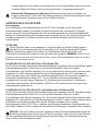
REAR PANEL
THE INS AND OUTS OF MODE
SELECTION
Once you have provided proper AC power to the amplifier, you may now connect to the inputs and outputs.
Remember to do this while the power to the unit is turned off (Power LED are not lit). The rear panel of your
GPS Series amplifier provides a central location for all input and output connections. Regardless of the GPS
model, all input connections are located at the bottom-center portion of the rear panel and all output
connections are located at the top-center portion. In addition, your amplifier can operate in either stereo or
bridged (mono) mode. All GPS Series amplifiers have DDT compression. However, only GPS models 900 and
1500 have a switch to defeat this feature. This section will describe these areas of your GPS Series amplifier in
detail.
MODE SELECTION
4. MODE SWITCH
This switch determines which mode your amplifier will operate in. Before connecting your input signal
and speaker cables to the amp, you must determine how you want the amp to function. Two modes of
operation are offered on your amplifier, stereo or bridged (seperate).
STEREO:
When we use the term “stereo” we are referring to two channels, not necessarily left and right.
Therefore, in “stereo” mode there are essentially two power amps regardless of input type. You may
use a stereo input, one stereo input to each channel of the GPS, or you may send two mono inputs to
the GPS in the same manner. A good example of two separate inputs would be the use of one channel
for mono mains and one channel for mono monitor signals. In order to select the “stereo” mode of
operation you must place the Mode Switch in the “out” position. In this mode, Channel A Output is
supplied by the Channel A Input. Channel B Output is supplied by Channel B Input.
BRIDGED OR MONO:
In the “bridge” mode the two channels of the amplifier combine to form a single mono channel. The
benefit of using your amplifier in this mode is that the power is doubled. Refer to the specifications in
this manual for detailed output power specs on your specific model. To use the GPS Series amp in
5
6 7 5
4
1
8

“bridge” mode, place the Mode Switch to the “in” position where the switch remains down. The amp is
now a mono amplifier and only requires a single input. Plug your input signal into Channel A only for
“bridge” mode operation. Channel B input must not have anything connected.
NOTE FOR GPS 900 AND 1500:
When these models are switched to “bridge” mode, the Power LED (3) for Channel B
will no longer illuminate.
NOTE: Refer to the Outputs section for an explanation of how the Mode Switch affects the speaker
outputs.
INPUTS
5. CHANNELA COMBINATION INPUT
GPS 900 AND 1500
These GPS Series amplifiers offer both XLR electronic balanced and phone jack quasi-balanced
inputs for each channel using Neutrik
®
’s new “combo” connector to save panel space.
The female XLR inputs are connected to dual OP AMP circuitry which offers very low noise and
extremely high common mode rejection ratio to minimize outside interference!
The female 1/4" phone jack input in the center of the “combo” connectors are also connected to a
unique “quasi-balanced” input circuitry. When used, these 1/4" jacks are not “chassis grounded” but
connected to ground through a relatively low impedance circuit which is part of a "ground loop"
elimination circuit associated with the input. This will normally allow "hum free" operation when
relatively short 1/4" cable patches are made to this input by various outputs from other equipment that
share the same rack with this amp. This “quasi-balanced” circuit is “automatic”, and is virtually
invisible in normal usage. It cannot be defeated. Use only a two-conductor (TS) phone plug when
connecting to the 1/4" input of this connector.
GPS 2600, 3400 AND 3500
These GPS Series amplifiers offer both XLR electronic balanced and phone jack balanced/unbalanced
inputs for each channel using Neutrik's new “combo” connector to save panel space.
The female 1/4" phone jack input in the center of the “combo” connectors is also connected to a
unique balanced/unbalanced input circuitry. When used, these 1/4" jacks can accept both unbalanced
two-conductor (TS) and balanced three-conductor (TRS) inputs. Balanced operation is always
recommended for optimum signal-to-noise. If unbalanced operation is a required, always keep the
input cable to a minimum length to avoid excessive noise.
6. CHANNEL B COMBINATION INPUT
This connector is identical to the Channel A Combination Input (5) except it is not used during
“bridge” mode [See Mode Switch (4).]
7. INPUT POLARITY
Located between the Channel A and Channel B Inputs is a recessed Input Polarity switch (7) that
allows the user to select the desired polarity (phase) of the XLR inputs. This switch is a push-push type
and a small diameter “tool” is required to select the desired position. Set to the out (default) position,
the polarity is pin #3 positive, pin #2 negative, and pin #1 ground. This is the polarity found on most
Peavey power amplifiers. Although this is not the world “standard” (IEC) polarity, it was chosen by
Peavey more than 20 years ago, and thus we offer this polarity to be consistent with products both past
and present. If this amplifier is used with other competitive products which use the IEC standard
polarity, then the “in” position of switch (7) should be selected yielding pin #2 positive, pin #3
negative, and pin #1 ground. As with any electronic gear, polarity (phasing) is important because the
6

loudspeaker enclosures associated with this power amplifier must be in phase with any other
loudspeaker enclosures associated with other power amps. If one loudspeaker system were to “push”
while the other “pulls”, a serious sound “cancellation” could result. Changing the setting of the polarity
switch has the same effect as reversing the polarity of the loudspeaker connections at the output.
8. THRU
Each channel has a female phone jack (8) labeled “thru”. This Thru jack offers very flexible patching
capability. When the XLR input of the combination connectors (5 and 6) are used, this THRU jack is
the output of the electronic balanced input circuitry, and as such can be used as a “line out” to connect
to the other input jack on this amplifier or other amps in the same rack. Thus, one balanced mixer feed
can be connected to the amp via the XLR connector and then further distributed (unbalanced) locally
via the THRU jack. Alternatively, when the 1/4" phone jack input of the combination connectors
(5 and 6) is used as the input, the THRU jack becomes a “bridged” input to it (similar to a Y-cord),
again allowing this input signal to be patched to the other input jack on this amplifier or other amps in
the system. IMPORTANT: The THRU jack is not intended to be an “input”, and inadvertent usage as
such will result in excessive loading of the input source. Although not a catastrophic mistake, it will
cause a significant reduction in “system gain” due to the loading, and will seriously limit the overall
system performance.
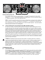
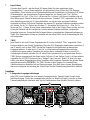
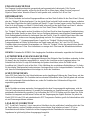
OUTPUTS
9. SPEAKER OUTPUT CONNECTORS
Each GPS Series amplifier offers two separate output sections featuring parallel outputs. The type of
output jack differs from model to model. Find the model and AC supply voltage of your unit to identify
which description is applicable to your product.
GPS 900 OR GPS 1500 120 VAC (DOMESTIC) MODELS:
These two models feature 1/4" output jacks located on the top-center of the rear panel. There are two
parallel 1/4" jacks per channel which are labeled either “CHANNEL A” or “CHANNEL B”. In
addition to the 1/4" output jacks, Binding Posts (10) are also provided for each channel.
7
9
10
11
10
9

All other GPS models:
These models offer dual Speakon
®
Quick Connectors. The Speakon
®
is a four-wire connector with the
connections labeled as 1+, 1-, 2+ and 2-. The Speakon connectors found on your GPS Series amplifier
are connected with pins 1+ and 2+ wired in parallel to the positive output. Pins 1- and 2- are wired in
parallel to the negative output. This is typical for each channel.
NOTE: Consult your loud speaker specifications to determine the wiring configuration that will best
suit your system. The diagrams on pages 13 and 14 display the recommended hookup for your GPS
Series amplifier. In addition to the Speakon
®
Quick Connectors, Binding Posts (10) are also provided
for each channel.
10. BINDING POST OUTPUT CONNECTORS
Five-way binding post speaker outputs can be found on each channel regardless of model. For each
channel, the outputs are in parallel, hence the speaker connection cables can be terminated with banana
plugs or stripped wires for use in the binding post terminals as well as the output connectors (9). For
sustained high power applications, the use of the binding post terminals is recommended; however,
care must be exercised to assure the correct speaker polarity. The red binding posts are the signal
outputs from each channel, and the black binding posts are chassis ground. The red binding post should
be connected to the positive inputs of the associated loudspeakers. For “bridge” mode operation, only
the red binding posts are used, and the associated loudspeaker load is connected between the two red
binding posts. The red binding post associated with Channel A should be considered the positive output
for the system and thus should be connected to the positive input of the associated loudspeaker system.
WARNING: Regardless of what connections are used, the minimum parallel speaker load should
always be limited to 2 ohms per channel or 4 ohms “bridge” mode for any application. Operation at
loads of 4 ohms per channel or 8 ohms “bridge” mode is more desirable for sustained operation
applications due to the fact that the amplifier will run much cooler at this loading. Operation above 4
ohms per channel and even open circuit conditions can always be considered safe; however, sustained
operation at loads below 2 ohms could result in temporary amplifier shut down due to the thermal
limits fault circuitry.
DDT COMPRESSION
11. DDT DEFEAT
This switch is used to defeat the DDT compression used to protect against signal clipping. Only the
GPS 900 and 1500 models offer this feature. It is recommended to leave the DDT compression
enabled at all times to protect your speakers from damaging square waves. The DDT function is
disabled when the switch is pressed to the “in” position. The DDT LEDs (12) will illuminate when
DDT compression is occurring in that particular channel.
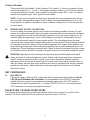
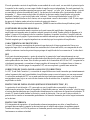
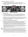
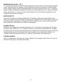
FRONT PANEL CONTROLS/INDICATORS
The following section describes the controls and indicators found on the front panel of your GPS Series
amplifier. The Power Switch and LED are explained in a previous section, AC Power.
8

12. DDT LEDs
The DDT LEDs will illuminate when signal compression is occurring in that channel. If you have a
GPS 900 or 1500 and you have the DDT compression defeated, these LED will indicate the channel
is clipping.
13. SIGNAL LEDs
Each channel has a Signal LED, which comes on when the amplifier channel output exceeds 1 volt.
14. INPUT GAIN
Each channel has an Input Gain control used to adjust the gain of the input signal. Maximum power
amplifier input gain (minimum sensitivity) is achieved at the full clockwise setting (30 dB or 40x).
This setting yields maximum mixer/system headroom. A setting of less than full clockwise will yield
lower system noise at the expense of headroom.
15. FAN GRILL (located on front and rear panel)
Two continuously variable-speed DC fans supply cool air to the amplifier.
GPS 900 AND 1500
The fans operate at a quiet, low speed when the unit is turned on. The speed of the fans increase as the
amplifier heatsinks require cooling. (See Operation Notes.)
GPS 2600, 3400 AND 3500
The fans do not operate when the unit is first turned on. The operation and speed of the fans are
temperature dependent and change as the amplifier heatsinks require cooling. (See Operation Notes.)
DO NOT BLOCK THIS EXHAUST PORT! During the operation of your GPS Series amplifier, it
will require fresh air intake in order for the tunnel cooling to function properly. Blocking this air
exhaust port or the air intake ports on the rear could result in thermal shutdown of your amplifier.
OPERATION NOTES
AC MAINS CIRCUIT SIZE REQUIREMENTS.
Power requirements for the GPS Series amplifiers are rated at “typical” music conditions. The maximum
power current draw rating is limited by the amplifier’s circuit breaker. Consult the specification sheet for the
current that each amplifier will demand. AC mains voltage must be the same as that indicated on the back of
the amplifier. Damage caused by connecting the amplifier to improper AC voltage is not covered by any
warranty.
9
12
15
2
14
14
15
13 3

LINE CORD
For your safety, we have incorporated a removable 3-wire line (mains) cable with proper grounding
facilities. It is not advisable to remove the ground contact under any circumstances. If it is necessary to
use the equipment without proper grounding facilities, suitable grounding adapters should be used. Less noise
and greatly reduced shock hazard exists when the unit is operated with the proper grounded receptacles.
NOTE: Always turn off the amplifier before making audio connections. As an extra precaution, have the input
attenuator turned down during power-up.
COOLING REQUIREMENTS (GPS 900 and 1500)
These GPS Series amplifiers use a forced-air cooling system to maintain a low, even operating temperature.
Cooling air is drawn by synchronized, variable-speed fans mounted on the back panel, and exhausts through
slots on the front panel. The fans will remain at low speed until internal operating temperature rises above
45
0
C. Make sure that there is enough space around the back of the amplifier to allow air to enter. The normal
operating temperature is 55
0
C. This is a very cool temperature when compared to most amplifier standards.
What this means to you is a noticeable increase in product life. On the GPS 900 and 1500 models, the fans
will turn on simultaneously when temperature activated.
COOLING REQUIREMENTS (All models except GPS 900 and 1500)
These GPS Series amplifiers use a forced-air cooling system to maintain a low, even operating temperature.
Cooling air is drawn by continuously variable speed fans mounted on the back panel, and exhausts through
slots on the front panel. The fan will remain inactive until internal operating temperature rises above 45
0
C.
Make sure that there is enough space around the back of the amplifier to allow air to enter. The normal
operating temperature is 55
0
C. This is a very cool temperature when compared to most amplifier standards.
What this means to you is a noticeable increase in product life.
NOTE: If the amplifier is rack-mounted, do not use doors or covers on the front or back while the unit is
in operation. Whatever type of rack you are using, make sure that heated air can escape freely, and that
there is no resistance to the intake of cool air through the back grill. Intake and exhaust air must flow without
resistance.
INPUT CONNECTIONS
The input connector accepts balanced and unbalanced audio signals. For use with an unbalanced source, tie the
inverting (-) input to ground by installing a jumper to the signal ground connection. If the inverting input is
left floating, a 6 dB loss in gain will result.
SIGNAL MODE CONFIGURATION
GPS Series amplifiers are configured for two-channel (stereo) or bridged mode operation at the input
connectors and via Mode Switch. To send the same signal to both channels, connect the input signal to
Channel A via the input connector. Run a jumper from the Thru jack of Channel A to the input of Channel B.
Both channels then share Channel A’s input signal, but will operate independently. Speakers are connected as
in two-channel (stereo) mode.
Bridged mode converts the amplifier into a single-channel unit with a power rating equal to the sum of both
channels’ power ratings, and at a load rating of twice that of the single-channel rating. In bridged mode, the
channels operate at opposite polarity of each other so that one channel “pushes” and the other “pulls” equally.
Signal is connected to the Channel A Input connector. The speakers are connected only to the designated “+”
output terminals. Never ground either side of the speaker cable when the amplifier is in bridged mode, as both
sides are “hot”. For GPS Series amplifiers, the minimum nominal load impedance in bridged mode is 4 ohms;
this is the equivalent of driving both channels at 2 ohms. Driving loads of less than 4 ohms may activate the
thermal protect circuitry.
10

NOTE: Regardless of operating mode, NEVER connect amplifier outputs together!
SPEAKER OUTPUT CONNECTIONS
Speakers are connected using the output connectors on the rear of your amplifier. Make sure the amplifier is
turned off before you change any output connections. Refer to the diagram on page 14 to view the wiring
configuration of the Speakon connectors if your model utilizes them. Consult the Wire Gauge Chart on page
14 to find a suitable wire gauge and minimize losses of power in the speaker cables. Also, make sure that the
load impedance is not lower than that rated for the amplifier.
PROTECTION FEATURES
The GPS Series incorporates protection features derived from Peavey’s extensive experience with reliability.
The amplifiers are ruggedly built from high quality components and feature comprehensive protection circuits
to protect your amplifier from those “real world” occurrences.
DDT
At the amplifier’s full power, or clipping point, the channel gain will automatically be reduced, guarding the
loudspeakers against damaging high power and continuous square waves that would otherwise be produced.
This is indicated by illumination of the DDT LED. Operation is virtually transparent in use and full signal
bandwidth is maintained. However, if you have a GPS 900 or 1500 and choose to defeat the DDT compression
function, this will not apply and clipping may occur.
LOAD FAULT CORRECTION
™
LFC
™
(Load Fault Correction
™
) is an innovative circuit that will instantaneously reduce channel gain to allow
the amplifier to operate at a safe level into an abnormal load. Moderate activation of LFC is inaudible in
normal use. In addition, if extreme low impedance or a short circuit is encountered during high signal level
conditions, the amplifier’s output relay will open.
INITIALIZATION PROTECTION
™
(IP
™
)
IP
™
operates every time the amplifier is turned on, or after a protect condition. During turn-on, the amplifier
goes into protect mode and leaves the speaker load disconnected until the amplifier determines that the
operating status is normal. The IP
™
circuit attenuates the signal during the initial turn-on or protect operation.
After relay release, channel gain gradually increases to the attenuator setting to avoid unnecessary stress on the
loudspeakers.
THERMAL PROTECTION
If the heatsink temperature or power transformer reaches an abnormally high temperature, the amplifier will
protect itself by disconnecting the speaker load until the amplifier returns to a normal temperature. During this
time, the Power LEDs will not illuminate for that particular channel, and the cooling fan(s) will operate at
maximum speed.
SHORT CIRCUIT
If an output is shorted, the LFC
™
, speaker relay and thermal circuits will automatically protect the amplifier.
The LFC
™
circuit senses the short circuit as an abnormal load condition and reduces the channel gain to a safe
level for the load. In extreme or severe conditions, the speaker relays will disconnect the load and initiate a
power-on start-up sequence.
DC VOLTAGE PROTECTION
If an amplifier channel detects DC voltage or subsonic signals at its output terminals, the speaker relay will
immediately open to prevent loudspeaker damage.
11
Neutrik
®
is a registered trademark of Neutrik AG
Speakon
®
is a registered trademark of Neutrik AG.

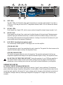
12
GPS 900/1500
150VAC Units Only
Channel A Input Source
All other GPS Models
NOTE: Always use a balanced input source if available.
NOTE: Minimum Load
Impedance is 2 Ohms.
NOTE: Minimum Load
Impedance is 2 Ohms.
GPS
™
Series Amplifiers
Recommended Connection for Stereo Mode
SP
™
7G
SP
™
7G
Channel B Input Source
1/4" jacks are wired in parallel
with binding post.
Tip = Positive
Ring = Negative
DTH
®
4215F
DTH
®
4215F
Speaker connectors are wired in
parallel with binding posts.
Pins (1+) and (2+) are wired positive.
Pins (1-) and (2-) are wired negative.
To Additional Amplifier Input
To Additional Amplifier Input
Channel A Input Source
Channel B Input Source
To Additional Amplifier Input
To Additional Amplifier Input

13
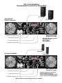
GPS 900/1500
150VAC Units Only
(-)
To negative input
terminal of speaker
(+)
To positive input
terminal of speaker
Switch “in” for
Bridge Mode
Input Source
All other GPS Models
(-)
To negative input
terminal of speaker
(+)
To positive input
terminal of speaker
NOTE: Always use a balanced input source if available.
NOTE: Minimum Load
Impedance is 4 Ohms.
NOTE: Minimum Load
Impedance is 4 Ohms.
GPS
™
Series Amplifiers
Recommended Connection for Bridged Mode
To Additional
Amplifier Input
Switch “in” for
Bridge Mode
Input Source
To Additional
Amplifier Input

14
WIRE GAUGE CHART
Stranded Power Power Power
Cable Wire Loss Loss Loss
Length Gauge Into Into Into
(Feet)
(A
WG) 8 ohms 4 ohms 2 ohms
5' 18 AWG .79% 1.58% 3.16%
16 .05 1.0 2.0
14 .31 .62 1.24
12 .20 .40 .80
10 .125 .25 .50
10' 18 AWG 1.58% 3.16% 6.32%
16 1.0 2.0 4.0
14 .62 1.25 2.50
12 .40 .80 1.6
10 .25 .50 1.0
40' 18 AWG 8% 12.6% 25.2%
16 4.0 8.0 16.0
14 2.5 5.0 10
12 1.60 3.2 6.4
10 1.0 2.0 4.0
8 .625 1.25 2.50
80' 16 AWG 8.0% 16.0% 32.0%
14 5.0 10.0 20.0
12 3.2 6.4 12.8
10 2.0 4.0 8.0

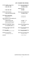
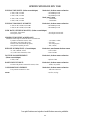
GPS
™
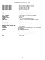
900 SPECIFICATIONS
OUTPUT POWER: (Typical value) Stereo mode, both channels driven
2 ohms, 1 kHz, .1 THD - 450 WRMS per channel
4 ohms, 1 kHz, .1 THD - 330 WRMS per channel
8 ohms, 1 kHz, .1 THD - 200 WRMS per channel
Bridge mode, mono
4 ohms, 1 kHz, .1 THD - 900 WRMS
8 ohms, 1 kHz, .1 THD - 660 WRMS
RATED OUTPUT POWER: Stereo mode, both channels driven
4 ohms, 20 Hz to 20 kHz,0.03% THD - 300 WRMS per channel
8 ohms, 20 Hz to 20 KHz,0.02% THD - 170 WRMS per channel
SLEW RATE: (Typical value)
Stereo mode, each channel - 40 Volts per usec
Bridge mode, mono - 80 Volts per usec
INPUT SENSITIVITY AND IMPEDANCE:
Input attenuator set @ FCW
@ rated output power, 4 ohms - 0.90 VRMS (-1 dBV)
Unbalanced, 1/4" phone jack - 20 k ohms
Balanced, XLR (phase selectable) - 10 k ohms per leg
Overall system gain per channel - 40X (+32 dB)
FREQUENCY RESPONSE: (Typical) Stereo mode, both channels driven
+0,-1 dB, 1 WRMS, 4 ohms - 5 Hz to 50 kHz
+0,-0.2 dB @ rated output, 4 ohms - 20 Hz to 20 kHz
DAMPING FACTOR: (Typical value) Stereo mode, both channels driven
8 ohms, 1 kHz - Greater than 400
HUM AND NOISE: Stereo mode, both channels driven
Below rated output power, 4 ohms - 100 dB @ 120 volts
POWER CONSUMPTION: Stereo mode, both channels driven
@ 1/8 rated power @ 2 ohms - 540 watts @ 120 VAC
WEIGHT: - 35.8 lbs. (16.2 kg)
15
Specifications subject to change without notice.

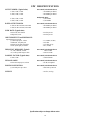
GPS
™
1500 SPECIFICATIONS
OUTPUT POWER: (Typical value) Stereo mode, both channels driven
2 ohms, 1 kHz, .1 THD - 750 WRMS per channel
4 ohms, 1 kHz, .1 THD - 550 WRMS per channel
8 ohms, 1 kHz, .1 THD - 320 WRMS per channel
Bridge mode, mono
4 ohms, 1 kHz, .1 THD - 1,500 WRMS
8 ohms, 1 kHz, .1 THD - 1,100 WRMS
RATED OUTPUT POWER:
Stereo mode, both channels driven
4 ohms, 20 Hz to 20 kHz,0.03% THD - 500 WRMS per channel
8 ohms, 20 Hz to 20 kHz,0.02% THD - 280 WRMS per channel
SLEW RATE: (Typical value)
Stereo mode, each channel - 40 Volts per usec
Bridge mode, mono - 80 Volts per usec
INPUT SENSITIVITY and IMPEDANCE:
Input attenuator set @ FCW
@ rated output power, 4 ohms - 1.17 VRMS (+1 dBV)
Unbalanced, 1/4" phone jack - 20 k ohms
Balanced, XLR (phase selectable) - 10 k ohms per leg
Overall system gain per channel - 40X (+32 dB)
FREQUENCY RESPONSE: (Typical)
Stereo mode, both channels driven
+0,-1 dB, 1 WRMS, 4 ohms - 5 Hz to 50 kHz
+0,-0.2 dB @ rated output, 4 ohms - 20 Hz to 20 kHz
DAMPING FACTOR: (Typical value) Stereo mode, both channels driven
8 ohms, 1 kHz - Greater than 400
HUM AND NOISE: Stereo mode, both channels driven
Below rated output power, 4 ohms - 100 dB, unweighted
POWER CONSUMPTION: Stereo mode, both channels driven
@ 1/8 rated power @ 2 ohms - 1080 watts @ 120 VAC
WEIGHT: - 39.2 lbs. (17.9 kg)
16
Specifications subject to change without notice.

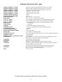
17
GPS
™
2600 SPECIFICATIONS
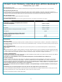
Rated Power (2 x 2 ohms) - 1,300 watts @ 1 kHz both channels driven at <0.15% T.H.D.
Rated Power (2 x 4 ohms) - 950 watts @ 1 kHz both channels driven at <0.1% T.H.D.
Rated Power (2 x 8 ohms) - 650 watts @ 1 kHz both channels driven at <0.1% T.H.D.
Rated Power (1 x 2 ohms) - 1,500 watts @ 1 kHz at <0.1% T.H.D
Rated Power (1 x 4 ohms) - 1,000 watts @ 1 kHz at <0.1% T.H.D
Rated Power (1 x 8 ohms) - 700 watts @ 1 kHz at <0.05% T.H.D
Minimum Load Impedance - 2 ohms
Maximum RMS Voltage Swing - 93 volts
Frequency Response - 10 Hz - 100 kHz; +0, -.3 dB at 1 watt
Power Bandwidth - 10 Hz - 40 kHz; +0, -3 dB at rated power
T.H.D. (2 x 2 ohms) - <0.15% @ 1050 watts from 20 Hz to 20 kHz with both channels driven
T.H.D. (2 x 4 ohms) - <0.1% @ 900 watts from 20 Hz to 20 kHz with both channels driven
T.H.D. (2 x 8 ohms) - <0.1% @ 600 watts from 20 Hz to 20 kHz with both channels driven
Input CMRR - > - 65d B @ 1 kHz
Voltage Gain - x 40 (32 dB)
Crosstalk - > -75 dB @ 1 kHz at rated power @ 8 ohms
Hum and Noise - > -110 dB, “A” weighted referenced to rated power @ 8 ohms
Power Consumption - > 1200 watts
Slew Rate - > 40V/us
Damping Factor (8 ohms) - > 700:1 @ 20 Hz to 1 kHz
SMPTE IMD - <0.1% 60 Hz and 7 kHz, 900W @ 4 ohms
Input Sensitivity (x 40) - 1.54 volts for 4 ohm rated power, 1.27 volts for 2 ohm rated power
Input Impedance - 20 k ohms, balanced
Current Draw @ 1/8 power@ 2 ohms - 10 A @ 120 volts
Cooling - Two 80 mm DC fans, off until heatsinks reach 45
0
C, then temperature dependant
variable speed
Controls - Two front panel attenuators
Indicator LEDs - Two Clip, two Signal, two Active
Protection - Thermal, DC, turn-on bursts, subsonic, incorrect loads
Connectors - XLR input, 6.3 mm phone type output patch, Speakon and Binding Post speaker
output, IEC mains input
Construction - 16 ga. steel reinforced with 12 ga.rack ears
Dimensions - 133 mm x 483 mm x 432 mm, 400 mm behind rear mounting ears
(5.23" x 19" x 17", 15.75" behind rack ears)
Weight - 45.7 lbs. (20.7 kg)
Specifications subject to change without notice.

18
Specifications subject to change without notice.
GPS 3400 SPECIFICATIONS
Rated Power (2 x 2 ohms): 1,700 watts @ 1 kHz both channels driven at <0.15% T.H.D.
Rated Power (2 x 4 ohms): 1,200 watts @ 1 kHz both channels driven at <0.1% T.H.D.
Rated Power (2 x 8 ohms): 750 watts @ 1 kHz both channels driven at <0.1% T.H.D.
Rated Power (1 x 2 ohms): 1,800 watts @ 1 kHz at <0.1% T.H.D
Rated Power (1 x 4 ohms): 1,350 watts @ 1 kHz at <0.1% T.H.D
Rated Power (1 x 8 ohms): 825 watts @ 1 kHz at <0.05% T.H.D
T.H.D. (2 x 2 ohms): <0.15% @ 1350W from 20 Hz to 20 kHz with both channels driven
T.H.D. (2 x 4 ohms): <0.1% @ 1000W from 20 Hz to 20 kHz with both channels driven
T.H.D. (2 x 8 ohms): <0.08% @ 700W from 20 Hz to 20 kHz with both channels driven
Input CMRR: > - 65 dB @ 1 kHz
Voltage Gain: x 40 (32 dB)
Crosstalk: > -75 dB @ 1 kHz at rated power @ 8 ohms
Hum and Noise: > -115 dB, “A” weighted referenced to rated power @ 8 ohms
Power Consumption: > 1400 watts
Slew Rate: > 40V/us
Damping Factor (8 ohms): > 325:1 @ 20 Hz - 1 kHz
SMPTE IMD: <0.1% 60Hz and 7 kHz, 950W @ 4 ohms
Input Sensitivity (x 40): 1.7 volts for 4 ohm rated power, 1.4 volts for 2 ohm rated power
Input Impedance: 20 k ohms, balanced
Current Draw @ 1/8 rated
power @ 2 ohms: 11.66 A @ 120 volts
Cooling: Two 80 mm DC fans, off until heatsinks reach 45
0
C, then temperature dependent variable speed
Controls: Two front panel attenuators
Indicator LEDs: Two DDT/Clip, 2 Signal, 2 Power
Protection: Thermal, DC, turn-on bursts, subsonic, incorrect loads
Connectors: XLR input, 6.3mm phone type output patch, Speakon and Binding Post speaker output, IEC mains input
Construction: 16 ga. steel reinforced with 12 ga.rack ears
Dimensions: 133 mm x 483 mm x 432 mm, 400 mm behind rear mounting ears (5.23" x 19" x 17", 15.75" behind rack ears)
Weight: 49.8 lbs. (23.3 kg)

19
GPS 3500 SPECIFICATIONS
Rated Power (2 x 2 ohms): 1750 watts @ 1 kHz both channels driven at <0.15% T.H.D.
Rated Power (2 x 4 ohms): 1200 watts @ 1 kHz both channels driven at <0.1% T.H.D.
Rated Power (2 x 8 ohms): 775 watts @ 1 kHz both channels driven at <0.1% T.H.D.
Rated Power (1 x 2 ohms): 1,850 watts @ 1 kHz at <0.1% T.H.D
Rated Power (1 x 4 ohms): 1,350 watts @ 1 kHz at <0.1% T.H.D
Rated Power (1 x 8 ohms): 850 watts @ 1 kHz at <0.05% T.H.D
Minimum Load Impedance: 2 ohms
Maximum RMS Voltage Swing: 89 volts
Frequency Response: 10 Hz - 100 kHz; +0, -.3d B at 1 watt
Power Bandwidth: 10 Hz - 40 kHz; +0, -3 dB at rated power
T.H.D. (2 x 2 ohms): <0.15% @ 1400W from 20 Hz to 20 kHz with both channels driven
T.H.D. (2 x 4 ohms): <0.1% @ 1050W from 20 Hz to 20 kHz with both channels driven
T.H.D. (2 x 8 ohms): <0.08% @ 750W from 20 Hz to 20 kHz with both channels driven
Input CMRR: > - 65 dB @ 1 kHz
Voltage Gain: x 40 (32 dB)
Crosstalk: > -75 dB @ 1 kHz at rated power @ 8 ohms
Hum and Noise: > -115 dB, “A” weighted referenced to rated power @ 8 ohms
Power Consumption: > 1400 watts
Slew Rate: > 40V/us
Damping Factor (8 ohms): > 325:1 @ 20 Hz - 1 kHz
SMPTE IMD: <0.1% 60Hz and 7 kHz, 950W @ 4 ohms
Input Sensitivity (x 40): 1.7 volts for 4 ohm rated power, 1.4 volts for 2 ohm rated power
Input Impedance: 20 k ohms, balanced
Current Draw @ 1/8 rated
power @ 2 ohms: 11.66 A @ 120 volts
Cooling: Two 80 mm DC fans, off until heatsinks reach 45
0
C, then temperature dependent variable speed
Controls: Two front panel attenuators
Indicator LEDs: Two DDT/Clip, 2 Signal, 2 Power
Protection: Thermal, DC, turn-on bursts, subsonic, incorrect loads
Connectors: XLR input, 6.3mm phone type output patch, Speakon and Binding Post speaker output, IEC mains input
Construction: 16 ga. steel reinforced with 12 ga.rack ears
Dimensions: 133 mm x 483 mm x 432 mm, 400 mm behind rear mounting ears (5.23" x 19" x 17", 15.75" behind rack ears)
Weight: 51.3 lbs. (23.3 kg)
Specifications subject to change without notice.

20
ESPAÑOL
Serie GPS
™
Amplificadores de Potencia
Felicidades por tu compra del nuevo amplificador de potencia de la serie GPS de Peavey Electronics. Años de
diseño y pruebas han producido una línea de amplificadores dinámicos completamente refinada. La serie GPS
consiste de los modelos GPS 900, GPS 1500, GPS 2600, GPS 3400 y GPS 3500. Cada modelo incluye
enfriamiento por túnel, ventiladores variables de dos velocidades, protección de iniciación y protección de
bocinas DDT‘. Pero también hay diferencias entre los modelos, como las diferencias de potencia y conexiones.
Esta guía describirá todas las características de tu modelo GPS, y también hará nota de las características
comunes entre los otros modelos GPS. La gráfica inferior ofrece una guía de referencia rápida.
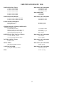
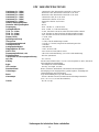
SPECIFICATIONS
OUTPUT POWER
Stereo mode, both channels driven
2 ohms, 1 kHz, 0.1% THD
4 ohms, 1 kHz, 0.1% THD
8 ohms, 1 kHz, 0.1% THD
Bridge mode, mono
4 ohms, 1 kHz, 0.1% THD
8 ohms 1 kHz, 0.1% THD
RATED OUTPUT POWER:
Stereo mode, both channels driven
4 ohms, 20 Hz to 20 kHz, 0.03% THD
8 ohms, 20 Hz to 20 kHz, 0.02% THD
4 ohms, 20 Hz to 20 kHz, 0.1% THD
8 ohms, 20 Hz to 20 kHz, 0.08% THD
SLEW RATE:(Typical value)
Stereo mode, each channel
Bridge mode, mono
INPUT SENSITIVITY &
IMPEDANCE:
@ rated output power, 4 ohms
unbalanced, 1/4" phone jack
Balanced, XLR (polarity selectable)
Overall system gain per channel
FREQUENCY RESPONSE:
Stereo mode, both channels driven
+0m -1 dB @ 1 WRMS, 4 ohms
+0, -0.2 dB @ rated output, 4 ohms
DAMPING FACTOR: (Typical
value)
Stereo mode, both channels driven
8 ohms
Hum & Noise:
Stereo mode, both channels driven
Below rated output power, 4 ohms
GPS
™
900
450W RMS per channel
330W RMS per channel
200W RMS per channel
900W RMS
660W RMS
300W RMS per channel
1700W RMS per channel
40 Volts per µsec
80 Volts per µsec
0.87V RMS
20 k ohms
10 k ohms per leg
40X (+32 dB)
5 Hz to 50 kHz
20 Hz to 20 kHz
Greater than 400
100 dB, unweighted
GPS
™
1500
750W RMS per channel
550W RMS per channel
320W RMS per channel
1500W RMS
1100W RMS
500W RMS per channel
280W RMS per channel
40 Volts per µsec
80 Volts per µsec
1.12V RMS
20 k ohms
10 k ohms per leg
40X (+32 dB)
5 Hz to 50 kHz
20 Hz to 20 kHz
Greater than 400
100 dB, unweighted
GPS
™
2600
1300W RMS per channel
950W RMS per channel
620W RMS per channel
2600W RMS
1900W RMS
900W RMS per channel
600W RMS per channel
40 Volts per µsec
80 Volts per µsec
1.54V RMS
20 k ohms
10 k ohms per leg
40X (-32 dB)
5 Hz to 100 kHz
10 Hz to 30 kHz
Greater than 700
100 dB, unweighted
GPS
™
3500
1700W RMS per channel
1200W RMS per channel
775W RMS per channel
3500W RMS
2400W RMS
1050W RMS per channel
750W RMS per channel
40 Volts per µsec
80 Volts per µsec
1.62V RMS
20 k ohms
10 k ohms per leg
40X (+32 dB)
5 Hz to 100 kHz
10 Hz to 30 kHz
Greater than 325
100 dB, unweighted
Por favor lee esta guía completamente. Presta especial atención a las varias advertencias incluidas, ya que
éstas son para tu protección y la de tu equipo. Cada sección comenzará con una pequeña descripción de la
información que puedes esperar recibir en ella. Esto te servirá para localizar rápidamente la información que
requieres. Una vez más, ¡felicidades y gracias por comprar productos Peavey!
DESENPAQUE/REGISTRO
Inspecciona el amplificador durante el desempaque. Si encuentras averías, avísale a tu distribuidor
inmediatamente. Asegúrate de guardar el cartón y todos los materiales de empaque. Si alguna vez tienes que
mandar el equipo a Peavey o a un centro de servicio o distribución autorizado, usa sólo los materiales de
empaque originales. Por favor llena la tarjeta de registro en este momento. Es importante que la llenes en su
totalidad y la envíes a Peavey Electronics para que tu garantía sea aplicable.
Page is loading ...
Page is loading ...
Page is loading ...
Page is loading ...
Page is loading ...
Page is loading ...
Page is loading ...
Page is loading ...
Page is loading ...
Page is loading ...
Page is loading ...
Page is loading ...
Page is loading ...
Page is loading ...
Page is loading ...
Page is loading ...
Page is loading ...
Page is loading ...
Page is loading ...
Page is loading ...
Page is loading ...
Page is loading ...
Page is loading ...
Page is loading ...
Page is loading ...
Page is loading ...
Page is loading ...
Page is loading ...
Page is loading ...
Page is loading ...
Page is loading ...
Page is loading ...
Page is loading ...
Page is loading ...
Page is loading ...
Page is loading ...
Page is loading ...
Page is loading ...
Page is loading ...
Page is loading ...
Page is loading ...
Page is loading ...
Page is loading ...
Page is loading ...
Page is loading ...
Page is loading ...
Page is loading ...
Page is loading ...
Page is loading ...
Page is loading ...
Page is loading ...
Page is loading ...
-
 1
1
-
 2
2
-
 3
3
-
 4
4
-
 5
5
-
 6
6
-
 7
7
-
 8
8
-
 9
9
-
 10
10
-
 11
11
-
 12
12
-
 13
13
-
 14
14
-
 15
15
-
 16
16
-
 17
17
-
 18
18
-
 19
19
-
 20
20
-
 21
21
-
 22
22
-
 23
23
-
 24
24
-
 25
25
-
 26
26
-
 27
27
-
 28
28
-
 29
29
-
 30
30
-
 31
31
-
 32
32
-
 33
33
-
 34
34
-
 35
35
-
 36
36
-
 37
37
-
 38
38
-
 39
39
-
 40
40
-
 41
41
-
 42
42
-
 43
43
-
 44
44
-
 45
45
-
 46
46
-
 47
47
-
 48
48
-
 49
49
-
 50
50
-
 51
51
-
 52
52
-
 53
53
-
 54
54
-
 55
55
-
 56
56
-
 57
57
-
 58
58
-
 59
59
-
 60
60
-
 61
61
-
 62
62
-
 63
63
-
 64
64
-
 65
65
-
 66
66
-
 67
67
-
 68
68
-
 69
69
-
 70
70
-
 71
71
-
 72
72


Ask a question and I''ll find the answer in the document
Finding information in a document is now easier with AI
in other languages
- français: Peavey GPS Manuel utilisateur
- español: Peavey GPS Manual de usuario
- Deutsch: Peavey GPS Benutzerhandbuch
Related papers
-
Peavey GPS Series Power Amplifier Owner's manual
-
-
-
-
-
-
 Peavy PV Series Power Amplifer Owner's manual
-
-
-
