®
ELECTRIC
CONVEYOR OVEN
230V MODELS
UM1833A
UM1850A
UM1850A
Installation and
Operation
Instructions
2M-Z9845 Rev B 2/9/07
®
®
®
®

2
These symbols are intended to alert the user to the presence of
important operating and maintenance instructions in the manual
accompanying the appliance.
RETAIN THIS MANUAL FOR FUTURE REFERENCE
NOTICE
Using any part other than genuine Star factory supplied parts relieves the
manufacturer of all liability.
Star reserves the right to change specifi cations and product design without
notice. Such revisions do not entitle the buyer to corresponding changes,
improvements, additions or replacements for previously purchased
equipment.
Due to periodic changes in designs, methods, procedures, policies and
regulations, the specifi cations contained in this sheet are subject to change
without notice. While Star Manufacturing exercises good faith efforts to provide
information that is accurate, we are not responsible for errors or omissions
in information provided or conclusions reached as a result of using the
specifi cations. By using the information provided, the user assumes all risks in
connection with such use.
MAINTENANCE AND REPAIRS
Contact your local dealer for service or required maintenance. Please record the model number, serial
number, voltage and purchase date in the area below and have it ready when you call to ensure a faster
service.
SAFETY SYMBOL
Model No.
Serial No.
Voltage
Purchase Date

SPECIFICATIONS
UM1833A-230V
Rating/Connection: 6,600 Watts (3 x 2,000W element assembly)
Terminal block supplied (L1, L2, L3, N, Ground)
Electrical Supply: Separate service per oven - 15 Amp, 400/230 VAC, 3 phase, 50 Hz
Approximate Weight (1833 Oven with Legs): Installed - 180 Lbs (81.8 kg), Shipping - 210 Lbs (95.5 kg)
Dimensions: Width: 51.2" (130.0 cm) - Oven with Shelves
Depth: 30.4" (77.2 cm)
Height: 20.0" (50.8 cm) - Single Oven with Legs
36.0" (91.4 cm) - Double Oven with Legs
Recommended Minimum Clearances:
Rear of Oven to Wall 0" (0 cm)
Conveyor Extensions to Wall 6" (15.2 cm)
UM1850A-230V
Rating/Connection: 6,600 Watts (3 x 2,000W element assembly)
Terminal block supplied (L1, L2, L3, N, Ground)
Electrical Supply: Separate service per oven - 15 Amp, 400/230 VAC, 3 phase, 50 Hz
Approximate Weight (1850 Oven with Legs): Installed - 210 Lbs (95.5 kg), Shipping - 240 Lbs (109.1 kg)
Dimensions: Width: 50.0" (127.0 cm)
Depth: 30.4" (77.2 cm)
Height: 20.0" (50.8 cm) - Single Oven with Legs
36.0" (91.4 cm) - Double Oven with Legs
Recommended Minimum Clearances:
Rear of Oven to Wall 0" (0 cm)
Conveyor Extensions to Wall 6" (15.2 cm)
2

GENERAL INFORMATION
This equipment is designed and sold for commercial use only by personnel trained and
experienced in its operation and is not sold for consumer use in and around the home nor for
use directly by the general public in food service locations.
First and foremost, each crate should be examined before signing the Bill of Lading to report
any visible damage by the trucker in transit and to account for the proper number of crates.
If there is apparent damage, arrangements should be made to le a claim against the carrier.
Interstate
Commerce Regulations require that the claim must be initiated by the consignee.
Proper and secure storage facilities should be arranged for the oven(s) if necessary to protect
it from outdoor or damp conditions at all times before installation.
-IMPORTANT-
When you have all the crates unloaded, open the crates and remove all plastic covers.
Inspect at once for concealed damage. If anything appears to be damaged, contact the
appropriate persons immediately to le a damage claim. After completing this inspection,
nish unpacking the oven. Be sure to remove all paper protection and packing material
from the unit prior to heating.
CAUTION
FOR YOUR SAFETY DO NOT STORE OR USE GASOLINE OR OTHER FLAMMABLE
VAPORS AND LIQUIDS IN THE VICINITY OF THIS OR ANY OTHER APPLIANCE.
-IMPORTANT-
THIS APPLIANCE MUST BE INSTALLED BY QUALIFIED PERSONS AND INSTALLED
IN ACCORDANCE WITH THE RULES IN FORCE WITHIN THE COUNTRY OF
DESTINATION.INSTALLATION
The ovens are equipped for the voltage indicated on the nameplate mounted on the rear of
the control box. They will operate on alternating current (AC) only. A cord bushing is supplied
in the bottom of the control box. This allows the installer-supplied cord to be connected to the
terminal block connections located behind the rear access door. The oven must be connected
to power per all applicable codes. A means of disconnecting the oven from power should be
supplied for safety and ease of maintenance.
-IMPORTANT-
The appliance must be positioned so the plug is accessible. A hormonized, 300/500V,
oil-resistant, exible cord with 65°C minimum ratings must be used. Choose appropriate
conductors in relation to the length of the cord (1.0 square mm minimum) and operating
conditions (i.e. temperature).
WARNING
DO NOT CONNECT TO DIRECT CURRENT (DC).
Installation of the electric oven should conform to the:
NATIONAL ELECTRIC CODE AND ALL LOCAL ELECTRIC CODES AND
ORDINANCES AND THE LOCAL ELECTRIC COMPANY RULES AND
REGULATIONS.

PURCHASER'S RESPONSIBILITY
It is the responsibility of the purchaser:
1. To see that the electric services for the oven are installed on site in accordance with the
manufacturer's specications.
2. To unload, uncrate, and install the oven in its proper location and in accordance with this
installation operation manual.
3. To see that electric services are connected properly by a qualied installer of your choice.
All such connections must be in accordance with applicable code requirements.
4. To arrange for inspection and operation check-out by an authorized service technician.
The warranty becomes effective upon verication of proper installation.
IMPORTANT SAFETY INFORMATION
Do not attempt to operate the oven until connection of utility service has been fully inspected
by an authorized service technician or a Star Service Representative. This service is required
by Star in order to assist the purchaser in proper start-up of the oven on site. Please note the
specic details on the Warranty and make certain that service connections are made to proper
utility
services.
The warranty shall not apply if the oven is started up and operated prior to the utilities and oven
being inspected and check-out made by an authorized service technician or a Star Service
Representative.
CAUTION
IMPROPER INSTALLATION, ADJUSTMENT, ALTERATION, SERVICE, OR
MAINTENANCE CAN CAUSE PROPERTY DAMAGE, INJURY, OR DEATH. READ
ALL INSTRUCTIONS THOROUGHLY BEFORE INSTALLING OR SERVICING THIS
EQUIPMENT.
CAUTION
Minimum clearances must be maintained from all walls and combustible materials. Minimum
clearances for this unit should be 0 inches from the rear (rear bumpers provided must be in
place) and 6 inches from both sides. Keep the oven free and clear of all combustible material.
CAUTION
Do not obstruct the ventilation holes in the control panels as these provide cooling air for the
controls.
WARNING
The oven is to be operated only on the type of electricity shown on the specication plate.
INSTALLATION INFORMATION
THE INSTALLATION INSTRUCTIONS CONTAINED HEREIN ARE FOR THE USE OF
QUALIFIED INSTALLATION AND SERVICE PERSONNEL ONLY. INSTALLATION OR
SERVICE BY OTHER THAN QUALIFIED PERSONNEL MAY RESULT IN DAMAGE
TO THE OVEN AND/OR INJURY TO THE OPERATOR.
Qualied installation personnel are individuals, a rm, a corporation, or a company which either
in person or through a representative are engaged in and responsible for:
1. The installation of electrical wiring from the electric meter, main control box, or service outlet
to the electric appliance.
Qualied installation personnel must be experienced in such work, familiar with all precautions
r
equired, and have complied with all requirements of state or local authorities having
jurisdiction.

LOCATION
The well-planned and proper placement of your oven will result in long-term operator convenience
and satisfactory performance. It is essential that an adequate air supply to the oven be
maintained to provide a sufcient ow of ventilation air. Follow these guidelines:
1. Place the oven in an area that is free of drafts.
2. Keep the oven area free and clear of all combustibles such as paper, cardboard, ammable
liquids, and solvents.
3. Do not place the oven on a curb base or seal to a wall. This will restrict the ow of air and
prevent proper ventilation to the blower motors. This condition must be corrected to prevent
permanent damage to the oven.
4. On all models, tripping of the blower motor's thermal overload device indicates an excessive
ambient temperature at the back of the oven. This condition must be corrected to avoid
permanent damage to the oven.
This appliance must be installed on a
sturdy counter or stand using the feet
provided for cleaning clearance. As
a minimum, 24" of clearance on the
discharge end of the oven should be
allowed for removal of the conveyor
assembly if the oven is not on a mobile
cart. Also allow room for a service
technician to access the control box
door and the fan motor cover over
the rear of the oven if the oven is not
movable.
CAUTION
Any surface the oven is mounted on should have a raised area around the perimeter to prevent
the oven from accidentally sliding off the edge. Serious injury or death could occur if the oven
falls on a person.
CAUTION
Any cart that the oven is mounted on must be deep and wide enough to provide a stable
platform. A cart with a narrow stance could allow the oven to tip over, causing property damage
or serious harm to people.

VENTILATION
Local codes prevail. These are the "authority having jurisdiction" as stated by the National
Fire Protection Association, Inc. in NFPA 96-Latest Edition. For further ventilation information
see below.
A ventilation hood may be required to remove heat and cooking odors. The hood and HVAC
installation must meet local codes to gain approval by the authority having jurisdiction.
Requirements may vary throughout the country depending on the location by city, county, and
state. Obtain information from the authority having jurisdiction to determine the requirements
for your installation. Obtain information and review copies of codes or documents that will
be used to inspect and approve your installation. Your ventilation hood supplier and HVAC
contractor should be contacted to provide guidance.
CAUTION
Prevent airow through the cooking tunnel. Air must NOT be directed onto the oven's
front or rear or to the sides of the cooking area. This can cause incomplete or uneven
baking and increased energy consumption.
ELECTRICAL CONNECTION
Before making any electrical connections to this unit, check that the power supply is adequate
for the voltage, amperage, and phase requirements stated on the rating plate. A wiring diagram
is included herewith.
When installed, this appliance must be electrically grounded and its installation must comply with
the National Electric Code, ANSI-NFPA 70, latest version, manufacturer's installation instructions,
and applicable local municipal building codes. In Canada, all electrical connections are to be
in accordance with CSA C22.1 - Canadian Electrical Code Part 1 and/or local codes.
This appliance is equipped with a ve-pole terminal and cord bushing to which the
c
ustomer/installer can attach. Each line (L1, L2, L3) should have 230V potential referenced
to the neutral (N) connection. An earth (ground) connection is also provided for a ve-
wire system.

STACKING INSTRUCTIONS
The following instructions should be followed when stacking more
than one unit.
Single Oven (or Bottom) Cart Install:
1. Remove door, conveyor, and nger assemblies.
2. Unbolt unit from shipping crate (4 bolts).
3. Turn unit on front as shown.
4. Thread the four legs into the bottom of the oven.
5. CAREFULLY lift oven upright.
Stacked Oven Install Preparation:
1. Remove door, conveyor, and nger assemblies.
2. Unbolt unit from shipping crate (4 bolts).
3. Turn unit on front as shown.
4. Remove top of lower oven (4 screws total, 2 each front and
rear) and bolt to stacked oven base using 3/8 - 16 bolts.
5. Place top oven on lower unit and re-attach with screws for
top of lower oven.
OPERATING INSTRUCTIONS
DO NOT ATTEMPT TO OPERATE THE OVEN until connection
of utility service and installation has been fully inspected (start-up
check-out) by an authorized service technician or a Star Service
Technician in order to assure the oven is properly installed and
in working order. The warranty becomes effective upon
verication of proper installation.
CAUTION
DO NOT WORK AROUND THE CONVEYOR BELT
WITH LONG HAIR, LOOSE CLOTHING, OR DANGLING
JEWELRY. GETTING CAUGHT IN THE BELT COULD
RESULT IN DISMEMBERMENT OR FATAL INJURY.
Unless specied otherwise, conveyor travel is factory set for
left to right operation when facing the front of the oven. If a
direction change is required, refer to "DISPLAY INFORMATION,"
section 3 for instructions on how to program the controller for
a direction change. In addition, the conveyor belt must be
changed to travel in the new direction.
SAFETY OPERATING INSTRUCTIONS
The information contained in this section is provided for the use of qualied operating personnel.
Qualied operating personnel are those who have carefully read the information contained in
this manual, are familiar with the functions of the oven and/or have had previous experience
with the operation of the equipment described. Adherence to the procedures recommended
herein will assure the achievement of optimum performance and long, trouble-free service.

Please take time to read the following safety operating instructions. They are the key to
the successful operation of your Ultra-Max Conveyor Oven.
To adjust the time and temperature:
1. Press the DOWN and UP arrows ( ) at
the same time. Hold for four seconds until
the TEMPERATURE display goes blank.
2. Press the ENTER button (
) to switch
between TIME and TEMPERATURE.
3. Press the UP arrow (
) to increase or the
DOWN arrow (
) to decrease the TIME or
TEMPERATURE. Hold either button down
for faster display changes.
4. After ve seconds, the new numbers will
be saved and the oven will display the new
settings.
To turn the oven off:
1. Push the power switch to "OFF." The
oven is equipped with a cool-down feature
for motor shaft and bearing protection.
This enables the blower motor(s) to run
regardless of the controller status. The
blower(s) continue to run until the oven
cools to a safe temperature.
3) Press the up button ( ) to increase
or the down button ( ) to decrease
TIME or TEMPERATURE. Hold
button down for faster display
changes.
4) After five seconds, the new numbers
will be saved and the oven will display
new settings.
4) Après cinq secondes, les nouveaux
nombres seront sauvés et le four montrera
de nouveaux arrangements.
3) Tenez "vers le haut" bouton ( ) pour
augmenter ou "vers le bas" boutonnez ( )
pour diminution de le TEMPS ou
TEMPÉRATURE. Maintenez le bouton pour
des changements plus rapides.
A Star Manufacturing Company
2) Press the enter button ( ) to
switch between TIME and
TEMPERATURE.
Push power switch "ON."
To Start:
2) Appuyez sur le bouton de "entrée" ( )
pour commuter entre le TEMPS et la
TEMPÉRATURE.
1) Tenez "vers le haut" et "vers le bas"
boutonne ( ) en même temps. Tenez
les boutons pendant quatre secondes
jusqu'à ce que l'affichage de la
TEMPS soit blanc.
Après cinq minutes, nouvelle tentative.
Si le brûleur n'allume pas en une minute,
poussée le commutateur de puissance dans
la position de "ARRÊTE" et attend 5 minutes.
Poussez le commutateur de puissance à
"MARCHE."
OFF / ARRÊTE
Ajustement du TEMPS et de la
TEMPÉRATURE:
Pour Commencer:
ON / MARCHE
“HEAT” LIGHT
“TIME” LIGHT
If burner does not light in one minute
push the power switch to the "OFF"
position and wait five minutes.
1) Press the up and down buttons
( ) at the same time, hold for four
seconds until TIME display is blank.
Adjusting TIME and TEMPERATURE:
After five minutes, retry.
SAFETY TIPS
For your safety, read before operating.
If you smell gas:
1. DO NOT try to light any appliance.
2. DO NOT touch any electrical switches.
3. Use an exterior phone to call your gas
supplier immediately.
4. If you cannot reach your gas supplier, call
the re department.
In the event of a power failure:
1. Turn all switches off.
2. DO NOT attempt to operate the oven until
the power is restored.
General Safety Tips:
1. If the oven needs to be moved for any
reason, the power must be disconnected
from the unit before doing so.
2. DO NOT remove the control box cover
unless the oven is unplugged.
OPERATION
To turn the oven on:
1. Push the power switch to "ON."
2. After the fan begins to build pressure,
the pressure switch will provide power to
the control board to engage the heating
element contactor. You should hear an
initial "click" from the contactor as it begins
to heat.

DISPLAY INFORMATION
When operating the oven, there are three levels of
access:
1. Store Level - General employees would know
these functions and how to change them. While
the oven is running, enter this mode by holding the
DOWN and UP arrows (
) simultaneously for
four seconds. The TIME display goes blank and
the TEMP setpoint is displayed. Adjust with the
DOWN or UP arrows. The ENTER button (
)
toggles between TIME and TEMP. The parameter
that can be adjusted is displayed, the other is
blank. When TIME and TEMP are adjusted as
needed, wait ve seconds and SAVE is displayed.
The values are accepted and the controller begins
controlling to these new values. The conveyor
continues to operate at the same speed until a
new value is accepted. The temperature control
output should be OFF during changes.
2. Manager Level - This is a lock so that TIME and
TEMP cannot be changed even at the Store Level.
While the oven is running, enter this mode by
holding the DOWN and UP arrows simultaneously
for 4 seconds. The TIME display goes blank and
the TEMP setpoint is displayed. Release the
UP arrow and continue to hold the DOWN arrow
for an additional 4 seconds. The TEMP display
shows LOC as the TIME display shows nO, which
indicates that the TIME/TEMP parameters can be
changed after reaching the STORE level.
yES indicates that the parameters cannot be
changed even after entering the STORE level.
The LOC setting can be toggled using the ENTER
button (
).
ADDITIONAL FUNCTIONS
The conveyor belt direction and the temperature
display can be changed on the conveyor oven
by a qualied technician. To change the belt
direction, the technician must reverse the motor
direction and rotate the conveyor belt for proper
oven function. A technician can also change the
temperature display from Fahrenheit to Celsius.
These changes can be made by the technician
during the start-up/check-out or at a later date.
ERROR CODES
Error codes will display as ashing text messages for
diagnostic purposes. Any temperature or thermocouple
error should turn the temperature output OFF and leave
the conveyor running at the same speed. The belt
error should turn the temperature output OFF. The
speed error should display when the motor is unable
to settle at the chosen speed. This might occur if a
fast speed is chosen that the motor is unable to spin
fast enough to achieve. The speed signal output will
remain the same but the display will ash the error
message.

BAKE TIME VERSUS TEMPERATURE
1. Bake time is actually conveyor speed and is dened
as the time the product is actually in the oven.
This is measured by noting the time when the
leading edge of the product enters the oven and
the time the leading edge of the product leaves
the oven. This is adjusted by using the conveyor
speed controller.
2. Bake temperature is adjusted by changing the
setpoint of the temperature controller to the desired
bake temperature. When the oven reaches the
desired temperature, the red dot in the lower right
corner of the temperature display will turn off and
on as the controller maintains the temperature.
3. When establishing a bake time and temperature
for a given product, the general rule shall be as
the bake time increases the bake temperature
decreases and the reverse is also true; increase
temperature, decrease time. However, there
are limits to the above rule. Going to extremes
will result in a burnt exterior and raw interior or
it will result in a very light color but over-baked
product.
4.
Once a good bake has been established, the ne
adjustments should be made by holding either
the bake time or bake temperature constant, then
varying the other.
CONVEYOR SPEED
Bake Time (Conveyor Speed) - As stated previously, bake
time (conveyor speed) is dened as the amount of time
elapsed between the time the leading edge of the product
enters the oven and the leading edge of the product exits
the oven. Bake time is controlled by adjusting the digital
speed controller. The setting on the control panel indicates
the actual bake time.
Bake time will be the same for any size product.
TIME OF DELIVERY
The time of delivery is the amount of elapsed time between
the period when the leading edge of the product enters the
oven and the trailing edge of the product is fully discharged
and is ready to be delivered to the customer.
Time of delivery changes if the product size
changes.
Tip: Train yourself not to pull the product out of the oven
when the leading edge comes out. Always wait until the
entire product has passed under the air nozzle holes - the
product needs this time to fully bake.

CLEANING INSTRUCTIONS
Follow this recommended cleaning schedule for proper oven performance:
CAUTION
DISCONNECT THE POWER SUPPLY BEFORE SERVICING OR CLEANING THIS OVEN.
SAFEGUARD THE POWER SO IT CANNOT BE ACCIDENTALLY RESTORED. FAILURE
TO DO SO COULD RESULT IN DISMEMBERMENT, ELECTROCUTION, OR FATAL INJURY.
THERE
IS MORE THAN ONE POWER SUPPLY CONNECTION POINT WHEN OVENS ARE
STACKED, SO MAKE SURE THAT ALL SWITCHES ARE IN THE OFF POSITION BEFORE
CLEANING
OR MAINTENANCE.
No electrical components should be subjected to moisture. It is therefore important that the
oven is wiped down carefully. NEVER throw
buckets of water over the oven or subject it to
pressure washing from a hose or a pressure spray. If water or other liquid is spilled on the
oven, make sure that none of it has entered the control box area before switching the oven
ON. If in doubt, call your service company.
CAUTION
Adhere to the following warnings when cleaning or maintaining your conveyor oven:
1. The oven must be cool. Do not use power cleaning equipment, steel wool, or wire brushes
on stainless steel surfaces.
2. Do not use a caustic or an alkaline base cleaner on the interior of the oven.
This will ruin the aluminized nish of the oven interior.
3.
When using cleaning solutions, be sure they meet local and national health standards.
DAILY
1. Clean the conveyor belt using a nylon brush. Allow any foreign material to drop into the
crumb pans.
2. Empty and clean the crumb pans. Use a hot water and detergent mix.
Rinse with clean water.
EVERY MONTH
1. Brush and clean the guard on the motor cooling fan.
2. Unplug the oven.
3. Remove the crumb pans.
4. Remove the conveyor assembly.
5. Unlatch and remove the front door. First remove all Bafes then Finger Assemblies.
See instructions next page.
6. Clean the oven interior with an appropriate oven cleaner.
7. Clean the conveyor assembly, crumb pans, and other removable components.
Wash in a hot water, detergent mix and rinse with clean water. For difcult cleaning
areas, use a heavy-duty de-greaser or oven cleaner.
8. Move the oven and clean under it. Be careful not to damage the oven's electrical cord or
plug when moving.
9. Reassemble the oven, being certain to include all Finger Assemblies and the Upper &
Lower Bafes.
Be certian the Lower Bafe Flange is properly positioned behind the Rear Oven Wall, as
well as the Upper Bafe is in position against the Upper Bafe Seat, as shown.
EVERY TWELVE MONTHS
A factory authorized service person should:
1. Open and clean the inside of the control box.
2. Check and tighten all electrical components.
If maintenance is required, contact your local service company, a factory
representative, or Star Manufacturing.
11

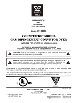
Bafe & Finger Removal / Installation
1
2
3
IL1190
4
LOWER BAFFLE
UPPER BAFFLE
Removing Finger Assemblies
1. Once cooled, REMOVE conveyor assembly and door.
2. Life up and remove Upper & Lower Bafes as shown in Step 1.
3. Slide Finger Assembly out of unit as shown in Step 2.
4. Lift Assembly apart as shown in Step 3. and wash in a hot water, detergent mix and rinse
with clean water
. For difcult cleaning areas, use a heavy-duty de-greaser or oven cleaner.
Reassemble Finger Assemblies
1. Reassemble nger assemblies and install in unit.
2. Properly install Bafes as shown in Step 4.
CAUTION
BE CERTAIN THE LOWER BAFFLE IS PROPERLY INSTALLED BEHIND THE REAR
PANEL SO NOT TO INTERFERE OR DAMAGE CONVEYOR ASSEMBLY.
3. Reinstall conveyor & door assembly, and test unit for proper operation.
12

CONVEYOR BELT TENSION
The conveyor belt of the Ultra-Max Conveyor Oven
does not have a tension adjustment. If the belt
becomes too loose, a link will have to be removed
to tighten. A belt that is too tight will also cause
operational problems due to excessive drag. We
suggest that you have a qualied service technician
perform
this adjustment.
CAUTION
Careful consideration should be exercised prior
to removing a belt link because a belt that is too
tight will impede the smooth operation of the
conveyor.
CONVEYOR BELT LINK REMOVAL
An entire link can be removed with the conveyor
assembly either in or out of the oven. This may be
necessary as the belt stretches after continuous
use. Following are the necessary steps for removing
links:
1. Move the splice clips to either end of the oven for
easy access.
2. Unhook the splice clips using long nose pliers.
3. Unhook the full link to be removed and slide it out.
Do not discard the link removed as it may be used
for making spare splice clips.
4. Reconnect the inside splice clips.
5. Reconnect the outside splice clips.
6. Replace all parts removed from the oven.
7. Straighten any bent wires to ensure smooth
sprocket engagement.
13
Remove the outside master links on the right
and left sides of the conveyor belt. Remove the
center splice clips next.
Unhook the end loop and pull up on the link
section. Save this link as it may be used for
making splice clips.
Check the orientation of the splice clips (the hooks
should be up). The belt shown is the top section,
ready for left-to-right travel.

INTERNATIONAL ONE (1) YEAR EQUIPMENT WARRANTY
All workmanship and materials in “STAR” products are warranted for a period of one year from the date shipped from the factory or
one year from the date shown on the proof of purchase of the end-user when purchased through an authorized “STAR” dealer/dis-
tributor in a commercial foodservice location.
“STAR’s” obligation under this warranty is limited to the replacement of the defective part(s) only without charge. This warranty is
void if damage occurs from improper installation, misuse or abuse, disassembly or tampering of unit for any purpose other than repair
by a qualifi ed service agent, wrong voltage, incorrect or fl uctuating voltage conditions, wrong gas, improper gas or gas conditions,
operated contrary to the installation and operating instructions, operated in an application for which the unit is not suited, or if the unit
is not maintained and/or cleaned in a suitable manner.
Any expense in connection with installation, or any cost of making adjustments on a unit to conform to electric or gas service at the
point of installation, are not covered by this warranty.
* The warranty period for the JetStar series six (6) ounce popcorn machines is two (2) years.
* The warranty period for the Chrome-Max Griddles is fi ve (5) years on the griddle surface. See detailed warranty provided with unit.
* The warranty period for Tefl on/Dura-Tec coatings is one year under normal use and reasonable care. This warranty does not
apply if damage occurs to Tefl on/Dura-Tec coatings from improper cleaning, maintenance, use of metallic utensils, or abrasive
cleaners. This warranty does not apply to the “non-stick” properties of such materials.
* This warranty is not valid on Conveyor Ovens
unless a “start-up/check-out has been performed by a Factory Authorized Technician.
In order to make a claim under this warranty; a warranty report must be fi led with Star Manufacturing International Inc. in St. Louis,
Missouri, U.S.A. by the dealer/distibutor through which product was purchased. All details, including serial number and model num-
ber of the defective unit, must be included. Failure to fi le a claim within a 120 Day time period may result in the claim being refused.
“STAR” may forego the necessity of returning the part for inspection dependent upon the expense involved. However, “STAR”
requires defective parts to be held in the claimant’s possession for a period of ninety (90) days for possible inspection by a “STAR”
representative or designated inspector .
The foregoing warranty is lieu of any and all other warranties, expressed or implied, and constitutes the entire warranty.
PARTS WARRANTY
Parts that are sold for out-of-warranty repair are warranted for a period of ninety days. The part only is warranted; no labor.
SERVICES NOT COVERED BY WARRANTY
1. Labor
2. Mileage and/or travel time
3. Installation and/or adjustment of equipment
4. Operation contrary to the installation and operating instructions
5. Cleaning of equipment
6. Seasoning of griddle plates
7. Voltage conversions/adjustments
8. Gas conversions
9. Pilot light conversion/adjustments
10. Thermostat calibration/adjustments
11. Resetting of circuit breakers or safety controls
12. Replacement of bulbs/lamps
13. Replacement of fuses
14. Damages due to improper installation
15. Damages from abuse or misuse
16. Damage created by acts of God, Acts of War, or Civil Disturbance
08-05 rms

1,2: AC IN
3: FG
4,5: -V OUT
6,7: +V OUT
1 24VDC RETURN (COMMON)
7 +24VDC
2 DIRECTION
3 ENABLE (ACTIVE LOW)
4 FAULT (ACTIVE LOW)
5 COMMON
6 COMMON
8 TACH (12 PPR)
9 VOLTAGE INPUT (SPEED)
10 +5V (USE FOR SPEED POT ONLY)
11 BRAKE (ACTIVE LOW)
12 COMMON
PS
XF1
GM/C
GM/C
C1
DSIC
PS
M1
OCB
TS1
TL2
TL1
CB
SE
FS
DS
S1
XF1
CON
TB
CB
- GEARMOTOR & CONTROLLER
- CAPACITOR, CIRC FAN MOTOR
- DIRECT SPARK IGNITION CONTROLLER
- POWER SUPPLY, 24VDC 150W PS
- MOTOR, CIRC FAN
- OVEN CONTROL BOARD
- COOL DOWN T-STAT
- CONTROL BOX TEMP LIMIT (MAN RESET)
- COOK CHAMBER TEMP LIMIT (BULB & CAP)
- CIRCUIT BREAKER
- SPARK ELECTRODE
- FLAME SENSOR
- DIFFERENTIAL PRESSURE SWITCH
- SWITCH, MAIN
- TRANSFORMER, 230V-24V
- CONTACTOR
- TERMINAL BLOCKS (2)
- CONNECTION BLOCK
TL1
TS1
TL2
361320
41
12
3
4
5
6
7
20
27
28
X
X
X
12
11
10
9
8
7
1
2
3
4
5
6
13
42
29
X
X
12
BLK
BRN
BLU
M1
C1
TL2
TS1
6
4
2
1
3 5
24V
L2 L1
7
19
7
6
DS
32
2
S1
8
30
15
25
14
TB
5
4
_
8 9
36
10
_
19
21
41
21
_
_
_
30
18
BLU
15
9
32
SET VOLTAGE TO 230V
BEFORE INSTALLING
46
3
3325
17
BLK BRN
L3
L2
14
3938
34 23
PLUG ON BACK OF MOTOR
IS SHOWN ROTATED 180°
T/C
CONTACTOR
10
PR
17
208V
230V
"L" "H"
DS
C
NC
NO
FUSE BLOCK
(2) @ 5A
18
1
3x2000W COILS
J1
J1
14
38
39
40
16
L1
40
16
37
37
NOTES:
FOR FIELD WIRING BY INSTALLER WITH CORD OR FLEXIBLE
CONDUIT. (2) EXTRA J1 JUMPERS FOR SINGLE PHASE USE
(TIE L1,L2,L3 TOGETHER) WRAP THESE WITH OTHER LOOSE
SHIP PARTS
L3N L2 L1
3
5
4 2 1
45
44
43
46
43
44
45
4
C
42
CN3
TO MOTOR
6 = COM
5 = ENABLE
4 = DIR
3 = SPEED
2 = COM
1 = TACH
27
28
12
1
CN3
X
29
CN5 TO
SMALL MOTOR
7 = SPEED (GRD)
6 = SPEED SIGNAL
5 = SPEED (5V REF)
4 = (NOT USED)
3 = TACH (GND)
2 = TACH (+5V)
1 = TACH SIGNAL
OCB
SECOND GENERATION
1
CN1 T/C TYPR K
YEL(+) RED(-)
SH (SHIELD)
CN1
CN2 (24V)
INPUT
2 = N
1 = H
CN4
_
1
23
34
CN2
1
33
25
CN4
OUTPUT TO
SOLENOID
3 = COM
2 = 24V
1 = N/C
R
RDL
A 09/15/03
B 03/26/04
RDL
C 9/23/04
CG
MATERIAL
DR.
FINISH
MODEL NO.
TITLE
PART NO.
STAR MFG. INTERNATIONAL, INC.
#10 SUNNEN DRIVE, ST. LOUIS, MO. 63143, USA
TOLERANCES UNLESS OTHERWISE NOTED
DESCRIPTION OF CHANGE
FRACTIONS ±1/64 DECIMALS ±.005 ANGLES ±1°
THIS DRAWING CONTAINS INFORMATION CONFIDENTIAL TO STAR MFG. INT'L INC.
NO REPRODUCTION OR DISCLOSURE OF ITS CONTENTS IS PERMITTED.
DR
REVISIONS
CK.
---
---
UM-1833
SK-1987
WIRING DIAGRAM, 400/230
RDL 04/30/03
LTR DATE
DATE
BL
ADD 2ND GENERATION CONTROLLER
SHOW BEND IN T/C FOR NEW MOUNT
UPDATED OVEN CONTROL BOARD
TL1

10
9
14
15
20
17
18
19
25
28
27
30
31
22
23
23
1
13
5
8
A Star Manufacturing Company
4) After five seconds, the new numbers will be saved and the oven
will display new settings.
If burner does not lght in one minute push the power
Adjusting TIME and TEMPERATURE:
2) Press the enter button ( ) to switch between TIME
1) Press the up and down buttons (
Ý ß
) at the same time,
hold for four seconds until TEMPERATURE display goes blank.
3) Press the up button (
Ý
) to increase or the down button (
ß
) to
decrease TIME or TEMPERATURE. Hold button down for
switch to the"OFF" position and wait five minutes.
To Start:
Push power switch "ON".
After five minutes, retry.
and TEMPERATURE.
faster display changes.
ON
OFF
6
26
29
34
32
35
33
7
A Star Manufacturing Company
2
3
21
NOTE:
CENTER DRIVE SHAFT,
CRUMB TRAYS,
AND PAN STOP
1850 MODEL ONLY
NOTE:
CONVEYOR SHELVES
1833 MODEL ONLY
4
12
11
STAR MANUFACTURING INTERNATIONAL, INC.
MODEL UM1833A / UM1850A
SK2235 REV. - 2/9/07
MAIN ASSEMBLY
SOME ITEMS ARE INCLUDED FOR ILLUSTRATIVE PURPOSES ONLY AND IN CERTAIN
INSTANCES MAY NOT BE AVAILABLE.
THIS DRAWING CONTAINS INFORMATION CONFIDENTIAL TO STAR MANUFACTURING
INTERNATIONAL, INC. NO REPRODUCTION OR DISCLOSURE OF ITS CONTENTS IS
PERMITTED.

PARTS LIST February 9, 2007, Rev B
IMPORTANT: WHEN ORDERING, SPECIFY VOLTAGE OR TYPE GAS DESIRED PAGE
INCLUDE MODEL AND SERIAL NUMBER OF
Some items are included for illustrative purposes only and in certain instances may not be available.
Number
Per
Unit
Description and Model Designation
Star Manufacturing International, Inc.
MODEL
Part
Number
Key
Number
Ultra-Max Electric Conveyor Oven
UM1833A/1850A-230V - Main Assembly
1 G9-Z5716 2 TUNNEL SHROUD
2 G9-Z5745 1 INFEED SHELF
3 G9-Z5362 1 EXIT SHELF
4 2A-Z0314 4 ADJUSTABLE LEG
5 2C-Z5182 4 THUMB SCREW
6 2M-Z5747 1 CONTROL GRAPHIC
7 2M-Z5665 1 FRONT GRAPHIC
8 2P-Z4996 4 VENT PLUG
9 2R-Z5174 2 LATCH
10 2R-Z5188 2 LA
TCH KEEPER
11 2V-Z6696 1 PRESSURE TUBE
12 G9-Z5574 1 HOSE SECTION
13 2V-Z5789 1 PROBE TUBE
14 G9-EC0025 1 CONVEYOR FRAME UM1833
G9-EC0043 1 CONVEYOR FRAME UM1850
15 2A-Z6538 1 DRIVESHAFT ASSEMBLY
17 2A-Z5586 1/2 IDLER SHAFT ASSEMBLY UM1833 / UM1850
18 2B-Z5709 1 BELT - 6' UM1833
2B-Z5169 1 BELT - 10' UM1850
19 2B-Z5170 4 BELT SPLICE CLIP
20 2P-Z5168 4 BEARING
21 2P-Z6368 2 BEARING - DRIVE UM1850
22 G9-Z5281 1 PAN STOP
23 G9-Z6193 2 CRUMB TRAY
25 G9-EC0093 1 FAN BAFFLE ASSY
26 2N-Z6603 1 HEATING ELEMENT - THREE PHASE (220V)
2N-Z7477 1 HEATING ELEMENT - THREE PHASE (240V)
27 2U-Z5710 1 HOT AIR BLOWER
28 G9-EC0063 1 REAR COVER
29 2E-Z6630 1 POWER RESISTOR, 50ohm 208/230V
2E-Z5663 2 POWER RESISTOR BRACKETS
30 2B-Z5607 1 REAR FAN GUARD
31 2K-Z2895 1 SPLIT BUSHING
32 G9-Z5772 1 ACCESS DOOR
33 2E-Z5711 1 MOTOR CAPACITOR
34 2E-Z6650 1 CONTACTOR
35 2C-Z5195 1 CONDUIT HANGER
1
1

1
2
6
7
8
3
4
5
25
20
(4)
3
8
5
13
14
12
11
7
17
24
2
1
10
4
6
16
18
19
26
22
9
21
23
SOME ITEMS ARE INCLUDED FOR ILLUSTRATIVE PURPOSES ONLY AND IN CERTAIN
INSTANCES MAY NOT BE AVAILABLE.
THIS DRAWING CONTAINS INFORMATION CONFIDENTIAL TO STAR MANUFACTURING
INTERNATIONAL, INC. NO REPRODUCTION OR DISCLOSURE OF ITS CONTENTS IS
PERMITTED.
STAR MANUFACTURING INTERNATIONAL, INC.
MODEL UM1833
SK1918 REV. A 1-06-03
CONTROL BOX ASSEMBLY
Page is loading ...
Page is loading ...
Page is loading ...
Page is loading ...
Page is loading ...
Page is loading ...
Page is loading ...
Page is loading ...
Page is loading ...
Page is loading ...
Page is loading ...
Page is loading ...
Page is loading ...
Page is loading ...
Page is loading ...
Page is loading ...
/