Broan F40000 SERIES Installation guide

Category
Cooker hoods
Type
Installation guide
INSTALLER: Leave This
Manual With
The Homeowner. HOME-
OWNER:
Use and Care Information on
Page 5.
INSTALADOR: Deje este
manual con el dueño de la
casa. DUEÑO DE LA CASA:
Información acerca del uso y
los cuidados en la Página 5.
READ AND SAVE
THESE INSTRUCTIONS
WARNING
TO REDUCE THE RISK OF FIRE, ELECTRIC SHOCK,
OR INJURY TO PERSONS, OBSERVE THE FOLLOW-
ING:
1. Use this unit only in the manner intended by the manu-
facturer. If you have questions, contact the manufac-
turer at the address or telephone number listed in
the warranty.
2. Before servicing or cleaning unit, switch power off at
service panel and lock the service disconnecting
means to prevent power from being switched on ac-
cidentally. When the service disconnecting means
cannot be locked, securely fasten a prominent warn-
ing device, such as a tag, to the service panel.
3. Installation work and electrical wiring must be done
by a qualified person(s) in accordance with all appli-
cable codes and standards, including fire-rated con-
struction codes and standards.
4. Sufficient air is needed for proper combustion and ex-
hausting of gases through the flue (chimney) of fuel
burning equipment to prevent backdrafting. Follow the
heating equipment manufacturer’s guideline and safety
standards such as those published by the National Fire
Protection Association (NFPA), and the American So-
ciety for Heating, Refrigeration and Air Conditioning
Engineers (ASHRAE), and the local code authorities.
5. When cutting or drilling into wall or ceiling, do not dam-
age electrical wiring and other hidden utilities.
6. Ducted fans must always be vented to the outdoors.
7. Do not use this unit with any solid-state speed con-
trol device.
8. To reduce the risk of fire, use only metal ductwork.
9. Use with approved cord-connection kit only.
10.This unit must be grounded.
TO REDUCE THE RISK OF A RANGE TOP GREASE
FIRE:
1. Never leave surface units unattended at high settings.
Boilovers cause smoking and greasy spillovers that
may ignite. Heat oils slowly on low or medium set-
tings.
2. Always turn hood ON when cooking at high heat or
when cooking flaming foods.
3. Clean ventilation fans frequently. Grease should not
be allowed to accumulate on fan or filter.
4. Use proper pan size. Always use cookware appropri-
ate for the size of the surface element.
TO REDUCE THE RISK OF INJURY TO PERSONS IN
THE EVENT OF A RANGE TOP GREASE FIRE, OB-
SERVE THE FOLLOWING:*
1. SMOTHER FLAMES with a close-fitting lid, cookie
sheet, or metal tray, then turn off the burner. BE CARE-
FUL TO PREVENT BURNS. If the flames do not go out
immediately, EVACUATE AND CALL THE FIRE DE-
PARTMENT.
2. NEVER PICK UP A FLAMING PAN - You may be
burned.
3. DO NOT USE WATER, including wet dishcloths or
towels - a violent steam explosion will result.
4. Use an extinguisher ONLY if:
A. You know you have a Class ABC extinguisher and
you already know how to operate it.
B. The fire is small and contained in the area where it
started.
C. The fire department is being called.
IMPORTANT
For Non-ducted (Ductfree) Installation:
a) Purchase non-ducted filter separately.
b) Remove and discard damper/duct connector and
louver cover (See Step 4) in “Prepare the Hood,
Page 2.
c) Follow all steps except steps inside dotted lines.
For Ducted Installation:
Follow all steps, including steps inside dotted lines.
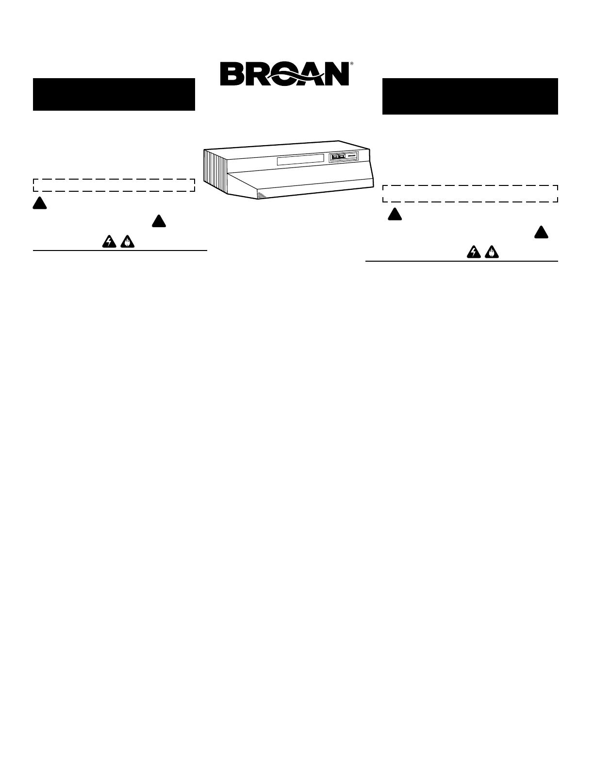
F40000 SERIES
4-WAY CONVERTIBLE
RANGE HOOD
LEA Y CONSERVE
ESTAS INSTRUCCIONES
IMPORTANTE
Para instalación sin ducto:
a) Compra el filtro sin conductos separado.
b) Quite y descarte el conector del regulador/ducto y la
tapa de la rejilla (Véase paso 4) en la Página 2 titulada
“Prepare el extractor.
c) Siga todos los pasos excepto de los pasos dentro las
líneas suspensivas.
Para instalación con ducto:
Siga todos los pasos incluyendo los pasos dentro de
las líneas suspensivas.
ADVERTENCIA
PARA REDUCIR EL RIESGO DE INCENDIO, CHOQUE ELEC-
TRICO, O LESION A PERSONAS, PROCURE LO SIGUIEN-
TE:
1. Utilice esta unidad sólo en la manera prescrita por el fabricante.
Si tiene usted alguna pregunta, comuníquese con el fabricante
a la dirección o el teléfono indicados en la garantía.
2. Antes de limpiar o de poner en servicio la unidad, apague el
interruptor en el panel de servicio, y asegure el panel de
servicio para evitar que se encienda accidentalmente. Cuando
el dispositivo para desconectar el servicio eléctrico no puede
ser cerrado con algún tipo de traba, sujete fuertemente al
panel de servicio, una etiqueta de advertencia prominente.
3. Todo trabajo de instalación y cableado eléctrico debe ser
realizado por personal calificado y de acuerdo con todos los
códigos y normas pertinentes, incluyendo los códigos y
normas relacionados con construcción clasificada para
incendio.
4. Aire suficiente es necesario para facilitar la combustión
adecuada y la salida apropiada de gases por la chimenea de
la unidad y para evitar corrientes de aire invertidas. Siga las
instrucciones y medidas de seguridad del fabricante del equipo
y de las sociedades profesionales de equipos de calentadores
y los reglamentos de seguridad locales.
5. A cortar o perforar la pared o el techo, no dañe el cableado
eléctrico u otros servicios públicos ocultos a la vista.
6. Los abanicos con ducto deberán siempre tener una salida
hacia el exterior.
7. No utilice esta unidad en conjunto con cualquier dispositivo
de control de velocidad de estado sólido.
8. Para reducir el riesgo de incendio, use sólo ductos de metal.
9. Uso con el kit aprobado del la conexión de la cuerda
solamente.
10. Esta unidad se debe instalar con tierra efectiva.
PARA REDUCIR EL RIESGO DE UN INCENDIO POR GRASA
EN EN LA ESTUFA:
1. Nunca deje sin atender las unidades de superficie cuando
tengan ajustes altos. Los reboses pueden provocar humo y
derrames grasosos que se pueden incendiar. Caliente
lentamente el aceite en un ajuste bajo o medio.
2. Siempre ENCIENDA la campana cuando cocine con alta
temperatura o cuando cocine alimentos que se puedan
incendiar.
3. Limpie con frecuencia los ventiladores. No debe permitir que
la grasa se acumule en el ventilador ni en el filtro.
4. Utilice un sartén de tamaño adecuado. Siempre utilice el
utensilio adecuado al tamaño del elemento de superficie.
PARA REDUCIR EL RIESGO DE LESION A PERSONAS RE-
SULTADO DE UN INCENDIO DEBIDO A GRASA ACUMULADA
EN LAS HORNILLAS, PROCURE LO SIGUIENTE:*
1.
AHOGUE LAS LLAMAS con una tapa ajustada o charola de metal,
después apague la hornilla. TENGA CUIDADO A FIN DE EVITAR
QUEMADURAS. Si las llamas no se apagan de inmediato, EVACUE
Y AVISE A LOS BOMBEROS.
2. NO LEVANTE NUNCA UNA SARTEN QUE ESTE EN
LLAMAS - Usted se podrá quemar.
3. NO UTILICE AGUA, incluyendo toallas de cocina mojadas -
puede resultar una explosión de vapor violenta.
4. Utilice un extinguidor SOLAMENTE si:
A. Usted sabe que tiene un extinguidor de clase
ABC y lo sabe utilizar.
B. El incendio es pequeño y contenido dentro del
área donde se inició.
C. Los bomberos han sido avisados.
D. Usted puede combatir el incendio con una salida a
su espalda.
* Basado en las recomendaciones para “Seguridad en la
Cocina” publicadas por la NFPA de los EEUU.
CAMPANA EXTRACTORA
4-WAY CONVERTIBLE
SERIE F40000
!
INTENDED FOR DOMESTIC
COOKING ONLY.
!
!
PREVISTO PARA COCINAR
DOMÉSTICO SOLAMENTE.
!
To register this product visit
www.broan.com
D. You can fight the fire with your back to an exit.
* Based on “Kitchen Fire Safety Tips” published by
NFPA.
CAUTION
!
1. For general ventilating use only. Do not use to exhaust
hazardous or explosive materials and vapors.
2. To avoid motor bearing damage and noisy and/
or unbalanced impellers, keep drywall spray,
construction dust, etc. off power unit.
3. Your hood motor has a thermal overload which will
automatically shut off the motor if it becomes
overheated. The motor will restart when it cools
down. If the motor continues to shut off and restart,
have the hood serviced.
4. For best capture of cooking impurities, your range hood
should be mounted 18-24" above the cooking surface.
5. Please read specification label on product for further
information and requirements.
FIG. 1B
FIG. 1C
FIG. 1D
FIG. 1E
2
6" ROUND DUCT 406
DUCTO REDONDO DE
6" 406
3-1/4" x 10" TO 6"
ROUND DUCT
TRANSITION 411
TRANSICIÓN DE
3-1/4" x 10" A
UN DUCTO
REDONDO
DE 6" 411
WALL CAP 639 OR 649
CASQUETE DE PARED 639 O 649
WALL CAP 639 OR 649
CASQUETE DE PARED
639 O 649
3-1/4" x 10" DUCT 401
DUCTO DE 3-1/4" x 10" 401
ROOF CAP 634 OR 644
CASQUETE DE
TECHO 634 O 644
3-1/4" x 10" DUCT 401
DUCTO DE
3-1/4" x 10" 401
ADJUSTABLE ELBOW 419
CODO AJUSTABLE 419
WALL CAP 641
CASQUETE DE
PARED 641
3-1/4" x 10" TO 6"
ROUND DUCT
TRANSITION 411
TRANSICIÓN DE
3-1/4" x 10" A
UN DUCTO
REDONDO
DE 6" 411
ROOF CAP 634 OR 644
CASQUETE DE TECHO 634 O 644
6" ROUND
DUCT 406
DUCTO
REDONDO
DE 6" 406
PRECAUCION
!
1. Solamente para uso general de ventilación. No utilice para
descargar materiales o vapores riesgosos o explosivos.
2. Para evitar daños al motor y evitar que las navajas del
abanico emitan mucho ruido o estén fuera de balance,
mantenga el motor libre de pelusa, polvo, etc.
3. El motor de su extractor tiene dispositivo de sobrecarga
térmica, al cual automáticamente apagará el motor si
se sobrecalienta. El motor funcionará de nuevo cuando
se enfríe. Si el motor continua apagándose y arrancando,
hágalo componer.
4. Para obtener mejores resultados en la captura de los
vapores de la estufa, el extractor debe montarse a entre
18 y 24 plg. sobre las hornillas de la estufa.
5. Por favor lea la etiqueta con las especificaciones del
equipo para otros requisitos y mayor información.
HERRAMIENTAS Y
MATERIALES QUE SE
REQUIEREN
HERRAMIENTAS
Taladro, eléctrico o trinquete
Broca tipo pala de 1-1/4"
Destornillador de ranura o tipo phillips
Pinzas o tenazas
Medidor de cinta o regla y lápiz
Para instalaciones con ducto SOLAMENTE:
Sierra tipo sable o sierra para tabiques
Alicate para cortar
MATERIALES
Suministros y alambre eléctrico del tipo que cumplen
con los códigos locales
Casquete de techo o pared
Cemento o pega de techa o material de calafatear
o rellenar
Ductos y cinta aislante para ductos
Para instalación en gabinetes de cocina con la parte infe-
rior ahuecada solamente:
Dos tiras de madera 1" x 2" x 12" (largo aproximado)
(cómpreselas localmente)
Cuatro tornillos para madera de cabeza plana de 1-1/4"
de largo (cómpreselas localmente) para sujetar las tiras
de madera a la parte inferior de gabinete
PLANIFICANDO LA
INSTALACION DE LOS
DUCTOS
Comience el trabajo de los ductos decidiendo el camino
que el ducto tomará entre el extractor y la parte exterior
de la casa. Para mejor rendimiento, use el camino de ducto
más corto posible y un mínimo de codos. Se muestran
varias elecciones - FIGS. 1A - 1E.
En situaciones de paso del ducto más complejas, el ex-
tractor con conexión para ducto rectangular puede
convertirse en conexión redonda usando una transición.
FIG. 1A. Pasando el ducto directamente a través de la
pared (para los extractores que están instalados en una
pared exterior). Se muestran dos maneras de pasar el
ducto a través de la pared exterior. Si se usa un casquete
de pared directamente en la parte de atrás del extractor
hay que asegurarse que el regulador en el conector entre
ducto y regulador en el extractor, y el regulador en el
casquete de pared no interfieran el uno con el otro cuando
el extractor esté operando. Esto podría resultar en paso
de aire inadecuado o corrientes invertidas. Si esta
condición existe, quite la hoja instalada en el regulador
del extractor. A veces cuando se usa un casquete de pared
es más fácil pasar el ducto verticalmente y usar un codo
como se muestra en FIG. 1B.
FIG. 1C. Haciendo un ducto directamente al techo usando
un ducto rectangular de 3-1/4" x 10" (para instalaciones
en un piso solamente).
FIG. 1D. Instalando un ducto entre las vigas del techo
(para instalaciones en más de un piso) o a través del
espacio de sofito arriba de los gabinetes (cuando el sofito
está conectado a una pared exterior).
FIG. 1E. Directamente hacia el techo usando transición
de 3-1/4” x 10” a un ducto redondo de 6” y ducto redondo
de 6" (para instalaciones de un piso).
FIG. 1F. Directamente hacia el techo usando ducto
redondo de 7" (para instalaciones de un piso).
TOOLS AND
MATERIALS REQUIRED
TOOLS
Drill, electric or ratchet drive
1-1/4" Spade bit
Common head and phillips head screwdriver
Pliers
Tape measure or ruler and pencil
For Ducted Installations ONLY:
Saber saw or drywall saw
Metal snips
MATERIALS
Electrical wiring and supplies of type to comply
with local codesFor Ducted Installations Only:
Roof or wall cap
Roof cement or caulk
Duct and duct tape
For Installation on Kitchen Cabinets with Recessed
Bottoms Only:
Two 1" x 2" x 12" (approximate length) wood strips
(purchase locally)
Four 1-1/4" long flat head wood screws (purchase
locally) to fasten strips to cabinet bottom
PLANNING DUCTWORK
INSTALLATION
Begin planning ductwork by deciding where the duct
will run between the range hood and the outside. For
best performance, use the shortest possible duct run
and a minimum number of elbows. There are several
choices shown - FIGS. 1A - 1E.
In more complex ducting situations, a 3-1/4" rectan-
gular ducting range hood can be converted to a round
duct by means of a transition.
FIG. 1A. Ducting directly through the wall (for range
hoods mounted on an exterior wall). Shown are two
ways to duct through an outside wall. If a wall cap is
used directly off the back of the hood, special care
must be taken to make sure that the damper in the
damper/duct connector on the hood and damper in
the wall cap do not interfere with each other when the
hood is operating. This could result in either inad-
equate air delivery or back drafts. If this condition does
exist, remove the hood damper flap. Sometimes when
using a wall cap it is easier to duct vertically and then
use an elbow as shown in FIG. 1B.
FIG. 1C. Ducting straight up through the roof using
3-1/4" x 10" rectangular duct. (For single story in-
stallations.)
FIG. 1D. Ducting between the ceiling joists (for multi-
story installations) or through the soffit space above
the cabinets (where the soffit connects to an outside
wall).
FIG. 1E. Straight up through the roof using 3-1/4” x
10” to 6” round duct transition and 6" round duct (for
single-story installations).
FIG. 1F. Straight up through the roof using 7" round
duct (for single-story installations).
FIG. 1A
7" ROUND DUCT 407
DUCTO REDONDO
DE 7” 407
MODEL BP87
DAMPER
REGISTRO
DE TIRO
MODELO BP87
ROOF CAP 634
CASQUETE DE
TECHO 634
FIG. 1F
3
FIG. 2
FIG. 5
FIG. 6
FIG. 7
CUT STRIPS TO FIT
CORTE LAS TIRAS PARA
QUE QUEPAN
CENTER LINE
LINEA CENTRICA
WIDTH OF
RANGE HOOD
ANCHO DEL
EXTRACTOR
ELECTRICAL WIRING OPENING
ABERTURA PARA EL
CABLEADO ELECTRICO
PREPARANDO EL EXTRACTOR
1. Desempaque el extractor y revise el contenido de la
caja. Usted debe de encontrar:
1 - Filtro de aluminio
1 - Conector de ducto/regulador de 3-1/4" x 10"
(montado dentro del extractor para embarque
solamente) (Guarde los tornillos para el monta-
je.)
1 - Placa del conducto redondo de 7” (montado en
del extractor) (no se muestra) (Guarde los torni-
llos para el montaje.)
2. Quite la placa del conducto redondo de 7” de la parte
superior de la campana. Colóquela aparte, con los
tornillos de montaje.
3. Quite la cubierta de la caja de cableado. Bajo la tapa
encontrará:
1 - Una bolsa de plástico que contiene herrajes
sueltos para instalación
Para instalaciones sin ducto SOLAMENTE:
4. Para instalaciones sin ducto, quite la tapa de la reji-
llas de la parte frontal del extractor. (FIG. 3)
NOTA
Las rejillas que se encuentran al frente de la campana
deben estar abiertas y visibles para que la campana
funcione sin conducto.
5. Quite la tapa de quitar golpeando eléctrica de arriba
o atrás dependiendo en donde entra el cableado al
extractor de la pared o del gabinete. (FIG. 4)
INSTALACION CON DUCTO SOLAMENTE
NOTA
La cubierta de las rejillas se debe instalar como se
muestra en la figura 3 para que funcione con el
conducto.
6. Quite la placa de quitar golpeando en el extractor
insertando un destornillador en el filo y rompiendo
las conexiones que lo sostienen al extractor. Es
posible que tenga que golpear el destornillador con
un martillo para romper estas uniones. Pele la tapa
de quitar golpeando hacia atrás con una tenaza.
(FIG. 5)
7. Junte el conector del regulador/ducto sobre la aber-
tura y sujételo en su sitio con tornillos negros de
metal para lámina. (FIG. 6)
Los pasadores de bisagra y el conector del regula-
dor/ducto deben de estar hacia la parte de arriba
del extractor para pasar el ducto a través de la pa-
red o hacia la parte de atrás del extractor para pa-
sar el ducto a través de gabinete encima del
extractor. Selle la unión entre el conector regula-
dor/ducto con cinta de ducto.
8. Sólo para descargas con conducto redondo de
7”: Vuelva a instalar la placa del conducto redondo
de 7” que quitó en el paso 2 de la sección “PREPA-
RANDO EL EXTRACTOR.” Para obtener un mejor
rendimiento, alinee la placa del conducto redondo
de 17.8 cm (7”) con la abertura redonda de 17.8
cm (7”) de la campana. Monte la placa del conduc-
to a la campana con dos tornillos desde la placa
del conducto y con dos tornillos desde el tiro de 8.3
x 25.4 cm (3 ¼” x 10”). Instale un regulador de tiro
redondo de 7” (se compra por separado). La aleta
del regulador se debe abrir libremente en dirección
del flujo de aire (en sentido contrario a la campana
de la estufa).
PREPARANDO LA UBICACION
DE LA INSTALACION
NOTA
MONTE EL EXTRACTOR DE MANERA QUE LA PARTE
INFERIOR ESTÉ 18"-24" ENCIMA DE LA SUPERFICIE
DE LA COCINA. LA PARTE SUPERIOR DEL FRENTE
DEL EXTRACTOR DEBE DE ESTAR A RAS CON EL
FRENTE DEL ARMAZÓN DEL GABINETE.
SI LA DISTANCIA ENTRE LA PARED Y LA PARTE FRON-
TAL DEL ARMAZÓN DEL GABINETE ES MÁS DE 12"
HABRÁ UN ESPACIO ENTRE LA PARTE DE ATRÁS DEL
EXTRACTOR Y LA PARED. ESTO ES NORMAL.
OMITA PASO 7 si el extractor estará instalado debajo de
un gabinete con la parte inferior plana.
9. (Para instalación en gabinetes ahuecados solamente)
Sujete una tira de madera a cada lado de la parte
inferior ahuecada debajo del gabinete. (Use dos tiras
de madera de 1" x 2" cortadas al largo necesario.) Si
el ahuecamiento es más de 1" use tiras más gruesas.
Sujete las tiras con tornillos de 1-1/4" a una distancia
de más o menos 3" del extremo. Véase FIG. 7.
FIG. 3
DUCT OPENINGS
ABERTURA PARA
EL DUCTO
PREPARING THE
RANGE HOOD
1. Unpack hood and check contents. You should
receive:
1 - Aluminum Filter
1 - 3-1/4" x 10" Damper/Duct Connector (mounted
inside of hood for shipping only) (Save screws
for mounting.)
1 - 7” Round Duct Plate (mounted on top of hood)
(not shown) (Save screws for mounting.)
2. Remove 7” round duct plate from top of hood.
Set duct plate aside - with mounting screws.
3. Remove wiring box cover. Under cover find:
1 - Plastic Bag containing loose mounting hardware
PREPARING THE
INSTALLATION LOCATION
NOTE
MOUNT HOOD SO THAT BOTTOM OF HOOD IS
18"-24" ABOVE COOKING SURFACE. TOP
FRONT EDGE OF HOOD SHOULD BE FLUSH
WITH FRONT OF CABINET FRAME.
IF DISTANCE BETWEEN WALL AND FRONT OF
CABINET FRAME IS MORE THAN 12" THERE
WILL BE A SPACE BETWEEN BACK OF HOOD
AND WALL. THIS IS NORMAL.
OMIT STEP 9 if range hood will be installed under
cabinets with flush bottom.
9. (For installation on recessed bottom cabinets
only) Attach a wood filler strip at each side of
recessed area under cabinet. (Use two 1" x 2"
strips cut to length.) If recess is more than 1" use
thicker strips. Attach strips with 1-1/4" screws
about 3" from each end. See FIG. 7.
10.Measure and mark the following (FIGS. 7 & 8):
a) Electrical line opening
b) Duct opening
11.Drill four pilot holes in corners of marked duct
opening as shown and cut opening with saber
saw or keyhole saw.
12.Use 1-1/4" drill bit to drill opening for electrical
connection in wall or cabinet.
13.Hold hood up against cabinet bottom and trace
keyhole slots onto cabinet bottom of filler strips.
14.Screw the four supplied 7/8" wood screws for
mounting the hood into the exact center of the
narrow end of the keyhole slots marked under-
neath the cabinet. Allow 3/8" of the screws to
project, so the hood can be fitted into place.
FIG. 4
WIRING BOX COVER
TAPA DE LA CAJA DE
CABLEADO
KEYHOLE SLOTS
RANURAS EN FORMA
DE HUECO DE
CERRADURA
DAMPER/DUCT CONNECTOR
CONECTOR AL REGULADOR/DUCTO
ALUMINUM FILTER
FILTRO DE ALUMINIO
For Ductfree Installations Only:
4. For ductfree installation, remove louver cover from
front (or inside) of hood. (FIG. 3)
NOTE
Louvers on front of hood must be open and
visible for hood to function in ductfree mode.
5. Remove either top or rear electrical knockout de-
pending upon whether wiring will enter hood from
wall or cabinet. (FIG. 4)
DUCTED INSTALLATION ONLY
NOTE
Louver cover must be installed as shown in
Figure 3 to function in ducted mode.
6. Remove appropriate duct knockout on hood by
inserting screwdriver into edge of knockout and
breaking tabs holding knockout to hood. You may
have to tap screwdriver with hammer to break tabs.
Peel knockout back with pliers. (FIG. 5)
7. Fit damper/duct connector over opening and secure
in place with black sheet metal screws. (FIG. 6)
Hinge pins and damper/duct connector should be
toward top of hood for ducting through wall or to-
ward back of hood for ducting through cabinet
above hood. Seal joint between damper/duct con-
nector and hood with duct tape.
8. 7” round ducted discharge only: Re-install 7”
round duct plate removed in Step #2 under “PRE-
PARING THE RANGE HOOD” section. For best
performance, line up the 7” round duct plate
with the 7” round opening on hood. Mount duct
plate to hood with 2 screws from duct plate and 2
screws from 3¼” x 10” damper. Install a 7” round
damper (purchase separately). Damper flap must
open freely in direction of air flow (away from range
hood).
4
INSTALANDO LOS
DUCTOS
NOTESE
ESTAS INSTRUCCIONES SEGUIRÁN LOS PLANES
HECHOS EN LA PÁGINA 2. COMIENCE EN LA
PARTE EXTERIOR Y TRAIGA EL DUCTO HACIA
EL EXTRACTOR.
PARA EL MEJOR RENDIMIENTO DE SU EXTRAC-
TOR, USE EL CAMINO MÁS CORTO DE DUCTO Y
UN MÍNIMO DE CODOS.
NUNCA DESCARGUE EL AIRE DEL EXTRACTOR
EN EL ESPACIO DE LA BUHARDILLA PORQUE
UNA ACUMULACIÓN DE GRASA PODRÍA CAUSAR
UN INCENDIO.
USE SOLAMENTE DUCTOS DE METAL (NO USE
DUCTOS DE PLÁSTICO). ENSÁMBLELOS BIEN DE
MANERA QUE EN CASO DE QUE HUBIESE UN
INCENDIO CAUSADO POR GRASA, EL INCENDIO
SE QUEDARÁ CONTENIDO DENTRO DE LOS
DUCTOS DE METAL.
ES UNA BUENA PRÁCTICA EL PONER CINTA EN
TODAS LAS CONEXIONES DEL DUCTO
HACIÉNDOLOS NO SOLAMENTE SEGUROS SI NO
TAMBIÉN A PRUEBA DE ESCAPE DE AIRE.
15.Siga las direcciones apropiadas abajo para el tipo
de ductos que esté instalando:
CASQUETES DE PARED (FIG. 9)
Use una sierra sable para cortar un hueco ligeramente
más grande que el diámetro del ducto de manera que
el ducto se alinee más fácilmente con el extractor.
Instale tiras de sostén en las paredes exteriores que
estén acabadas con superficie exterior de madera,
aluminio o vinilo. Ensamble los ductos y ponga cinta
en todas las uniones. Traiga los ductos de afuera hacia
al extractor. Sujete el casquete de pared a la última
sección de ducto y clave el casquete a la pared. Selle
alrededor de la ceja del casquete con un compuesto
para rellenar. Asegúrese que hay suficiente ducto que
entra a la cocina de manera que el ducto sobrepasará
y entrará dentro el conector de regulador/ducto por lo
menos por 3/4" cuando esté el ducto instalado.
CASQUETES DEL TECHO
Corte un hueco en el techo más grande que el diámetro
del ducto de manera que el ducto se alineará más
fácilmente con el extractor. Recorte el tejado (tablillas
de tejado) alrededor de hueco de manera que quepan
apretadamente alrededor de casquete cuando éste
instalado. Ensamble los ductos y ponga cinta aislante
en todas las uniones. Traiga el ducto hacia abajo, al
extractor. Recorte el ducto paralelo a la inclinación del
techo, dejando 3/4" de ducto que se proyecte más
arriba de techo. Selle la abertura alrededor de ducto
con cemento de techo.
Instale el casquete insertando el filo de atrás de la
ceja del casquete debajo de las tablillas del tejado.
Selle alrededor del casquete con cemento de techo y
selle todas las cabezas de clavos y tablillas que fueron
cortadas o levantadas.
Asegúrese que haya suficiente ducto que se proyecte
dentro la cocina de manera que el ducto sobrepase al
conector de regulador/ducto por 3/4" cuando el extrac-
tor esté en su sitio.
FIG. 8
FRONT OF CABINET
PARTE FRONTAL DEL
GABINETE
VERTICAL DUCTING AND WIRING
(Through Cabinet Bottom)
DUCTOS Y ALAMBRES PARA CONEXION VERTICAL (A
través de la parte inferior del gabinete)
CABINET BOTTOM
PARTE INFERIOR DEL
GABINETE
BACK WALL
PARED TRASERA
FIG. 9
WALL CAP
TAPA DE PARED
INSTALLING THE
DUCTWORK
NOTE
THESE INSTRUCTIONS WILL FOLLOW THE
PLANS MADE ON PAGE 2. START AT THE EX-
TERIOR AND RUN THE DUCT BACK TO THE
RANGE HOOD.
FOR BEST PERFORMANCE OF YOUR RANGE
HOOD, USE THE SHORTEST POSSIBLE DUCT
RUN AND A MINIMUM NUMBER OF ELBOWS.
NEVER VENT A RANGE HOOD INTO AN AT-
TIC SPACE BECAUSE A BUILDUP OF
GREASE WILL BECOME A FIRE HAZARD.
USE ONLY METAL DUCTWORK (DO NOT USE
PLASTIC DUCT). ASSEMBLE SECURELY SO
THAT IN CASE OF A GREASE FIRE ON THE
RANGE, THE FIRE WILL BE CONTAINED IN-
SIDE METAL DUCT WORK.
IT IS A GOOD PRACTICE TO TAPE ALL DUCT
CONNECTIONS, MAKING THEM BOTH SE-
CURE AND AIR TIGHT.
15.Follow appropriate directions below for type of
duct work you are installing:
WALL CAPS (FIG. 9)
Use a saber saw to cut a hole slightly larger than
duct so duct will line up easily with hood. Install
casing strips on outside walls finished in siding.
Assemble the duct work and tape all joints. Run
duct work back to hood. Fasten wall cap to last
section of duct and nail or screw cap to wall. Seal
all around flange on wall cap with caulking com-
pound. Make sure that enough duct runs into the
room so that the duct will overlap the damper/duct
connector by 3/4" when the hood is installed.
ROOF CAPS
Cut hole in roof slightly larger than duct so duct
will line up easily with hood. Trim shingles around
hole so that they will fit snugly around hood of cap
when cap is installed. Assemble the duct work and
tape all joints. Run the duct work down to hood.
Trim duct parallel to roof pitch, leaving 3/4" of duct
projecting above roof. Seal all around duct with
roof cement.
Install roof cap, inserting back edge of cap under
shingles. Seal around cap with roof cement and
seal all nail heads and shingles which were cut or
lifted.
Make sure that enough duct runs into the room so
that the duct will overlap the damper/duct connec-
tor by 3/4" when the hood is put into place.
3/8"
3-7/8"
HORIZONTAL DUCTING AND
WIRING (Through Wall)
DUCTOS Y ALAMBRES PARA CONEXION
HORIZONTAL (A través de la pared)
5-1/4"
5-1/4"
7-1/2"
1/8"
3/4"
1-1/2"
1-1/2"
9"
10-5/8"
6-7/8"
7-1/2"
5-1/4"
5-1/4"
9-7/8"
9"
CABINET FRONT / FRENTE DEL GABINETE
CABINET BOTTOM
FONDO DEL GABINETE
7½"
2"
5"
WOOD SHIMS
(recessed-bottom cabinets only)
CUÑAS DE MADERA
(sólo gabinetes de fondo empotrado)
ELECTRICAL ACCESS HOLE
(in cabinet bottom)
ORIFICIO DE ACCESO PARA
LOS CABLES ELÉCTRICOS
(en el fondo del gabinete)
8" DIA. ACCESS HOLE
ORIFICIO DE ACCESO
8" DE DIÁ.
3-1/4” x 10” DUCT
DUCTO DE 3-1/4” x 10”
7” ROUND DUCT
DUCTO REDONDO DE 7”
PREPARANDO LA UBICACION
DE LA INSTALACION (CONT.)
10.Mida y marque lo siguiente (FIG. 7 & 8):
a) Abertura para la línea eléctrica
b) Abertura para el ducto
11.Perfore cuatro huecos pilotos en las esquinas ya
marcadas de la abertura para el ducto como se
muestra y luego corte un abertura con un serrucho
sable o un serrucho para cerradura.
12.Usese una broca de 1-1/4" para perforar una abertura
para la conexión eléctrica en la pared o gabinete.
13.Sostenga al extractor debajo de la parte inferior del
gabinete y trace las ranuras en forma de hueco de
cerradura en la parte inferior del gabinete donde se
instalarán las tiras de madera.
14.Atornille cuatro de los tornillos de madera de 7/8" para
montar el extractor en el centro exacto de la parte
estrecha de la ranuras en forma de cerradura que se
marcaron debajo del gabinete. Permita que 3/8" de
los tornillos queden afuera, para que luego pueda
instalarse al extractor en su sitio.
USE AND CARE
SWITCHES
The fan and light are each controlled by a rocker
switch. The light switch has two positions, “ON” and
“OFF”. The fan switch has three positions - “HIGH”,
“LOW” and “OFF”. ( “OFF” is the middle position.)
CLEANING
Finish Keep your range hood clean using a mild de-
tergent suitable for painted surfaces.
Aluminum Filters should be cleaned frequently with
a detergent solution to avoid grease build up. They
are also dishwasher safe.
INSTALLING THE
RANGE HOOD
16.Bring electrical cable through access hole drilled
in wall or bottom of cabinet. Provide 6" wire leads
and install proper connector for type of cable be-
ing used. Remove lock nut from connector and
let prepared cable project through cabinet or wall
opening so it is ready for installation into range
hood. (FIG. 10)
17.Position hood in place so that:
a) Electrical line is routed through appropriate
knockout opening. This step will have to be
accomplished while positioning hood. (FIG. 13)
b) Large part of keyhole mounting slots on hood
fit onto hood mounting screws projecting from
bottom of cabinet. (FIG. 11)
c) Damper/duct connector slides into duct work
in wall or cabinet.
18.Adjust hood so the front of hood is flush with cabinet
front.
19.Tighten the four hood mounting screws securely.
20.Install locknut on electrical connector and tighten
securely.
21.Make electrical connection using wire nuts to con-
nect white wire to white, black wire to black.
Ground hood to prepared hole using green ground
screw provided. (FIG. 12)
22. Replace wiring box cover and screw. Make sure
that all wiring is safely contained inside.
NOTE
For Ductfree Installations Only:
Install both filters. Make sure that ductfree filter
(purchase separately) is next to fan assembly with
blue side next to blade. Aluminum filter should be
facing out.
FILTER REMOVAL
Filters on the F40000 series hood are removed by
turning filter clip to the side and lifting filter or filters
out. In ducted version, turn filter retaining clip to one
side and place aluminum filter under embossed re-
taining tabs on back of fan housing. Turn filter clip so
that the low end of clip holds single filter firmly in place.
(FIG. 13)
In ductfree version, place both aluminum and ductfree
filter under tabs on back of fan housing. Turn filter re-
taining clip so that high end holds both filters firmly in
place. Make sure ductfree filter is next to fan assem-
bly, with blue side next to fan blade, and aluminum
filter is facing out.
NOTE: Make sure that arrows on filter retaining clip
point toward back and front of hood.
LIGHT BULB REPLACEMENT
Light bulb (not supplied with hood) should be 75 watts
maximum. The lens covering bulb is removed by press-
ing the two extending tabs together until they release
from the retaining slots. (FIG. 14)
FAN ASSEMBLY REMOVAL
Be sure power is disconnected. Remove filters. Re-
move the two screws holding the motor bracket to the
range hood and unplug the fan assembly. Be careful
not to allow fan assembly to drop when the screws
are removed. (FIG. 15).
5
CONNECTOR
CONECTOR
FIG. 12
FIG. 13
NON-DUCTED FILTER (SOLD SEPARATELY)
FILTRO QUE NO REQUIERE DUCTO
(VENDIDO SEPARADAMENTE)
ALUMINUM FILTER
FILTRO DE ALUMINIO
FILTER RETAINING CLIP
GRAMPA RETENTORA
DEL FILTRO
FIG. 14
LIGHT LENS
VIDRIO QUE CUBRE EL
BOMBILLO
SOCKET
BOQUILLA
FIG. 15
SCREWS
TORNILLOS
ELECTRICAL LINE
LINEA ELECTRICA
FIG. 11
FIG. 10
INSTALANDO EL EXTRACTOR
16.Pase el cableado eléctrico a través del hueco de acceso
perforado en la pared o la parte inferior del gabinete.
Suministre alambres de por lo menos 6" e instale el
conector apropiado para el tipo de cable que está
usándose. Quite la tuerca de traba del conector y deje
que el cable preparado se proyecte a través del
gabinete o abertura de pared de manera que esté listo
para instalarse dentro del extractor. (FIG. 10)
17.Posicione al extractor en su sitio de manera que:
a) La línea eléctrica pase a través de la abertura de
quitar golpeando. Este paso se puede conseguir
mientras se posiciona el extractor. (FIG. 13)
b) La parte más grande de las ranuras en forma de
hueco de cerradura en el extractor caben sobre
los tornillos montantes que están proyectándose
de la parte inferior del gabinete. (FIG. 11)
c) El conector para el regulador/ducto se desliza
sobre los ductos en la pared o gabinete.
18.Ajuste el extractor de manera que la parte frontal del
extractor esté a ras con la parte frontal del gabinete.
19.Ajuste los cuatro tornillos para madera apretándolos
firmemente.
20.Instale una tuerca de traba al conector eléctrico y
apriételo.
21.Haga la conexión eléctrica usando tuercas de alambre
para conectar el alambre blanco a blanco, negro a negro.
Conecte el extractor a tierra a través del hueco preparado,
usando el tornillo verde suministrado. (FIG. 12)
22.Ponga la tapa de la caja del cableado y atorníllela.
Asegúrese que todo el cableado esté dentro de la caja.
NOTA
Para instalación sin ducto solamente:
Instale ambos filtros. Asegúrese que el filtro (compra
separado) que no necesita ducto esté más cerca del
emsamblaje del ventilador con el lado azul hacia las
aspas. El filtro de aluminio debe de estar en la parte
exterior.
USO Y MANTENIMIENTO
LOS INTERRUPTORES
El abanico y el foco están controlados individualmente
por un interruptor balancín. El interruptor del foco tiene
dos posiciones, ENCENDIDO (“ON”) y APAGADO (“OFF”).
El interruptor del abanico tiene tres posiciones - ALTA
(“HIGH”), BAJA (“LOW”) y APAGADO (“OFF”). (El
interruptor para APAGADO está en la posición de en
medio.)
LIMPIEZA
Acabado. Mantenga el extractor limpio usando un
detergente suave apropiado para superficies pintadas.
Filtros aluminio. Deberían limpiarse frecuentemente en
una solución de detergente para evitar la acumulación de
grasa. Estos pueden ser lavados en la lavadora de platos.
QUITANDO EL FILTRO
Los filtros en los extractores de la serie F40000 se sacan
moviendo la grampa del filtro a un lado y levantando el
filtro o los filtros hacia afuera. En la versión con ductos,
dé la vuelta a la grampa retentora del filtro a un lado y
ponga el filtro de aluminio debajo de las uñas resaltadas
retentoras en la parte de atrás de bastidor del ventilador
o abanico. De la vuelta a la grampa del filtro de manera
que el extremo de abajo de la grampa, sostiene un solo
filtro firmemente en su sitio. (FIG. 13)
En la versión que no requiere ducto ponga ambos, el filtro
de aluminio y el filtro que no requiere ducto bajo las
grampas en la parte de atrás del bastidor del ventilador.
Dé la vuelta a los sostenes retentores de manera que el
extremo alto sostiene ambos filtros firmemente en su sitio.
Asegúrese que el filtro que no requiere ducto esté más
cerca al ensamblaje del ventilador, con el lado azul a lado
de las aspas del ventilador, y el filtro de aluminio quede
hacia afuera.
NOTESE: Asegúrese que las flechas en el punto donde
se pone las grampa retentoras apunten hacia atrás, a la
parte frontal del extractor.
REEMPLAZO DEL BOMBILLO DE LUZ
El bombillo de luz (que no viene con el extractor) debería de
ser de un máximo de 75 vatios. El vidrio lente que cubre el
bombillo se quita pellizcado los dos sostenes que se extienden,
hasta que se salen de sus ranuras retentoras. (FIG. 14)
COMO QUITAR EL ENSAMBLAJE DEL VENTILADOR
Asegúrese que la potencia eléctrica esté desconectada.
Quite los filtros. Quite los dos tornillos que sostienen el
sostén del motor al extractor y desenchufe el ensamblaje
de ventilador. Tenga cuidado que no permita que el
ensamblaje del ventilador se caiga cuando se quiten los
tornillos. (FIG. 15)
BLACK WIRES
ALAMBRES NEGROS
GROUNDING BRACKET
SOSTEN PARA
CONECTAR A TIERRA
STAR LOCKNUT
TUERCA TRABANTE
EN FORMA DE
ESTRELLA
GREEN GROUND SCREW
TORNILLO VERDE PARA TIERRA
GROUND WIRE (BARE OR
GREEN WIRE)
ALAMBRE DE TIERRA
(ALAMBRE DESNUDO O
VERDE)
WHITE WIRES
ALAMBRES BLANCOS
COMO EVITAR QUE OCURRA UN INCENDIO
DEBIDO A LA GRASA QUE SE ACUMULA EN UN
EXTRACTOR COMUN
• Su extractor proporciona una barrera protectora
entre la superficie para cocinar y los gabinetes.
• Mantenga el abanico, los filtros y las superficies
donde se acumula la grasa LIMPIAS conforme a
las instrucciones.
ENCIENDA siempre el extractor cuando esté
cocinando a fuego alto para mantener el area para
cocinar y el extractor limpios.
Utilice las hornillas de fuego alto solamente cuando
sea necesario.
No deje las hornillas de la estufa sin atención
cuando esté cocinando. El vapor o el aceite
que salpique puede ocasionar un incendio
o acumulación de humo.
Siempre utilice los utensilios del tamaño adecuado.
Si está preparando alimentos flameados, como las
Cerezas a la Jubilee, ENCIENDA siempre el ex-
tractor en ALTO para evitar que el calor pueda
causar algún daño o un incendio.
COMO EXTINGUIR UN INCENDIO EN UN EXTRAC-
TOR COMUN
No levante nunca una sartén que esté en llamas.
Si se le cae, las llamas se pueden extender
rapidamente.
¡
NO UTILICE AGUA PARA APAGARLO! Puede
ocasionar una explosión de vapor. Las toallas de
cocina mojadas también son peligrosas.
• Ahogue las llamas con una tapa ajustada o una
charola.
• Las llamas provocadas por la grasa también se
pueden apagar con bicarbonato de sodio o un
extinguidor químico.
Apague las hornillas - si puede hacerlo sin
quemarse.
HOW TO AVOID A COMMON RANGE-TOP
GREASE FIRE
Your range hood provides a protective barrier
between the cooking surface and the cabinets.
• Keep fan, filters and grease laden surfaces
CLEAN according to instructions.
Always turn hood ON when cooking at high heat
to keep the cooking area and the hood cooler.
Use high heat settings only when necessary.
Never leave cooking surface unattended. Boil-
over causes smoking and greasy spillovers that
may ignite.
Always use adequate-sized utensils.
If preparing flaming foods, such as Cherries Ju-
bilee, always turn hood ON to HIGH to prevent
a high heat situation which can cause damage
or fire.
HOW TO EXTINGUISH A COMMON RANGE-TOP
GREASE FIRE
Never pick up a flaming pan. If dropped, flames
can spread quickly.
DO NOT USE WATER! A violent steam explo-
sion may result. Wet dishcloths or towels are
also dangerous.
Smother flames with a close fitting lid, cookie
sheet or metal tray.
Flaming grease can also be extinguished with
baking soda or a multi-purpose dry chemical
extinguisher.
Turn off surface units - if you can do so without
getting burned.
6
GARANTIA BROAN LIMITADA POR UN AÑO
Broan-NuTone garantiza al consumidor comprador original de sus productos que dichos productos carecerán
de defectos en materiales o en mano de obra por un período de un año a partir de la fecha original de compra.
NO EXISTEN OTRAS GARANTIAS, EXPLICITAS O IMPLICITAS, INCLUYENDO, PERO NO LIMITADAS A,
GARANTIAS IMPLICITAS DE COMERCIALIZACION O APTITUD PARA UN PROPOSITO PARTICULAR.
Durante el período de un año, y a su propio criterio, Broan-NuTone reparará o reemplazará, sin costo alguno
cualquier producto o pieza que se encuentre defectuosa bajo condiciones normales de servicio y uso.
ESTA GARANTIA NO SE APLICA A TUBOS Y ARRANCADORES DE LAMPARAS FLUORESCENTES. Esta
garantía no cubre (a) mantenimiento y servicio normales o (b) cualquier producto o piezas que hayan sido
utilizadas de forma errónea, negligente, que hayan causado un accidente, o que hayan sido reparadas o
mantenidas inapropiadamente (por otras compañías que no sean Broan-NuTone), instalación defectuosa, o
instalación contraria a las instrucciones de instalación recomendadas.
La duración de cualquier garantía implícita se limita a un período de un año como se especifica en la garantía
expresa. Algunos estados no permiten limitaciones en cuanto al tiempo de expiración de una garantía implícita,
por lo que la limitación antes mencionada puede no aplicarse a usted.
LA OBLIGACION DE BROAN-NUTONE DE REPARAR O REEMPLAZAR, SIGUIENDO EL CRITERIO DE BROAN-
NUTONE, DEBERA SER EL UNICO Y EXCLUSIVO RECURSO LEGAL DEL COMPRADOR BAJO ESTA
GARANTIA. BROAN-NUTONE NO SERA RESPONSABLE POR DAÑOS INCIDENTALES, CONSIGUIENTES,
O POR DAÑOS ESPECIALES QUE SURJAN A RAIZ DEL USO O DESEMPEÑO DEL PRODUCTO.
Algunos estados no permiten la exclusión o limitación de daños incidentales o consiguientes, por lo que la
limitación antes mencionada puede no aplicarse a usted. Esta garantía le proporciona derechos legales
específicos, y usted puede también tener otros derechos, los cuales varían de estado a estado. Esta garantía
reemplaza todas las garantías anteriores.
Para calificar en la garantía de servicio, usted debe (a) notificar a Broan-NuTone al domicilio que se menciona
abajo o al teléfono:1-800-637-1453, (b) dar el número del modelo y la identificación de la pieza, y (c) describir
la naturaleza de cualquier defecto en el producto o pieza. En el momento de solicitar servicio cubierto por la
garantía, usted debe de presentar evidencia de la fecha original de compra.
Broan-NuTone LLC
926 West State Street,
Hartford, WI 53027 E.U.A.
BROAN-NUTONE ONE YEAR LIMITED WARRANTY
Broan-NuTone warrants to the original consumer purchaser of its products that such products will be
free from defects in materials or workmanship for a period of one year from the date of original
purchase. THERE ARE NO OTHER WARRANTIES, EXPRESS OR IMPLIED, INCLUDING, BUT
NOT LIMITED TO, IMPLIED WARRANTIES OF MERCHANTABILITY OR FITNESS FOR A PAR-
TICULAR PURPOSE.
During this one-year period, Broan-NuTone will, at its option, repair or replace, without charge, any
product or part which is found to be defective under normal use and service.
THIS WARRANTY DOES NOT EXTEND TO FLUORESCENT LAMP STARTERS AND TUBES.
This warranty does not cover (a) normal maintenance and service or (b) any products or parts which
have been subject to misuse, negligence, accident, improper maintenance or repair (other than by
Broan-NuTone), faulty installation or installation contrary to recommended installation instructions.
The duration of an implied warranty is limited to the one-year period as specified for the express
warranty. Some states do not allow limitation on how long an implied warranty lasts, so the above
limitation may not apply to you.
BROAN-NUTONE’S OBLIGATION TO REPAIR OR REPLACE, AT BROAN-NUTONE’S OPTION,
SHALL BE THE PURCHASER’S SOLE AND EXCLUSIVE REMEDY UNDER THIS WARRANTY.
BROAN-NUTONE SHALL NOT BE LIABLE FOR INCIDENTAL, CONSEQUENTIAL OR SPECIAL
DAMAGES ARISING OUT OF OR IN CONNECTION WITH PRODUCT USE OR PERFORMANCE.
Some states do not allow the exclusion or limitation of incidental or consequential damages, so the
above limitation may not apply to you.
This warranty gives you specific legal rights, and you may also have other rights, which vary from
state to state. This warranty supersedes all prior warranties.
To qualify for warranty service, you must (a) notify Broan-NuTone at the address stated below or
telephone: 1-800-637-1453, (b) give the model number and part identification and (c) describe the
nature of any defect in the product or part. At the time of requesting warranty service, you must
present evidence of the original purchase date.
Broan-NuTone LLC
926 West State Street,
Hartford, WI 53027
7
PARTES DE SERVICIO
SERIE F40000 CAMPANA EXTRACTORA
SERVICE PARTS
F40000 SERIES RANGE HOOD
KEY NO. PART NO.
NO. CODIGO NO. PIEZ DESCRIPTION DESCRIPCION
1 98006621 Outlet Box Cover Cubierta de la caja de la toma de corriente
2 99170245 #8 x 3/8 Sheet Metal Screw* Tornillos de metal para lámina #8 x 3/8*
3 99270987 Bulb Holder with Wires Contenedor del bulbo con cableado
4 99110437 Light Lens Cubierta protectora del foco
5 97011217 Screw/Nut Kit (Includes 2 - #10-16 x .500 screws and Paquete de tornillos/tuercas (incluye 2 tornillos
2 - #10-16 sheet metal nuts) #10-16 x 0.500 y 2 tuercas de metal de lámina #10-16)
6 99020272 Fan Blade Navajas del abanico
7 99260428 #6-32 Locking Nuts* (2 Required) Tuercas #6-32* (se necesitan 2)
8 98005568 Motor Mounting Bracket Soporte de montura del motor
9 97012248 Motor Assembly (Includes Key Nos. 6, 7, and 8) Conjunto del motor (incluye piezas 6, 7, y 8)
10 97006931 Aluminum Filter Filtro de aluminio
97007696 Non-Ducted Filter (purchase separately) Filtro que no requiere ducto (vendido separadamente)
11 99420472 Filter Retainer Contenedor del filtro
12 99150415 #8B x 1/4 Hex Head Sheet Metal Screws* (2 Req.) Tornillos de metal de cabeza hexagonal #8B x 1/4*
(se necesitan 2)
13 98005221 Damper Flap Protección del regulador
14 99100379 Damper Bushing Forro de metal del regulador
15 97005544 Damper Assembly (Includes Key Nos. 13 and 14) Ensamblado del regulador (incluye piezas 13 y 14)
16 97010709 Nameplate (Black) Rótulo (Negra)
99090881 Nameplate (White) Rótulo (Blanca)
99091077 Nameplate (Biscuit) Rótulo (Beige)
17 97016970 2-Speed Motor Switch (Black) (Includes Key No. 18) Interruptor del motor de 2 velocidades (Negra) (incluye pieza 18)
97016971 2-Speed Motor Switch (White) (Includes Key No. 18) Interruptor del motor de 2 velocidades (Blanca) (incluye pieza 18)
97016973 2-Speed Motor Switch (Biscuit) (Includes Key No. 18) Interruptor del motor de 2 velocidades (Beige) (incluye pieza 18)
18 97016970 Light Switch (Black) (Includes Key No. 17) Interruptor del foco (Negra) (incluye pieza 17)
97016971 Light Switch (White) (Includes Key No. 17) Interruptor del foco (Blanca) (incluye pieza 17)
97016973 Light Switch (Biscuit) (Includes Key No. 17) Interruptor del foco (Beige) (incluye pieza 17)
19 97005678 Motor Receptacle with Wires Recipiente del motor con cableado
20 99091022 Louver Cover (Black) Tapa de la rejillas (Negra)
99091020 Louver Cover (White) Tapa de la rejillas (Blanca)
99091021 Louver Cover (Almond) Tapa de la rejillas (Almendra)
99091027 Louver Cover (Biscuit) Tapa de la rejillas (Beige)
21 R680508 7” Round Duct Plate Placa para conducto redondo de 7”
Order service parts by “PART NO.” NOT by “KEY NO.” Encargue piezas de servicio por “NO. PIEZA” – NO por “NO CODIGO”
* Standard Hardware. May be purchased locally. * Piezas estándar. Se pueden comprar localmente.
4
5
6
5
3
7
8
10
17
18
19
16
14
13
15
12
20
1
2
9
11
21
Broan-NuTone LLC, 926 West State Street, Hartford, WI 53027 (1-800-637-1453)
99043016J
  • Page 1 1
  • Page 2 2
  • Page 3 3
  • Page 4 4
  • Page 5 5
  • Page 6 6
  • Page 7 7
  • Page 8 8

Broan F40000 SERIES Installation guide

Category
Cooker hoods
Type
Installation guide

Ask a question and I''ll find the answer in the document

Finding information in a document is now easier with AI

in other languages