Page is loading ...

0119 • © Titan Tool Inc. All Rights Reserved. Form No. 0532450D / Doc. # 11297047
NOTE: This manual contains important
warnings and instructions. Please read
and retain for reference.
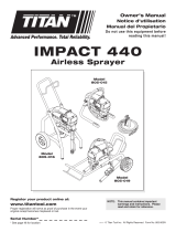
Owner’s Manual
Notice d’utilisation
Manual del Propietario
Do not use this equipment before
reading this manual!
Register your product online at:
www.titantool.com
Serial Number* _ _ _ _ _ _ _ _ _ _
* See page 48 for location
IMPACT 410
Airless Sprayer
Model
0532053
Model
0532052

English English
2 © Titan Tool Inc. All rights reserved.
Important Safety Information
Read all safety information before operating the
equipment. Save these instructions.
Indicates a hazardous situation which, if not avoided,
could result in death or serious injury.
To reduce the risks of re or explosion, electrical shock
and the injury to persons, read and understand all
instructions included in this manual. Be familiar with the
controls and proper usage of the equipment.
Grounding Instructions
This product must be grounded. In the event of an electrical short circuit,
grounding reduces the risk of electric shock by providing an escape wire
for the electric current. This product is equipped with a cord having a
grounding wire with an appropriate grounding plug. The plug must
be plugged into an outlet that is properly installed and grounded in
accordance with all local codes and ordinances.
WARNING - Improper installation of the grounding plug
can result in a risk of electric shock.
If repair or replacement of the cord or plug is necessary, do not connect
the green grounding wire to either at blade terminal. The wire with
insulation having a green outer surface with or without yellow stripes is
the grounding wire and must be connected to the grounding pin.
Check with a qualied electrician or serviceman if the grounding
instructions are not completely understood, or if you are in doubt as
to whether the product is properly grounded. Do not modify the plug
provided. If the plug will not t the outlet, have the proper outlet
installed by a qualied electrician.
This product is for use on a nominal 120 volt circuit and has a grounding
plug that looks like the plug illustrated below. Make sure that the product
is connected to an outlet having the same conguration as the plug. No
adapter should be used with this product.
Grounded Outlet
Grounding Pin
Cover for grounded outlet box
IMPORTANT: When the sprayer is used with a generator
or uncontrolled line voltage, the use of Titan’s “Line Surge
Protector” (P/N 800-935) is recommended.
WARNING: EXPLOSION OR FIRE
Solvent and paint fumes can explode or ignite. Property
damage and/or severe injury can occur.
PREVENTION:
• Do not spray ammable or combustible materials near an open
ame, pilot lights or sources of ignition such as hot objects,
cigarettes, motors, electrical equipment and electrical appliances.
Avoid creating sparks from connecting and disconnecting power
cords.
• Use extreme caution when using materials with a ashpoint
below 100ºF (38ºC). Flashpoint is the temperature that a uid can
produce enough vapors to ignite.
• Paint or solvent owing through the equipment is able to result
in static electricity. Static electricity creates a risk of re or
explosion in the presence of paint or solvent fumes. All parts
of the spray system, including the pump, hose assembly, spray
gun and objects in and around the spray area shall be properly
grounded to protect against static discharge and sparks. Use only
conductive or grounded high-pressure airless paint sprayer hoses
specied by the manufacturer.
• Verify that all containers and collection systems are grounded to
prevent static discharge.
• Connect to a grounded outlet and use grounded extension cords
(electric models only). Do not use a 3 to 2 adapter.
• Do not use a paint or solvent containing halogenated
hydrocarbons. Such as chlorine, bleach mildewcide, methylene
chloride and trichloroethane. They are not compatible with
aluminum. Contact the coating supplier about compatibility of
material with aluminum.
• Keep spray area well ventilated. Keep a good supply of fresh air
moving through the area to keep the air within the spray area free
from accumulation of ammable vapors. Keep pump assembly in
well ventilated area. Do not spray pump assembly.
• Do not smoke in the spray area.
• Do not operate light switches, engines, or similar spark producing
products in the spray area.
• Keep area clean and free of paint or solvent containers, rags, and
other ammable materials.
• Know the contents of the paint and solvents being sprayed.
Read all Material Safety Data Sheets (SDS) and container labels
provided with the paints and solvents. Follow the paint and
solvent manufacture’s safety instructions.
• Place pump at least 25 feet (7.62 meters) from the spray object in
a well ventilated area (add more hose if necessary). Flammable
vapors are often heavier than air. Floor area must be extremely
well ventilated. The pump contains arcing parts that emit sparks
and can ignite vapors.
• Plastic can cause static sparks. Never hang plastic to enclose spray
area. Do not use plastic drop cloths when spraying ammable
material.
• Fire extinguisher equipment shall be present and working.
WARNING: INJECTION INJURY
A high pressure paint stream produced by this equipment
can pierce the skin and underlying tissues, leading to
serious injury and possible amputation. See a physician
immediately.
PREVENTION:
• Do not aim the gun at, or spray any person or animal.
• Keep hands and other body parts away from the discharge. For
example, do not try to stop leaks with any part of the body.
• NEVER put your hand in front of the gun. Gloves will not provide
protection against an injection injury.
• ALWAYS keep the tip guard in place while spraying. The tip guard
provides some protection but is mainly a warning device.
• Only use a nozzle tip specied by the manufacturer.
• Use caution when cleaning and changing nozzle tips. In the
case where the nozzle tip clogs while spraying, ALWAYS lock
gun trigger, shut pump o, and release all pressure before
servicing, cleaning tip or guard, or changing tip. Pressure will
not be released by turning o the motor. The PRIME/SPRAY
valve or pressure bleed valve must be turned to their appropriate
positions to relieve system pressure. Refer to PRESSURE RELIEF
PROCEDURE described in the pump manual.
• Do not leave the unit energized or under pressure while
unattended. When the unit is not in use, turn o the unit and
relieve the pressure in accordance with the manufacturer’s
instructions.
• High-pressure spray is able to inject toxins into the body and
cause serious bodily injury. In the event that injection occurs,
seek medical attention immediately.
• Check hoses and parts for signs of damage, a leak can inject
material into the skin. Inspect hose before each use. Replace any
damaged hoses or parts.
Only use TITAN original-high-pressure
hoses in order to ensure functionality, safety and durability.

English English
© Titan Tool Inc. All rights reserved. 3
Important Safety Information
• This system is capable of producing 3000 PSI / 207 Bar. Only
use replacement parts or accessories that are specied by the
manufacturer and that are rated a minimum of 3000 PSI. This
includes spray tips, nozzle guards, guns, extensions, ttings, and
hose.
• Always engage the trigger lock when not spraying. Verify the
trigger lock is functioning properly.
• Verify that all connections are secure before operating the unit.
• Know how to stop the unit and bleed pressure quickly. Be
thoroughly familiar with the controls. Pressure will not be
released by turning o the motor. The PRIME/SPRAY valve
or pressure bleed valve must be turned to their appropriate
positions to relieve system pressure. Refer to PRESSURE RELIEF
PROCEDURE described in the pump manual.
• Always remove the spray tip before ushing or cleaning the
system.
NOTE TO PHYSICIAN:
Injection into the skin is a traumatic injury which can lead to
possible amputation. It is important to treat the injury as soon as
possible. DO NOT delay treatment to research toxicity. Toxicity
is a concern with some coatings injected directly into the blood
stream. Consultation with a plastic surgeon or reconstructive hand
surgeon may be advisable.
WARNING: HAZARDOUS VAPORS
Paints, solvents, insecticides, and other materials can
be harmful if inhaled or come in contact with the body.
Vapors can cause severe nausea, fainting, or poisoning.
PREVENTION:
• Use a respirator or mask if vapors can be inhaled. Read all
instructions supplied with the mask to be sure it will provide the
necessary protection.
• Wear protective eyewear.
• Wear protective clothing as required by coating manufacturer.
WARNING: GENERAL
Can cause severe injury or property damage.
PREVENTION:
• Always wear appropriate gloves, eye protection, clothing and a
respirator or mask when painting.
• Do not operate or spray near children. Keep children away from
equipment at all times.
• Do not overreach or stand on an unstable support. Keep eective
footing and balance at all times.
• Stay alert and watch what you are doing.
• Do not operate the unit when fatigued or under the inuence of
drugs or alcohol.
• Do not kink or over-bend the hose. Airless hose can develop leaks
from wear, kinking and abuse. A leak can inject material into the
skin.
• Do not expose the hose to temperatures or pressures in excess of
those specied by manufacturer.
• Do not use the hose as a strength member to pull or lift the
equipment.
• Use lowest possible pressure to ush equipment.
• Follow all appropriate local, state and national codes governing
ventilation, re prevention and operation.
• The United States Government Safety Standards have been
adopted under the Occupational Safety and Health Act (OSHA).
These standards, particularly part 1910 of the General Standards
and part 1926 of the Construction Standards should be consulted.
• Before each use, check all hoses for cuts, leaks, abrasion or
bulging of cover. Check for damage or movement of couplings.
Immediately replace hose if any of those conditions exist. Never
repair a paint hose. Replace with a conductive high-pressure
hose.
• Do not spray outdoors on windy days.
• Always unplug cord from outlet before working on equipment
(electric models only).
Specications
Gallons per minute (GPM) 0.47 (1.8 LPM)
Maximum tip sizes 0.021”
Maximum pressure 3000 PSI (20.7 MPa)
Power 0.75 HP PMDC brushed motor, 120VAC
Maximum hose length 300’ (91.4 m)
Generator requirement 5000 Watt (disable idle-down feature)
Table of Contents
Safety Precautions ........................................................................... 2
Specications ................................................................................... 3
General Description ........................................................................ 4
Operation ......................................................................................... 4
Setup ................................................................................................................. 4
Preparing to Paint.........................................................................................5
Painting ............................................................................................................ 5
Pressure Relief Procedure ..........................................................................6
Spraying ........................................................................................... 6
Spraying Technique .....................................................................................6
Practice ............................................................................................................. 6
Cleanup ............................................................................................ 7
Cleaning the Spray Tip ................................................................................7
Maintenance .................................................................................... 8
General Repair and Service Notes ..........................................................8
Replacing the Motor ....................................................................................9
Replacing the Motor Brushes ................................................................... 9
Replacing the Gears .....................................................................................9
Replacing the Transducer ........................................................................10
Replacing the PRIME/SPRAY Valve .......................................................10
Servicing the Fluid Section ......................................................................11
Replacing the Filters ..................................................................................12
Troubleshooting ............................................................................ 12
Parts Listings .................................................................................. 38
Main Assembly ............................................................................................38
Suction System for Stand .........................................................................38
Fluid Section Assembly ............................................................................40
Drive Assembly ............................................................................................42
Motor Assembly ..........................................................................................44
Cart Assembly ..............................................................................................45
Stand Assembly ...........................................................................................46
Labels ..............................................................................................................47
Electrical Schematic ...................................................................................47
Product Registration ..................................................................... 48
Accessories ....................................................................................................49
Warranty ........................................................................................ 50

English English
4 © Titan Tool Inc. All rights reserved.
General Description
This airless sprayer is a precision power tool used for spraying
many types of materials. Read and follow this instruction manual
carefully for proper operating instructions, maintenance, and safety
information.
Pressure Control
Knob
ON/OFF
Switch
PRIME/SPRAY
Valve
Outlet Fitting
Circuit
Breaker
Oil Cup
Siphon
Tube
Return
Hose
Filter
Operation
This equipment produces a fluid stream at extremely
high pressure. Read and understand the warnings
in the Safety Precautions section at the front of this
manual before operating this equipment.
Using the Gun Trigger Lock
Always engage the gun’s trigger lock when the gun is not in use.
1. To lock the trigger, push in the trigger lock from left to right,
when looking at the rear of the gun.
2. To unlock the trigger, push the trigger lock from right to left,
when looking at the rear of the gun.
12
Gun locked
(gun will not spray)
Gun unlocked
(gun will spray)
Setup
Perform the following procedure before plugging in the power cord
of an electric unit.
1. Ensure that the siphon tube and the return hose are attached
and secure.
2. Using a wrench, attach a minimum of 50’ of 1/4” airless spray
hose to the outlet tting on the sprayer. Tighten securely.
3. Attach an airless spray gun to the spray hose. Using two
wrenches (one on the gun and one on the hose), tighten
securely.
NOTE: Do not attach the tip to the spray gun yet. Remove
the tip if it is already attached.
Make sure all airless hoses and spray guns are
electrically grounded and rated at or above the
maximum operating pressure range of the airless
sprayer.
4. Make sure the pressure control knob is turned fully
counterclockwise to its lowest pressure setting.
5. Make sure the ON/OFF switch is in its OFF position.
6. Fill the oil cup with approximately one tablespoon of
separating oil (P/N 314-481).
IMPORTANT: Never operate unit for more than ten seconds
without fluid. Operating this unit without fluid will cause
unnecessary wear to the packings.
7. Make sure the electrical service is 120V, 15 amp minimum.
8. Plug the power cord into a properly grounded outlet at least
25’ from the spray area.
IMPORTANT: Always use a minimum 12 gauge, three-wire
extension cord with a grounded plug. Never remove the third
prong or use an adapter.
Preparing a New Sprayer
If this sprayer is new, it is shipped with test uid in the uid section to
prevent corrosion during shipment and storage. This uid must be
thoroughly cleaned out of the system with mineral spirits before you
begin spraying.
IMPORTANT: Always keep the trigger lock on the spray gun in
the locked position while preparing the system.
1. Place the siphon tube into a container of mineral spirits.
2. Place the return hose into a metal waste container.
3. Set the pressure to minimum by turning the pressure control
knob fully counterclockwise.
Pressure Contro
l
Knob
ON/OFF
Switch
4. Move the PRIME/SPRAY valve down to the
PRIME position.
5. Turn on the sprayer by moving the ON/OFF
switch to the ON position.
6. Allow the sprayer to run for 15–30 seconds
to ush the test uid out through the
return hose and into the waste container.
7. Turn o the sprayer by moving the ON/OFF switch to the OFF
position.

English English
© Titan Tool Inc. All rights reserved. 5
Preparing to Paint
Before painting, it is important to make sure that the uid in the
system is compatible with the paint that is going to be used.
NOTE: Incompatible uids and paint may cause the valves
to become stuck closed, which would require
disassembly and cleaning of the sprayer’s uid
section.
IMPORTANT: Always keep the trigger lock on the spray gun in
the locked position while preparing the system.
1. Place the siphon tube into a container of the appropriate
solvent. Examples of the appropriate solvent are water for
latex paint or mineral spirits for oil-based paints.
2. Place the return hose into a metal waste container.
3. Set the pressure to minimum by turning the pressure control
knob fully counterclockwise.
4. Move the PRIME/SPRAY valve down to the PRIME position.
NOTE: Hold the return hose in the waste
container when moving the PRIME/
SPRAY valve to PRIME in case the
sprayer is pressurized.
5. Turn on the sprayer by moving the ON/OFF switch to the ON
position.
6. Allow the sprayer to run for 15–30 seconds to ush the old
solvent out through the return hose and into the metal waste
container.
7. Turn o the sprayer by moving the ON/OFF switch to the OFF
position.
NOTE: Make sure that the spray gun does not have a tip or
tip guard installed.
8. Move the PRIME/SPRAY valve up to
the SPRAY position.
9. Turn on the sprayer.
10. Unlock the gun by pushing the gun
trigger lock to the unlocked position.
Ground the gun by holding it against
the edge of the metal container
while flushing. Failure to do so may
lead to a static electric discharge,
which may cause a fire.
11. Trigger the gun into the metal waste container until the old
solvent is gone and fresh solvent is coming out of the gun.
12. Lock the gun by pushing the gun trigger lock to the locked
position.
13. Set down the gun and increase the pressure by turning the
pressure control knob slowly clockwise.
14. Check the entire system for leaks. If leaks occur, follow the
“Pressure Relief Procedure” in this manual before tightening
any ttings or hoses.
15. Follow the “Pressure Relief Procedure” in this manual before
changing from solvent to paint.
Be sure to follow the pressure relief procedure when
shutting down the sprayer for any purpose, including
servicing or adjusting any part of the spray system,
changing or cleaning spray tips, or preparing for
cleanup.
Painting
1. Place the siphon tube into a container of paint.
2. Place the return hose into a metal waste container.
3. Set the pressure to minimum by turning the pressure control
knob fully counterclockwise.
Pressure Contro
l
Knob
ON/OFF
Switch
4. Move the PRIME/SPRAY valve down to the
PRIME position.
5. Turn on the sprayer by moving the ON/OFF
switch to the ON position.
6. Allow the sprayer to run until paint is
coming through the return hose into the
metal waste container.
7. Turn o the sprayer by moving the ON/OFF switch to the OFF
position.
8. Remove the return hose from the waste container and place it
in its operating position above the container of paint.
9. Move the PRIME/SPRAY valve up to
the SPRAY position.
10. Turn on the sprayer.
11. Unlock the gun by turning the gun
trigger lock to the unlocked position.
Ground the gun by holding it against
the edge of the metal container
while flushing. Failure to do so may
lead to a static electric discharge,
which may cause a fire.
12. Trigger the gun into the metal waste container until all air and
solvent is ushed from the spray hose and paint is owing
freely from the gun.
12. Lock the gun by pushing the gun trigger lock to the locked
position.
14. Turn o the sprayer.
15. Attach tip guard and tip to the gun as instructed by the tip
guard or tip manuals.
POSSIBLE INJECTION HAZARD. Do not spray without
the tip guard in place. Never trigger the gun unless
the tip is in either the spray or the unclog position.
Always engage the gun trigger lock before removing,
replacing or cleaning tip.
16. Turn on the sprayer.
17. Increase the pressure by turning the pressure control knob
slowly clockwise and test the spray pattern on a piece of
cardboard. Adjust the pressure control knob until the
spray from the gun is completely atomized. Try to keep the
pressure control knob at the lowest setting that maintains
good atomization.
NOTE: Turning the pressure up higher than needed to
atomize the paint will cause premature tip wear and
additional overspray.

English English
6 © Titan Tool Inc. All rights reserved.
Pressure Relief Procedure
Be sure to follow the Pressure Relief Procedure when
shutting down the sprayer for any purpose, including
servicing or adjusting any part of the spray system,
changing or cleaning spray tips, or preparing for
cleanup.
1. Lock the gun by pushing the gun trigger lock to the locked
position.
2. Turn o the sprayer by moving the ON/OFF switch to the OFF
position.
3. Set the pressure to minimum by turning the pressure control
knob fully counterclockwise.
4. Unlock the gun by pushing the gun trigger lock to the
unlocked position.
5. Hold the metal part of the gun
rmly to the side of a metal
container to ground the gun and
avoid a build up of static electricity.
6. Trigger the gun to remove any
pressure that may still be in the
hose.
7. Lock the gun by pushing the gun
trigger lock to the locked position.
8. Move the PRIME/SPRAY valve
down to the PRIME position.
Spraying
POSSIBLE INJECTION HAZARD. Do not spray without
the tip guard in place. Never trigger the gun unless
the tip is in either the spray or the unclog position.
Always engage the gun trigger lock before removing,
replacing, or cleaning tip.
Spraying Technique
The following techniques, if followed, will assure professional
painting results.
Hold the gun perpendicular to the surface and always at equal
distance from the surface. Depending on the type of material,
surface, or desired spray pattern, the gun should be held at a distance
of 12 to 14 inches (30 to 35 cm).
Move the gun either across or up and down the surface at a steady
rate. Moving the gun at a consistent speed conserves material and
provides even coverage. The correct spraying speed allows a full, wet
coat of paint to be applied without runs or sags.
Holding the gun closer to the surface deposits more paint on the
surface and produces a narrower spray pattern. Holding the gun
farther from the surface produces a thinner coat and wider spray
pattern. If runs, sags, or excessive paint occur, change to a spray tip
with a smaller orice. If there is an insucient amount of paint on
the surface or you desire to spray faster, a larger orice tip should be
selected.
Maintain uniform spray stroke action. Spray alternately from left to
right and right to left. Begin movement of the gun before the trigger
is pulled.
start
stroke
release
trigger
pull
trigger
end
stroke
Avoid arcing or holding the gun at an angle. This will result in an
uneven nish.
Too Thick
Ospray
Arcing Gun at angle

English English
© Titan Tool Inc. All rights reserved. 7
Proper lapping (overlap of spray pattern) is essential to an even nish.
Lap each stroke. If you are spraying horizontally, aim at the bottom
edge of the preceding stroke, so as to lap the previous pattern by
50%.
Overlap edges
1st
pass
2nd
pass
3rd
pass
4th
pass
5th
pass
For corners and edges, split the
center of the spray pattern on the
corner or edge and spray vertically
so that both adjoining sections
receive approximately even
amounts of paint.
When spraying with a shield, hold it rmly against the surface. Angle
the spray gun slightly away from the shield and toward the surface.
This will prevent paint from being forced underneath.
Shrubs next to houses should be tied back and covered with a canvas
cloth. The cloth should be removed as soon as possible. Titan gun
extensions are extremely helpful in these situations.
Nearby objects such as automobiles, outdoor furniture, etc. should
be moved or covered whenever in the vicinity of a spray job. Be
careful of any other surrounding objects that could be damaged by
overspray.
Practice
1. Be sure that the paint hose is free of kinks and clear of objects
with sharp cutting edges.
2. Set the pressure to minimum by turning the pressure control
knob fully counterclockwise.
3. Move the PRIME/SPRAY valve up to its SPRAY position.
4. Turn the pressure control knob clockwise to its highest
setting. The paint hose should stien as paint begins to ow
through it.
5. Unlock the gun trigger lock.
6. Trigger the spray gun to bleed air out of the hose.
7. When paint reaches the spray tip, spray a test area to check
the spray pattern.
Good spray pattern
Paint tailing pattern
8. Use the lowest pressure setting
necessary to get a good spray
pattern. If the pressure is set
too high, the spray pattern will
be too light. If the pressure is
set too low, tailing will appear
or the paint will spatter out in
gobs rather than in a ne spray.

English English
8 © Titan Tool Inc. All rights reserved.
Cleanup
Special cleanup instructions for use with flammable
solvents:
• Always ush spray gun preferably outside and at least one
hose length from spray pump.
• If collecting ushed solvents in a one gallon metal container, place
it into an empty ve gallon container, then ush solvents.
• Area must be free of ammable vapors.
• Follow all cleanup instructions.
IMPORTANT: The sprayer, hose, and gun should be cleaned
thoroughly after daily use. Failure to do so permits material to
build up, seriously affecting the performance of the unit.
Always spray at minimum pressure with the gun
nozzle tip removed when using mineral spirits or any
other solvent to clean the sprayer, hose, or gun. Static
electricity buildup may result in a fire or explosion in
the presence of flammable vapors.
1. Follow the “Pressure Relief Procedure” found in the Operation
section of this manual.
2. Remove the gun tip and tip guard and clean with a brush
using the appropriate solvent.
3. Place the siphon tube into a container of the appropriate
solvent. Examples of the appropriate solvent are water for
latex paint or mineral spirits for oil-based paints.
4. Place the return hose into a metal waste container.
5. Set the pressure to minimum by turning the pressure control
knob fully counterclockwise.
6. Move the PRIME/SPRAY valve down to its PRIME position.
NOTE: Hold the return hose in the waste container when
moving the PRIME/SPRAY valve to PRIME in case the
sprayer is pressurized.
7. Turn on the sprayer by moving the ON/OFF switch to the ON
position.
8. Allow the solvent to circulate through the unit and ush the
paint out of the return hose into the metal waste container.
9. Turn o the sprayer by moving the ON/OFF switch to the OFF
position.
10. Move the PRIME/SPRAY valve up to its SPRAY position.
11. Turn on the sprayer.
Ground the gun by holding it against the edge of the
metal container while flushing. Failure to do so may
lead to a static electric discharge, which may cause a
fire.
12. Trigger the gun into the metal waste container until the paint
is ushed out of the hose and solvent is coming out of the
gun.
13. Continue to trigger the spray gun into the waste container
until the solvent coming out of the gun is clean.
NOTE: For long-term or cold weather storage, pump
mineral sprits through the entire system.
For short-term storage when using latex paint,
pump water mixed with Titan Liquid Shield through
the entire system (see the Accessories section of this
manual for part number).
14. Follow the “Pressure Relief Procedure” found in the Operation
section of this manual.
15. Unplug the unit and store in a clean, dry area.
IMPORTANT: Do not store the unit under pressure.
Maintenance
Before proceeding, follow the “Pressure Relief
Procedure” outlined previously in this manual.
Additionally, follow all other warnings to reduce the
risk of an injection injury, injury from moving parts
or electric shock. Always unplug the sprayer before
servicing!
General Repair and Service Notes
The following tools are needed when repairing this sprayer:
Phillips Screwdriver 3/8” Hex Wrench
Needle Nose Pliers 5/16” Hex Wrench
Adjustable Wrench 1/4” Hex Wrench
Rubber Mallet 3/16” Hex Wrench
Flat-blade Screwdriver 1/8” hex wrench
1/2” open-end wrench 7/8” open-end wrench
1. Before repairing any part of the sprayer, read the instructions
carefully, including all warnings.
IMPORTANT: Never pull on a wire to disconnect it. Pulling on a
wire could loosen the connector from the wire.
2. Test your repair before regular operation of the sprayer to be
sure that the problem is corrected. If the sprayer does not
operate properly, review the repair procedure to determine if
everything was done correctly. Refer to the Troubleshooting
Charts to help identify other possible problems.
3. Make certain that the service area is well ventilated in case
solvents are used during cleaning. Always wear protective
eyewear while servicing. Additional protective equipment
may be required depending on the type of cleaning solvent.
Always contact the supplier of solvents for recommendations.
4. If you have any further questions concerning your Titan Airless
Sprayer, call Titan:
Customer Service (U.S.) ..................................... 1-800-526-5362
Fax ................................................................. 1-800-528-4826

English English
© Titan Tool Inc. All rights reserved. 9
Replacing the Motor
1. Perform the Pressure Relief Procedure and unplug the sprayer.
2. Remove the four motor cover screws. Remove the motor
cover.
3. Remove the four heat sink assembly screws. Pull the heat sink
assembly away from the gear box housing.
4. Disconnect the ve wires from the relay that is mounted on
the inside of the heat sink assembly.
5. Connect the ve wires to the new relay (refer to the electrical
schematic in the Parts List section of this manual).
6. Using the four heat sink assembly screws, install the heat sink
assembly onto the gear box housing. Tighten the screws
securely.
7. Disconnect the black and red wires coming from the gear
box housing. Disconnect the black and red wires from the
capacitors. Disconnect the black and red wires from the
motor.
8. Loosen and remove the four motor mounting screws.
9. Pull the motor out of the gear box housing.
NOTE: If the motor will not dislodge from the pump
housing:
• Remove the front cover plate.
• Using a rubber mallet, carefully tap on the front of
the motor crankshaft that extends through the slider
assembly.
10. With the motor removed, inspect the gears in the gear box
housing for damage or excessive wear. Replace the gears, if
necessary.
11. Install the new motor into the gear box housing.
NOTE: Rotate the motor fan manually until the armature
gear engages with the mating gear in the gear box
housing.
12. Secure the motor with the four motor mounting screws.
13. Push the new capacitors into their clip on the new motor.
14. Reconnect the wires (refer to the electrical schematic in the
Parts List section of this manual).
15. Slide the motor cover over the motor. Secure the motor cover
with the four motor cover screws.
Motor
cover
screw
Heat sink
assembly screw
Heat sink
assembly
Fan
shroud
screw
Fan
shroud
Brush
cover
Motor
Motor
mounting
screw
Gear box
housing
Capacitors
Motor cover
BLACK
BLACK
RED
BLACK
RED
RED
Replacing the Motor Brushes
Perform this procedure using Motor Brush Kit P/N 0508645.
1. Perform the Pressure Relief Procedure and unplug the sprayer.
2. Loosen and remove the four motor cover screws. Remove the
motor cover.
3. Loosen and remove the two fan shroud screws. Remove the
fan shroud.
4. Using a small screwdriver, pry o the two plastic brush covers.
5. Disconnect the black and red wires from the motor brushes.
Remove the motor brushes.
6. Install the new motor brushes and snap on the plastic brush
covers.
7. Reconnect the black and red wires from the motor brushes
(refer to the electrical schematic in the Parts List section of this
manual).
8. Position the fan shroud over the motor fan. Secure the fan
shroud with the two fan shroud screws.
9. Slide the motor cover over the motor. Secure the motor cover
with the four motor cover screws.
Replacing the Gears
1. Perform the Pressure Relief Procedure and unplug the sprayer.
2. Loosen and remove the four motor cover screws. Remove the
motor cover.
3. Disconnect the black and red wires coming from the gear box
housing.
4. Loosen and remove the four motor mounting screws.
5. Pull the motor out of the gear box housing.
NOTE: If the motor will not dislodge from the pump
housing:
• Remove the front cover plate.
• Using a rubber mallet, carefully tap on the front
of the motor crankshaft that extends through the
slider assembly.
6. Inspect the armature gear on the end of the motor for
damage or excessive wear. If this gear is completely worn out,
replace the entire motor.
7. Remove and inspect the 2nd stage gear for damage or
excessive wear. Replace if necessary.
8. Remove and inspect the crankshaft/gear assembly for damage
or excessive wear. Replace if necessary.
9. Reassemble the pump by reversing the above steps. During
reassembly, make sure the thrust washers is in place.
NOTE: Rell the gear box in the pump housing with ve
ounces of grease (P/N 0293396).
Front cover
Gear box housing
Front cover screw
2nd stage gear
Thrust washer
Mot
or mounting
screw
Crankshaft/gear
assembly
Armature gear
Motor
Motor cover
Motor cover screw

English English
10 © Titan Tool Inc. All rights reserved.
Replacing the Transducer
1. Loosen and remove the four front cover screws. Remove the
front cover.
2. Stop the sprayer at the bottom of its stroke so that the piston
is in its lowest position.
3. Perform the Pressure Relief Procedure and unplug the sprayer.
Before proceeding, follow the Pressure Relief
Procedure outlined previously in this manual.
Additionally, follow all other warnings to reduce the
risk of an injection injury, injury from moving parts
or electric shock. Always unplug the sprayer before
servicing!
4. Tilt the sprayer back for easy access to the uid section.
5. Using a 3/8” hex wrench, loosen and remove the two socket
screws.
6. Pull the uid section down approximately 1/2” from the
housing to clear the transducer.
7. Slide the uid section and piston rod forward until the piston
rod is out of the T-slot on the connecting rod.
8. Using a wrench, remove the transducer assembly from the
uid section.
9. Thread the new transducer assembly from the uid section.
Tighten securely with a wrench.
10. Reassemble the pump by reversing steps 1-8.
IMPORTANT: Make sure the transducer is aligned properly
with the hole in the fluid section during reassembly. Improper
alignment may cause damage to the transducer O-ring.
T-slot
Gear box
housing
Slider
assembly
Pump
manifold
mounting
screw
Front
cover
screw
Front
cove
r
Transducer
assembly
Pump
manifold
Replacing the PRIME/SPRAY Valve
Perform the following procedure using PRIME/SPRAY valve
replacement kit P/N 0507690.
1. Drive the groove pin out of the valve handle.
2. Remove the valve handle and the cam base.
3. Using a wrench, loosen and remove the valve housing
assembly from the pump manifold.
4. Make sure the gasket is in place and thread the new valve
housing assembly into the pump manifold. Tighten securely
with a wrench.
5. Place the cam base over the valve housing assembly.
Lubricate the cam base with grease and line up the cam with
the pump manifold using the dowel pin.
6. Line up the hole on the valve stem with the hole in the valve
handle.
7. Insert the groove pin into the valve handle and through the
valve stem to secure the valve handle in position.
Dowel pin
Groove pin
Valve stem
Gasket
Pump
manif
old
Valve housing
assembly
Valve
handle
Cam base

English English
© Titan Tool Inc. All rights reserved. 11
Servicing the Fluid Section
Use the following procedures to service the valves and repack the
uid section. Perform the following steps before performing any
maintenance on the uid section.
1. Loosen and remove the four front cover screws. Remove the
front cover.
2. Stop the sprayer at the bottom of its stroke so that the piston
is in its lowest position.
3. Perform the Pressure Relief Procedure and unplug the sprayer.
Before proceeding, follow the Pressure Relief
Procedure outlined previously in this manual.
Additionally, follow all other warnings to reduce the
risk of an injection injury, injury from moving parts
or electric shock. Always unplug the sprayer before
servicing!
4. Unscrew the return hose assembly from the pump block.
Remove the retaining clip from the bottom of the foot valve
housing. Remove the siphon assembly.
5. Tilt the sprayer back for easy access to the uid section.
Inlet valve
housing
Teon
O-ring
Inlet valve
seat
Inlet valve
ball
Inlet valve
cage
Nylon
washer
Piston
bushing
Pump
manifold
Servicing the Valves
The design of the uid section allows
access to the foot valve and seat
as well as the outlet valve and seat
without completely disassembling
the uid section. It is possible that
the valves may not seat properly
because of debris stuck in the foot
valve seat or outlet valve seat. Use
the following instructions to clean
the valves and reverse or replace the
seats.
1. Using a wrench, loosen and
remove the inlet valve housing
from the pump block.
2. Clean out any debris in the
inlet valve housing and
examine the valve housing
and seat. If the seat is
damaged, reverse or replace
the seat.
3. Using a 5/16” hex wrench, loosen and remove the outlet valve
retainer from the piston rod.
Outlet valve
retainer
Outlet valve
seat
Outlet valve
ball
Crush
washer
Outlet valve
cage
Piston rod
NOTE: Always service the outlet
valve with the piston rod
attached to the pump.
This will prevent the
piston rod from rotating
during disassembly of
the outlet valve.
5. Clean out any debris and examine
the outlet valve housing and seat.
If the seat is damaged, reverse or
replace the seat.
6. Remove, clean, and inspect the
outlet cage, crush washer, and outlet valve ball. Replace if
they are worn or damaged.
NOTE: The outlet cage always must be used with the
crush washer. They are included together in the
repacking kit as assembly P/N 704-642.
7. Reassemble the valves by reversing the steps above.
NOTE: During reassembly of the outlet valve, apply one
drop of Loctite (included in the repacking kit) to
the threads of the outlet valve retainer before
threading it into the piston rod. Then, torque the
retainer to 144 in./lbs. (12 ft./lbs.).
Repacking the Fluid Section
1. Remove the foot valve assembly using the steps in the
“Servicing the Valves” procedure above.
NOTE: The outlet valve does not need to be disassembled
from the piston rod for this procedure.
Slider assembly
Retainer nut
Piston guide
Upper packing
assembly
Pump manifold
Pump manifold
mounting screw
Piston rod
Lower packing
assembly
T
-slot
2. Using 3/8” a hex
wrench, loosen and
remove the two pump
block mounting screws.
3. Pull the pump block
down approximately
1/2” from the pump
housing.
4. Slide the pump block
and piston rod forward
until the piston rod is
out of the T-slot on the
slider assembly.
5. Slide the piston rod out
through the bottom of
the pump block.
6. Loosen and remove the
retainer nut and piston
guide from the pump
block.
7. Remove the upper and
lower packings from
the pump block.
8. Clean the pump block
and install the new
upper and lower
packings. Refer to
the illustration below
for proper packing
orientation.
Install upper packing
with raised lip and O-ring
facing down.
O-Ring
Raised Lip
Beveled Edge
Install lower packing
with the beveled
edge facing up.
9. Inspect the piston rod for wear and replace if necessary.
10. Reassemble the outlet valve assembly into the piston rod.
Tighten the outlet valve retainer with a wrench until secure.
NOTE: Use the T-slot on the slider assembly to hold the
piston rod in position while securing the outlet
valve retainer.
IMPORTANT: Never use a wrench on the piston itself. This could
cause damage to the piston and cause leakage.
11. Insert the piston guide into the retainer nut. Thread the
retainer nut into the pump block until it is hand tight.
12. Slide the piston guide tool (included in the repacking kit) over
the top of the piston rod and insert the piston rod through
the bottom of the pump block. Using a rubber mallet, tap
the bottom of the piston rod lightly until the piston rod is in
position in the pump block.
NOTE: Coat the piston guide tool and the piston rod with
grease before inserting them into the pump block.
13. Using a wrench, tighten the retainer nut securely.

12 © Titan Tool Inc. All rights reserved.
English
14. Slide the top of the piston rod into the T-slot on the slider
assembly.
15. Position the pump block underneath the pump housing and
push up until it rests against the pump housing.
16. Thread the pump block mounting screws through the pump
block and into the pump housing. Tighten securely.
17. Reassemble the inlet valve assembly into the pump block.
18. For Upright Cart units - Thread the siphon tube into the inlet
valve and tighten securely. Make sure to wrap the threads on
the siphon tube with Teon tape before assembly. Replace
the return hose into the hose clip on the siphon tube.
19. For Stand / Low Boy units, insert the elbow on the suction set
assembly into the bottom of the inlet valve housing. Push
the retaining ring up into the groove inside the inlet valve
housing to secure the suction set assembly in position. Push
the return hose onto the return hose tting on the pump
manifold and secure in position with the return hose clamp.
20. Place the front cover on the pump housing and secure in
position using the four front cover screws.
21. Turn on the sprayer by following the procedure in the
“Operation” section of this manual and check for leaks.
Replacing the Filters
Pump Filter
1. Loosen and remove the lter housing.
2. Pull the lter from the pump manifold.
NOTE: If the lter breaks o in the pump manifold, use a
small wood screw to remove.
3. Inspect the lter seal. Based on inspection, clean or replace
the seal.
4. Push the new or cleaned lter into the pump manifold.
5. Slide the lter housing over the lter and thread it into the
pump manifold until secure.
Filter housing
Filter
Filter seal
Pump manifold
Gun Filter
1. Unclip the top of the trigger guard from the gun body.
2. Using the bottom of the trigger guard as a wrench, loosen and
remove the handle assembly from the gun head.
3. Pull the old lter out of the gun body. Clean or replace.
4. Slide the new lter, tapered end rst, into the gun head.
5. Thread the handle assembly into the gun head. Tighten with
the trigger wrench.
6. Snap the trigger guard back onto the gun body.
Handle
Filter
Gun
Body
NOTE: For more detail, part number information, and
complete assembly drawings, please see the RX-80
Airless Gun Owner’s Manual.

English
© Titan Tool Inc. All rights reserved. 13
Problem
A. The unit will not run.
B. The unit will not prime.
C. The unit will not build or
maintain pressure.
D. Fluid leakage at the upper end
of the uid section.
E. Excessive surge at the spray
gun.
F. Poor spray pattern.
G. The unit lacks power.
Cause
1. The unit is not plugged in.
2. Tripped breaker.
3. The pressure is set too low (pressure control
knob set at minimum setting does not supply
power to unit).
4. Faulty or loose wiring.
5. Excessive motor temperature.
6. ON/OFF switch is defective.
1. The PRIME/SPRAY valve is in the SPRAY
position.
2. Air leak in the siphon tube/suction set.
3. The pump lter and/or inlet screen is clogged.
4. The siphon tube/suction set is clogged.
1. The spray tip is worn.
2. The spray tip is too large.
3. The pressure control knob is not set properly.
4. The pump lter, gun lter, or inlet screen is
clogged.
5. Material ows from the return hose when the
PRIME/SPRAY valve is in the SPRAY position.
6. Air leak in the siphon tube/suction set.
7. There is external uid leak.
8. There is an internal uid section leak
(packings are worn and/or dirty, valve balls
are worn).
9. Worn valve seats
10. Motor powers but fails to rotate
1. The upper packing is worn.
2. The piston rod is worn.
1. Wrong type of airless spray hose.
2. The spray tip worn or too large.
3. Excessive pressure.
1. The spray tip is too large for the material
being used.
2. Incorrect pressure setting.
3. Insucient uid delivery.
4. The material being sprayed is too viscous.
1. The pressure adjustment is too low.
2. Improper voltage supply.
Solution
1. Plug the unit in.
2. Reset the breaker.
3. Turn the pressure control knob clockwise to supply
power to the unit and increase the pressure setting.
4. Inspect or take to a Titan authorized service center.
5. Allow motor to cool.
6. Replace the ON/OFF switch.
1. Rotate the PRIME/SPRAY valve clockwise to the PRIME
position.
2. Check the siphon tube/suction set connection and
tighten or re-tape the connection with PTFE tape.
3. Remove the pump lter element and clean. Remove the
inlet screen and clean.
4. Remove the siphon tube/suction set and clean.
1. Replace the spray tip following the instructions that
came with the spray gun.
2. Replace the spray tip with a tip that has a smaller orice
following the instructions that came with the spray gun.
3. Turn the pressure control knob clockwise to increase the
pressure setting.
4. Remove the pump lter element and clean. Remove the
gun lter and clean. Remove the inlet screen and clean.
5. Clean or replace the PRIME/SPRAY valve.
6. Check the siphon tube/suction set connection and
tighten or re-tape the connection with PTFE tape.
7. Check for external leaks at all connections. Tighten
connections, if necessary.
8. Clean the valves and service the uid section following
the “Servicing the Fluid Section” procedure in the
Maintenance section of this manual.
9. Reverse or replace the valve seats following the
“Servicing the Fluid Section” procedure in the
Maintenance section of this manual.
10. Take unit to a Titan authorized service center.
1. Repack the pump following the “Servicing the Fluid
Section” procedure in the Maintenance section of this
manual.
2. Replace the piston rod following the “Servicing the Fluid
Section” procedure in the Maintenance section of this
manual.
1. Replace hose with a minimum of 50’ of 1/4” grounded
textile braid airless paint spray hose.
2. Replace the spray tip following the instructions that
came with the spray gun.
3. Rotate the pressure control knob counterclockwise to
decrease spray pressure.
1. Replace the spray tip with a new or smaller spray tip
following the instructions that came with the spray gun.
2. Rotate the pressure control knob to adjust the pressure
for a proper spray pattern.
3. Clean all screens and lters.
4. Add solvent to the material according to the
manufacturer’s recommendations.
1. Rotate the pressure control knob clockwise to increase
the pressure setting.
2. Reconnect the input voltage for 120V AC.
Troubleshooting

38 © Titan Tool Inc. All rights reserved.
Parts List • Liste de pièces • Lista de piezas
Main Assembly • Vue d’ensemble • Ensamblaje principal
1
3
4
5
9
6
7
8
10
11
12
2
17
18
19
16
13
14
14
15
1
3
2
4
7
6
5

© Titan Tool Inc. All rights reserved. 39
Item
Article
Articulo
Part No.
Nº de piéce
Pieza No.
English
Description
Français
Description
Español
Descripción
Quantity
Quantite
Cantidad
1 0558302 Motor cover Carter du moteur Cubierta del motor 1
2 0551440 Screw Vis Tornillo 4
3 9800308 Screw Vis Tornillo 4
4 ------- Motor assembly Ensemble de moteur Ensamblaje del motor 1
5 0551526 Left leg assembly (stand) Ensemble de patte, gauche
(support)
Ensamblaje de pata, izquierda
(soporte)
1
6 0551553 Pail hook (cart only) Support de seau (chariot) Soporte del cubo (carrito) 1
7 763-552 Washer (cart only) Rondelle (chariot) Arandela (carrito) 2
8 710-033 Screw (cart only) Vis (chariot) Tornillo (carrito) 2
9 730-334 Return tube clip (cart only) Agrafe de tube de retour
(chariot)
Abrazadera de tubo de retorno
(carrito)
1
10 705-054 Siphon tube (cart only) Tube de siphon (chariot) Tubo de sifón (carrito) 1
11 0551556 Return tube (cart only) Tube de retour (chariot) Tubo de retorno (carrito) 1
12 710-046 Inlet lter (cart only) Filtre d’entrée (chariot) Filtro de entrada (carrito) 1
13 ------- Drive assembly Boîte d’engrenages Ensamblaje de la caja de
engranajes
1
14 0509550 Screw (stand, cart) Vis (support, chariot) Tornillo (soporte, carrito) 4
15 0551524 Right leg assembly (stand) Ensemble de patte, droite
(support)
Ensamblaje de pata, derecha
(soporte)
16 0532468A Fluid section assembly (cart) Ensemble de section des
liquides (chariot)
Ensamblaje de sección de
líquidos (carrito)
1
0532467A Fluid section assembly (stand) Ensemble de section des
liquides (support)
Ensamblaje de sección de
líquidos (soporte)
1
17 704-117 Screw Vis Tornillo 4
18 0558672A Suction set assembly (stand) Dispositif d’aspiration (support) Conjunto de succión (soporte) 1
19 0327226 Return tube clip (cart only) Agrafe de tube de retour
(chariot)
Abrazadera de tubo de retorno
(carrito)
1
Suction Set Assembly • Ensemble d’aspiration • Ensamblaje del juego de succión
Item
Article
Articulo
Part No.
Nº de piéce
Pieza No.
English
Description
Français
Description
Español
Descripción
Quantity
Quantite
Cantidad
1 0558672A Siphon tube assembly (includes
items 1-7)
Ensemble d’aspiration
(comprend les articles 1-7)
Ensamblaje del juego de
succión (incluye articulos 1-7)
1
2 9850638 Tie wrap Cord d’amarrage Amarra 2
3 0558659A Return tube Tube de retour Tubo de retorno 1
4 0279459 Clip Agrafe Sujetador 1
5 700-805 Inlet screen Crépine d’entrée Malla de entrada 1
6 9871105 O-ring Joint torique Junta tórica 2
7 9822526 Retaining clip Agrafe de retenue Sujetador de retención 1
704-109 O-ring (for hot solvents,
optional)
Joint torique pour solvants
chauds (facultatif)
Junta tórica (para solventes
calientes, opcional)

40 © Titan Tool Inc. All rights reserved.
1
6
14
15
16
7
8
9
10
11
12
13
17
18
19
20
21
22
23
24
25
26
27
2
3
4
5
29
28
30
31
32
33
Install upper packing
with raised lip and
O-ring facing down.
O-Ring
Raised Lip
La partie surélevée et le
joint torique du tampon
supérieur doivent être
vers le bas.
Joint torique
Partie surélevée
Instale la empaquetadura
superior con el reborde
levantado y la junta tórica
apuntando hacia abajo.
Junta tórica
Reborde levantado
Install lower packing
with the beveled
edge facing up.
Beveled Edge
La bord biseauté
doivent être vers
le haut.
Bord biseauté
Instale la empaquetadura
inferior con borde
biselado hacia arriba.
Borde biselado
Fluid Section Assembly • Section de liquides • Sección de líquido

© Titan Tool Inc. All rights reserved. 41
Item
Article
Articulo
Part No.
Nº de piéce
Pieza No.
English
Description
Français
Description
Español
Descripción
Quantity
Quantite
Cantidad
1 730-508 Retainer Rondelle de retenue Retén 1
2 700-587 Piston guide Guide-piston Guía de piston 1
3 0532914 Upper packing Tampon graisseur supérieur Empaquetadura superior 1
4 0551531 Pump block Bloc pompe Bloque de la bomba 1
5 227-006 Fitting Raccord Conector 1
6 0507690 Bypass valve assembly Ensemble by-pass Conjunto de válvula de derivación 1
7 700-721 O-ring Joint torique Junta tórica 1
700-897 O-ring, PTFE (optional) Joint torique, PTFE (facultatif) Junta tórica, PTFE (opcional) 1
8 222-012 O-ring, PTFE Joint torique, PTFE Junta tórica, PTFE 1
9 221-012 O-ring Joint torique Junta tórica 1
10 700-537 Gasket Joint d’étanchéité Empaquetadura 1
11 700-252 Cam base Base à came Base de leva 1
12 700-759 Groove pin Goupille Pasador de surco 1
13 0507662 Valve handle Manette de soupape Mango de la válvula 1
14 0532915 Lower packing Tampon graisseur inférieur Ampaquetadura inferior 1
15 704-551A Piston rod Tige de piston Vara del pistón 1
16 704-610 Upper cage Cage supérieur Jaula superior 1
17 704-612 Crush washer Rondelle d’encrasement Arandela de aplastar 1
18 50164 Outlet valve ball Clapet de soupape de sortie Bola de la válvula de salida 1
19 704-558 Outlet valve seat Siège de soupape de sortie Asiento de la válvula de salida 1
20 13481 Outlet valve retainer Rondelle de retenue de soupape de
sortie
Retén de la válvula de salida 1
21 0509590 Bushing Manchon Buje 1
22 700-821 Inlet valve seal Joint de soupape de entrée Junta de la válvula de entrada 1
23 704-703 Lower cage Cage inférieur Jaula superior 1
24 762-145 Inlet valve ball Clapet de soupape de entrée Bola de la válvula de entrada 1
25 762-137 Inlet valve seat Siège de soupape de entrée Asiento de la válvula de entrada 1
26 762-058 O-ring, PTFE Joint torique, PTFE Junta tórica, PTFE 1
27 730-511 Inlet valve housing (cart) Logement de soupape de entrée
(chariot)
Caja de válvula de entrada (carrito) 1
704-054 Inlet valve housing (stand) Logement de soupape de entrée
(support)
Caja de válvula de entrada (soporte) 1
28 0551532 Filter assembly (includes
items 29-31)
Ensemble de ltre (comprend les
articles 29-31)
Ensamblaje del ltro (incluye los
articulos 29-31)
1
29 0516775 Filter housing Logement de ltre Caja del ltro 1
30 581-059 Filter Filtre Filtro 1
31 560-038 Seal Joint torique Junta tórica 1
32 193-200 Return tube tting Raccord de tube de retour Conector de tubo de retorno 1
33 704-552A Piston assembly (includes
items 15-19)
Ensemble de piston (comprend les
articles 15-19)
Ensamblaje del pistón (incluye los
articulos 15-19)
704-586 Repacking kit (includes
items 2-3, 14, 16-18, 22,
24, and 26).
Trousse de tampon graisseurs
(comprend les articles 2-3, 7, 16-18,
22, 24 et 26).
Juego de empaquetaduras (incluye
artículos 2-3, 7, 16-18, 22, 24 y 26.)

42 © Titan Tool Inc. All rights reserved.
Drive Assembly • Boîte d’engrenages • Ensamblaje de la caja de engranajes
1
2
3
7
8
9
10
11
12
24
13
14
15
16
4
5
6
17
16
18
19
20
22
21
23

© Titan Tool Inc. All rights reserved. 43
NOTE: All electrical work should be performed by an
authorized service center.
NOTA : Tous les travaux d’électricité doivent être eectués
par le personnel d’un centre de service autorisé.
NOTA: Todo trabajo eléctrico debe realizarlo un centro de
servicio autorizado.
Item
Article
Articulo
Part No.
Nº de piéce
Pieza No.
English
Description
Français
Description
Español
Descripción
Quantity
Quantite
Cantidad
1 700-139 Screw Vis Tornillo 4
2 0551518 Face plate Couvercle Cubierta frontal 1
3 0508208 Slider assembly Bielle Vara conectora 1
4 0508572 Crankshaft / gear assembly Ensemble vilebrequin/
engrenages
Ensamblaje cigüeñal/engranaje 1
5 704-174 Thrust washer Rondelle de butée Arandela de empuje 1
6 704-176 2nd stage gear Second embragage Engranaje de 2da etapa 1
7 0509219 Screw Vis Tornillo 1
8 700-771 Pressure control knob Bouton de réglage de pression Perilla de regulador de presión 1
9 0551522 Knob housing Logement de bouton Caja de perilla 1
10 02712 Spring Ressort Resorte 1
11 9822522 Washer Rondelle Arandela 1
12 806-032 Plunger Plongeur Contacto de presión 1
13 800-741 Power cord assembly (stand) Ensemble de cordon
d’alimentation (support)
Ensamblaje de cable de
alimentación (soporte)
1
806-213 Power cord assembly (cart) Ensemble de cordon
d’alimentation (chariot)
Ensamblaje de cable de
alimentación (carrito)
1
14 9800340 Ground screw Vis a terre Tornillo a tierra 1
15 0551112 Transducer Capteur de pression Impulsor manométrico 1
16 704-211A Circuit breaker Disjoncteur à maximum Interruptor protector de
sobrecarga
1
17 9850936 ON/OFF switch Interrupteur Interruptor 1
18 03662 Microswitch insulator Isolateur de micro interrupteur Aislante de micro-interruptor 1
19 0522633 Microswitch Micro interrupteur Micro-interruptor 1
20 9800604 Screw Vis Tornillo 1
21 704-281 Plug Fiche Tapón 1
22 700-139 Screw Vis Tornillo 4
23 0522143A Motor controller assembly Couvercle du dissipateur
thermique
Tapa del disipador de calor 1
24 806-100A Housing assembly (includes
item 17)
Logement de la pompe
(comprend le article 17)
Caja de la bomba (incluye
artículo 17)
1

© Titan Tool Inc. All rights reserved. 45
Item
Article
Articulo
Part No.
Nº de piéce
Pieza No.
English
Description
Français
Description
Español
Descripción
Quantity
Quantite
Cantidad
1 0551665 Cart weldment (includes item 5) Châssis de base (comprend le
élément 5)
Carrito (incluye artículo 5) 1
2 9890104 Axle cap Chapeau de roue Tapa de rueda 2
3 0294534 Spacer Entretoise Separador 4
4 0278373 Wheel Roue Rueda 2
5 0294635 Plug Bouchon Tapa 2
Cart Assembly • Ensemble de chariot • Ensamblaje de carro
(P/N 0551110)
1
2
3
5
4
/