Cisco Catalyst Pluggable Interface Module Owner's manual

Type
Owner's manual

Cisco Catalyst Pluggable Interface Module offers flexibility and scalability for your network. It enables you to add new interfaces or replace existing ones without disrupting your network operations. With support for various interface types, including Ethernet, serial, and wireless, this module provides versatile connectivity options. It's ideal for expanding the capabilities of your network devices, such as routers and switches, to meet evolving business needs and accommodate new technologies.

Cisco Catalyst Pluggable Interface Module offers flexibility and scalability for your network. It enables you to add new interfaces or replace existing ones without disrupting your network operations. With support for various interface types, including Ethernet, serial, and wireless, this module provides versatile connectivity options. It's ideal for expanding the capabilities of your network devices, such as routers and switches, to meet evolving business needs and accommodate new technologies.

Cisco Catalyst Pluggable Interface Module
This section provides information before and during the installation of Cisco Catalyst Pluggable Interface
Module (PIM) on the Cisco Catalyst 8200 Series Edge Platforms.
For additional information on the supported PIMs, see the Cisco Catalyst 8200 Series Edge Platforms' datasheet
on cisco.com for a list of supported PIMs on the platforms.
Figure 1: PIuggable Interface Module in a Cisco 8200 Series Chassis
Pluggable interface module (PIM)1
Screw2
Safety Recommendations, on page 2
Tools and Equipment Required During Installation, on page 2
Remove Cisco Catalyst Pluggable Interface Module, on page 2
Install a Cisco Catalyst Pluggable Interface Module, on page 3
Configuring a Pluggable Interface Module, on page 4
RF Band Mapping for Antenna Ports (For P-5GS6-GL only), on page 5
Attaching the Antennas, on page 6
Cisco Catalyst Pluggable Interface Module
1
Safety Recommendations
To prevent hazardous conditions, follow these safety recommendations while working with this equipment:
Keep tools away from walk areas where you or others could fall over them.
Do not wear loose clothing around the router. Fasten your tie or scarf and roll up your sleeves to prevent
clothing from being caught in the chassis.
Wear safety glasses when working under any conditions that might be hazardous to your eyes.
Locate the emergency power-off switch in the room before you start working. If an electrical accident
occurs, shut the power off.
Before working on the router, turn off the power and unplug the power cord.
Disconnect all power sources before doing the following:
Installing or removing a router chassis
Working near power supplies
Do not work alone if potentially hazardous conditions exist.
Always check that power is disconnected from a circuit.
Remove possible hazards from your work area, such as damp floors, ungrounded power extension cables,
or missing safety grounds.
If an electrical accident occurs, proceed as follows:
Use caution; do not become a victim yourself.
Turn off power to the room using the emergency power-off switch.
Determine the condition of the victim and send another person to get medical aid or call for help.
Determine if the person needs rescue breathing or external cardiac compressions; then take appropriate
action.
Tools and Equipment Required During Installation
You will need the following tools and equipment while working with the Cisco C-NIM-1X NIM:
Number 1 Phillips screwdriver or a small flat-blade screwdriver
ESD-preventive wrist strap
Remove Cisco Catalyst Pluggable Interface Module
To remove a PIM, perform these steps:
Cisco Catalyst Pluggable Interface Module
2
Cisco Catalyst Pluggable Interface Module
Safety Recommendations
Step 1 Read the Safety Warnings before you perform any task.
Step 2 Power down the unit and remove power from the power supplies.
Step 3 Loosen the Phillips head screw on the module faceplate, and then pull out the module by gripping the screw.
Install a Cisco Catalyst Pluggable Interface Module
To install a PIM, perform these steps:
Step 1 Read the Safety Warnings before you perform any task.
Step 2 Power down the unit and remove power from the power supplies.
Step 3 If there is a filler faceplate blank in the PIM slot, loosen the Phillips head screw and remove the blank.
Step 4 Push the module into the slot until you feel the edge connector seat into the connector on the backplane. The module
faceplate should contact the chassis panel.
Step 5 Tighten the Phillips head screw on the module faceplate.
Step 6 The device may now be powered on.
Figure 2: 5G Pluggable Interface Module - P-5GS6-GL
PID1
Antenna 1 (SMA)2
GPS (SMA)3
Antenna 3 (SMA, reception only)4
Antenna 0 (SMA)5
Cisco Catalyst Pluggable Interface Module
3
Cisco Catalyst Pluggable Interface Module
Install a Cisco Catalyst Pluggable Interface Module
Antenna 2 (SMA)6
Enable LED7
SIM 0 LED8
SIM 1 LED9
GPS LED10
M3.5 thumb-screw11
Service LED12
Configuring a Pluggable Interface Module
To insert the antenna in the Pluggable Interface Module, perform the below steps:
Figure 3: Attaching the Antennas
Step 1 Use your thumb and index finger to insert and tighten antenna 1 and antenna 3 in the middle antenna attachment slots as
indicated in the figure.
While installing the antennas, first install antenna 1 and antenna 3 (this instruction is for the two antenna
attachments present in the middle) and secure it completely. If you install antenna 2 and antenna 0 first (this
refers to the first and the last antenna attachments), there will be less space to insert your thumb and index
finger and therefore you may not be able to secure antenna 1 and 3.
Note
Step 2 Insert antenna 2 and antenna 0 in the first and last antenna attachment slots.
Cisco Catalyst Pluggable Interface Module
4
Cisco Catalyst Pluggable Interface Module
Configuring a Pluggable Interface Module
Step 3 After installing the antennas, adjust the antenna orientation by spacing out each of them equally until they are spread out.
This is important as it helps in getting higher RF performance.
RF Band Mapping for Antenna Ports (For P-5GS6-GL only)
The following table lists the RF band mapping for antenna ports.
Cisco Catalyst Pluggable Interface Module
5
Cisco Catalyst Pluggable Interface Module
RF Band Mapping for Antenna Ports (For P-5GS6-GL only)
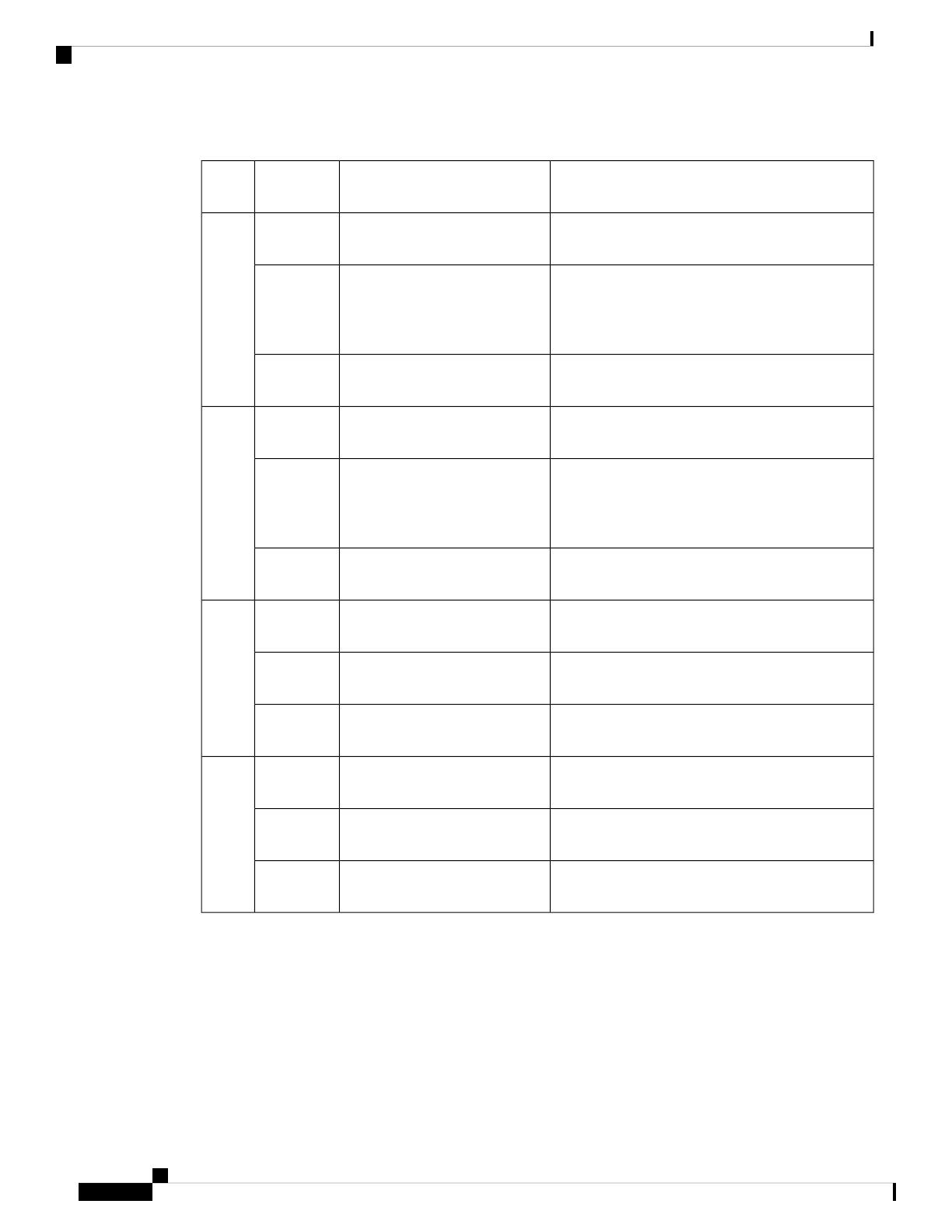
RF Band Mapping for Antenna Ports:
RXTXTechnologyAntenna
Port
B1, B2, B3, B4, B5, B6, B8, B9, B19B1, B2, B3, B4, B5, B6, B8, B9,
B19
3G
WDCMA
ANT 0
B1, B2, B3, B4, B5, B7, B8, B12, B13, B14, B17,
B18, B19, B20, B25, B26, B28, B29, B30, B32,
B34, B38, B39, B40, B41, B42, B43, B46, B48,
B66, B71
B1, B2, B3, B4, B5, B7, B8,
B12, B13, B14, B17, B18, B19,
B20, B25, B26, B28, B30, B34,
B38, B39, B40, B41, B66, B71
LTE
n1, n2, n3, n5, n7, n8, n12, n20, n25, n28, n38, n40,
n41, n48, n66, n71, n77, n78, n79
n1, n2, n3, n5, n7, n8, n12, n20,
n28, n38, n40, n41, n66, n71
5G NR FR1
B1, B2, B3, B4, B5, B6, B8, B9, B19
-3G
WDCMA
ANT 1
B1, B2, B3, B4, B5, B7, B8, B12, B13, B14, B17,
B18, B19, B20, B25, B26, B28, B29, B30, B32,
B34, B38, B39, B40, B41, B42, B43, B46, B48,
B66, B71
B5, B20, B42, B43, B48, B71LTE
n1, n2, n3, n5, n7, n8, n12, n20, n25, n28, n38, n40,
n41, n48, n66, n71, n77, n78, n79
n5, n48, n77, n78, n795G NR FR1
-
-3G
WDCMA
ANT 2
B1, B2, B3, B4, B7, B25, B30, B32, B34, B38, B39,
B40, B41, B42, B43, B46, B48, B66
B1, B2, B3, B4, B7, B41, B66LTE
n1, n2, n3, n7, n25, n38, n40, n41, n48, n66, n77,
n78, n79
n1, n2, n3, n7, n25, n41, n66,
n77, n78, n79
5G NR FR1
-
-3G
WDCMA
ANT 3
B1, B2, B3, B4, B7, B25, B30, B32, B34, B38, B39,
B40, B41, B42, B43, B46, B48, B66
-LTE
n1, n2, n3, n7, n25, n38, n40, n41, n48, n66, n77,
n78, n79
-5G NR FR1
Attaching the Antennas
To attach the antenna in the Pluggable Interface Module, perform the below steps:
Cisco Catalyst Pluggable Interface Module
6
Cisco Catalyst Pluggable Interface Module
Attaching the Antennas
Figure 4: Attaching 5G NR Antenna (5G-ANTM-O4-B) to P-5GS6-GL PIM
5G NR Antenna (5G-ANTM-04-B) is supported on both P-LTEAP18-GL and P-5GS6-GL PIMs.
Note
1. Attach each SMA cable to the ports as indicated in the table mappings.
2. Ensure that you tighten and secure each SMA cable into the SMA connector on the PIM.
Cisco Catalyst Pluggable Interface Module
7
Cisco Catalyst Pluggable Interface Module
Attaching the Antennas
Table 1: Port Mappings for 5G-ANTM-0-4-B on P-5GS6-GL and P-LTEAP18-GL PIMs
P-5GS6-GLP-LTEAP18-GL5G-ANTM-O-4-B
ANT 0Main 0MAIN 0
(LTE1)
ANT 1Main 1MAIN 1
(LTE3)
ANT 2DIV 0DIV 0 (LTE2)
ANT 3DIV 1DIV 1 (LTE4)
GPSNo
connection
GNSS
The following link contains the antenna specifications and installation instructions for 5G NR
(5G-ANTM-O-4-B):
https://www.cisco.com/c/en/us/td/docs/routers/connectedgrid/antennas/installing-combined/
b-cisco-industrial-routers-and-industrial-wireless-access-points-antenna-guide/m-5g-antm-04b.html#Cisco_
Generic_Topic.dita_e780a6fe-fa46-4a00-bd9d-1c6a98b7bcb9
Cisco Catalyst Pluggable Interface Module
8
Cisco Catalyst Pluggable Interface Module
Attaching the Antennas
  • Page 1 1
  • Page 2 2
  • Page 3 3
  • Page 4 4
  • Page 5 5
  • Page 6 6
  • Page 7 7
  • Page 8 8

Cisco Catalyst Pluggable Interface Module Owner's manual

Type
Owner's manual

Cisco Catalyst Pluggable Interface Module offers flexibility and scalability for your network. It enables you to add new interfaces or replace existing ones without disrupting your network operations. With support for various interface types, including Ethernet, serial, and wireless, this module provides versatile connectivity options. It's ideal for expanding the capabilities of your network devices, such as routers and switches, to meet evolving business needs and accommodate new technologies.

Ask a question and I''ll find the answer in the document

Finding information in a document is now easier with AI