Page is loading ...

INSTALLATION INSTRUCTIONS FOR PART 95-5000
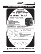
95-5000B
95-5000S
KIT FEATURES
•Double DIN Radio Provision
•Stacked ISO Mount Units Provision
•Painted ToMatchFactoryDash:
95-5000B = BLACK
95-5000S = SILVER
•A) Radio Housing • B) Radio Housing Brackets
KIT COMPONENTS
A
•Phillips Screwdriver
•Small Flat Blade Screwdriver/ Panel Removal Tool
1-800-221-0932
©COPYRIGHT 2008 METRA ELECTRONICS CORPORATION
www.metraonline.com
TOOLS REQUIRED:
APPLICATIONS
LINCOLN LS 2000-2006
FORD Thunderbird 2002-2005
B

Dash Disassembly
-LINCOLN LS 2000-2006/LINCOLN Thunderbird 2002-2005 . . . . . . . . . . . . 1,2
Kit Assembly
-Double DIN Radio Provision/Stacked ISO Mount Units Provision . . . . . . . . . 3
Final Assembly ..........................................4
TABLE OF CONTENTS
95-5000
*Note:
Refer also to the instructions included with the aftermarket radio.
K
NOWLEDGE IS
P
OWER
Enhanceyour installation and fabrication skillsby
enrolling in the most recognizedandrespected
mobile electronics school in our industry.
Log onto www.installerinstitute.comor call
800-354-6782 for more informationandtake
steps towardabetter tomorrow.

95-5000 DASH DISASSEMBLY
LINCOLN LS 2000-2006
FORD THUNDERBIRD 2002-2005
1
Disconnect the negative battery ter-
minal to prevent an accidental short
circuit.
1
Unclip and remove the A/C vent panel.
(Figure A)
2
Remove (2) 10 MM bolts exposed
behind vent panel from top of radio
brackets.
(Figure B)
3
Unclip and remove the panel
surrounding the ashtray.
(Figure C)
4
Continued on page 2.
A
C
B

95-5000 DASH DISASSEMBLY
LINCOLN LS 2000-2006
FORD THUNDERBIRD 2002-2005
2
2 SCREWS
FROM EACH
SIDE
Remove (2) Phillips screws exposed
behind panel then remove the ashtray
assembly.
(Figure D)
5
Remove (2) 10 MM bolts from inside
ashtray cavity from bottom of radio
brackets.
(Figure E)
6
Unplug and remove radio/climate
control assembly from dash then
remove (4) Phillips screws securing
the climate controls to the assembly.
(Retain the (4) Phillips screws and
climate controls for re-installation)
(Figure F)
7
Continue to kit assembly.
D
F
E

3
95-5000 KIT ASSEMBLY
B
C
A
DOUBLE DIN/STACKED ISO MOUNT UNITS PROVISION
Mount the climate control into the
radio housing brackets. (
Figure A)
1
Attach the radio housing to the
radio/climate control assembly.
(
Figure C)
3
Mount the Double DIN/ Stacked ISO
mount unit(s) into the radio housing
bracket/climate control assembly
using screws supplied with the unit(s).
(Figure B)
2
Continue to final assembly.
*Note: Refer also to the instructions included with the aftermarket radio.

95-5000 FINAL ASSEMBLY
FINAL ASSEMBLY
(A) Strip wire ends back 1/2"
(B)Twist ends together
(C)Solder
(D)Tape
A
B
C
D
Locate the factory wiring harness in the dash. Metra recommends using the
proper mating adapter and making connections as shown. (Isolate and individ-
ually tape off the ends of any unused wires to prevent electrical short circuit.)
Re-connect the negative battery terminal and test the unit for proper operation.
Reassemble radio and dash assemblies in reverse order of disassembly.
1
2
3
4
FINAL WIRING CONNECTIONS
Make wiring connections using the EIA color code chart shown below and the instructions included with the
head unit. Metra recommends making connections as shown below; Strip, Splice, Solder, Tape. Isolate and
individually tape off ends of any unused wires to prevent electrical short circuit.
METRA / EIA WIRING CODE
12V Ignition / Acc..........Red
12V Batt / Memory. . . . . . . . . Yellow
Ground. . . . . . . . . . . . . . . . . . Black*
Power Antenna. . . . . . . . . . . . Blue
Amp Turn-On . . . . . . . . . . . . . Blue / White
Amp Ground. . . . . . . . . . . . . . Black / White
Illumination . . . . . . . . . . . . . . Orange
Dimmer . . . . . . . . . . . . . . . . . Orange / White
Right Front (+) . . . . . . . . . . . . Gray
Right Front (-). . . . . . . . . . . . . Gray/ Black
Left Front (+) . . . . . . . . . . . . . White
Left Front (-). . . . . . . . . . . . . . White / Black
Right Rear (+) . . . . . . . . . . . . Violet
Right Rear (-) . . . . . . . . . . . . . Violet / Black
Left Rear (+) .............Green
Left Rear (-) . . . . . . . . . . . . . . Green / Black
*NOTE: When a Black wire is not present, ground radio to vehicle chassis.
All colors may not be present on all leads due to manufacturer’s specifications.
Enjoyyour newly installed radio!

95-5000 INSTRUCTIONS
1-800-221-0932
REV.12/16/08 © COPYRIGHT 2008 METRA ELECTRONICS CORPORATION INST95-5000
www.metraonline.com
/