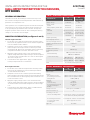
Honeywell 32307666 Hall-effect rotary position sensors provide non-contact sensing in harsh environments with a competitive cost. These sensors use a magnetically biased, Hall-effect integrated circuit (IC) to sense rotary movement over a set operating range. They are suitable for various applications, including transportation and industrial machinery.
Honeywell 32307666 Hall-effect rotary position sensors provide non-contact sensing in harsh environments with a competitive cost. These sensors use a magnetically biased, Hall-effect integrated circuit (IC) to sense rotary movement over a set operating range. They are suitable for various applications, including transportation and industrial machinery.


-
 1
1
-
 2
2
-
 3
3
-
 4
4
-
 5
5


Honeywell 32307666 Hall-effect rotary position sensors provide non-contact sensing in harsh environments with a competitive cost. These sensors use a magnetically biased, Hall-effect integrated circuit (IC) to sense rotary movement over a set operating range. They are suitable for various applications, including transportation and industrial machinery.
Ask a question and I''ll find the answer in the document
Finding information in a document is now easier with AI
Related papers
-
Honeywell 32307666RTP Series Hall-effect Rotary Position Sensors Installation guide
-
-
-
Honeywell 50069443 User manual
-
Honeywell V19 User manual
-
-
-
-
-
