Wireless actuator
4-channel impulse switch with
integrated relay function
FSR71NP-4x-230V
GB
Temperature at mounting location:
-20°C up to +50°C.
Storage temperature: -25°C up to +70°C.
Relative humidity:
annual average value <75%.
30 400 865 - 5
Only skilled electricians may install this
electrical equipment otherwise there is
the risk of re or electric shock!
valid for devices from production week
07/22 (see bottom side of housing)
Frequency 868.3 MHz
Transmit power max. 10 mW
Hereby, Eltako GmbH declares that the radio
equipment type FSR71NP-4x-230V is in
com pliance with Directive 2014/53/EU.
The full text of the EU declaration of
conformity is available at the following
internet address: eltako.com
Must be kept for later use!
Eltako GmbH
D-70736 Fellbach
Technical Support English:
+49 711 94350025
technical-support@eltako.de
eltako.com
03/2022 Subject to change without notice.
4-channel impulse switch with integrated
relay function, 1 NO contact each not
potential free 4 A/250 V AC. 230 V LED
lamps up to 400 W, incandescent lamps
1000 watts. With light scene control by PC
or wireless push buttons. Encrypted wire-
less, bidirectional wireless and repeater
function are switchable. Only 0.8 watt
standby loss.
Mounting in the 230 V power supply cord, e.g.
in false ceilings and lamps. 166 mm long,
46 mm wide and 31 mm high.
If supply voltage fails, the switching state is
retained.
The channels can be taught-in as ES and/or
ER channel separately from each other.
Scene control:
Several channels of one or several FSR71NP-4x
devices can be switched on or off in a scene
by one of the four signals of a pushbutton
with double rocker taught-in as a scene
button.
Central commands on PC are sent using the
Wireless Building Visualisation and Control
Software GFVS. To do this, teach-in one or
several FSR71NP-4x devices.
Encrypted sensors can be taught in.
You can switch on bidirectional wireless and/
or a repeater function.
Every change in state and incoming central
command telegrams are conrmed by a
wireless telegram. This wireless tele gram
can be taught-in in other actuators, in uni-
versal displays FUA55 and in the GFVS soft-
ware.
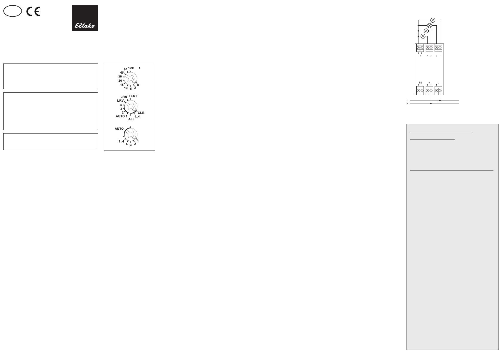
Function rotary switches
Use the rotary switches to teach-in the
pushbuttons and test the 4 channels as
required. For normal mode, the middle and
lower rotary switches are then set to AUTO.
With the upper rotary switch the EW time
(0-120 seconds) is directly set for relays or
the RV time (0-120 minutes) for impulse
switches for all channels if necessary.
When FBH wireless motion/brightness
sensors (masters) are taught-in, the switch-
ing threshold is dened separately for each
channel using the upper rotary switch. The
switching threshold switches the lighting on
or off depending on the brightness (in addi-
tion to motion) (from approx. 30lux in posi-
tion 0 to approx. 0 300lux in position 90).
If FBH devices (slaves) are taught-in in
Position 120, they are only evaluated as
motion detectors. Several FBH devices are
interlinked per channel. If an FBH signals
'motion', the NO contact closes. Only when all
FBH devices signal 'no motion' does the NO
contact open after the preset RV time. When
an FBH is taught-in, the RV time only applies
to the FBH.
Press the ON side of a direction pushbutton
for 2 seconds to switch it on permanently.
Signals are not evaluated by the FBH. Press
the OFF side of a direction pushbutton for 2
seconds to switch it off permanently. Signals
are not evaluated by the FBH. Press the
direction pushbutton briey to re-evaluate
FBH signals.
Semi-automatic motion detection with
taught-in FB65B wireless motion sensor
(factory setting): Press the pushbutton to
switch on. This starts a release delay time of
5 minutes during which the device switches
on again if motion is detected. When no fur-
ther motion is detected, the device switches
off automatically after 5 minutes in addition
to the set RV time. The actuator then re-
sponds to motion for a further 5 minutes
before switching off automatically. After this
time expires, the device must be switched on
again by pressing the pushbutton. You can
switch the device off at any time by pressing
the pushbutton. Motion is then no longer
evaluated.
Fully automatic motion detection with
taught-in FB65B wireless motion sensor:
If the actuator is not to switch on automati-
cally when motion is detected, e.g. in rooms
without daylight, replug the jumper to ‚ac-
tive‘ on the FB65B device. When no further
motion is detected, the device switches off
automatically after a release delay time of
5 minutes in addition to the set RV time.
Press the pushbutton at any time to switch
the device on or off. When motion is detected,
the device switches on again automatically.
When wireless brightness sensors FAH60
are taught-in, dene the switching threshold
separately for each channel using the top
rotary switch. The switching threshold
switches the lighting on or off depending on
the brightness (from approx. 0lux in positi on
0 to approx. 50lux in position 120). A hysteresis
of approx. 300lux is permanently set for
switch on/off. An additionally set RV time is
not taken into account.
Only one FBH (masters) or FAH is taught-in
per channel. However, one FBH (masters) or
FAH can be taught-in in several channels.
When wireless window/door contacts FTK
oder Hoppe window handles are taught-in,
different functions can be set with the middle
rotary switch in position AUTO 1 to AUTO 4
and linked to maximum 116 FTKs: AUTO 1 =
window closed then output active. AUTO 2 =
window open then output active. In settings
AUTO 3 and AUTO 4 the FTKs taught-in to a
single channel are linked automatically. With
AUTO 3 all FTKs must be closed so that the
NO contact closes (e.g. for climate control).
With AUTO 4 one open FTK is sucient to
close the NO contact (e.g. for an alarm signal
or to switch on the power supply for an
extractor hood). One or several FTKs can be
taught-in in several channels to allow several
simultaneous functions in each FTK. After a
power failure the link is restored by a new
signal to the FTK and a signal on the next
status message 15 minutes later. An addition-
ally set RV time is not taken into account.
When FRW wireless smoke alarms are
taught-in, they are interlinked per channel.
When an FRW signals 'smoke', the NO contact
closes. Only after all FRW devices signal ‘no
smoke’ does the NO contact open.
When water probes are taught-in, a variety
of functions can be set using the middle
rotary switch in positions AUTO 1 to AUTO 4.
AUTO 1 = 'no water', then NO contact closed.
AUTO 2 = 'water', then NO contact closed.
In Positions AUTO 3 and AUTO 4 the water
probes taught-in to a single channel are
interlinked automatically. With AUTO 3, all
water probes must signal 'no water' before
the NO contact closes. The NO contact opens
when a water probe signals 'water'. With
AUTO 4, the NO contact closes when a water
probe signals 'water'. Only when all water
probes signal 'no water' does the NO contact
open. An additionally set RV time is ignored.
The red LED accompanies the teach-in
process and indicates control commands in
operation by ashing briey.
The green LED ashes briey when a
conrmation telegram is sent.
Typical connection
Teaching-in wireless sensors
in wireless actuators
All sensors must be taught-in in the
actuators so that they can detect and
execute commands.
Teaching-in actuator FSR71NP-4x-230V
The teach-in memory is empty on delivery
from the factory. If you are unsure wheth-
er the teach-in memory contains some-
thing or not, you must rst clear the
memory contents completely:
Set the middle rotary switch to ALL. The
LED ashes at a high rate. Within the next
10 seconds, turn the upper rotary switch
three times to the right stop (turn clock-
wise) and then turn back away from the
stop. The LED stops ashing and goes out
after 2 seconds. All taught-in sensors are
cleared.
Clear individual taught-in sensors
in the same way as in the teach-in
procedure, except that you set the middle
rotary switch to CLR instead of LRN, and
operate the sensor. The LED previously
ashing at a high rate goes out.
Clear device conguration:
Set the middle rotary switch to ALL. The
red LED ashes at a high rate. Within the
next 10 seconds, turn the upper rotary
switch six times to the left stop (turn anti-
clockwise) and away again. The red LED
stops ashing and goes out after 5 sec-
onds. The factory settings are restored.
Teaching-in sensors:
A total of 120 memory locations are
available.
1. Select the required channel 1, 2, 3, 4 or
1..4 using the lower rotary switch.
2. Use the upper rotary switch to select
the required teach-in function.
0 = teach in 'direction button';
Rocker is completely taught-in auto-
matically when operating the push-
button. The side on which the pushbut-
ton is rst operated is dened for
switching on, the other side for switch-
ing off.
5 = teach in 'universal push button ES';
10 = teach in 'universal push button ER';
15 = teach in ‘central control push-
button ON' with priority;
20 = teach in 'central control push-
button OFF' with priority;
Central push button have priority as
long as they are pressed.
30 = teach in 'scene button';
Scene push buttons (double rocker) are
taught-in in fully automatic mode. 'Save
scenes' as described further on.
45 = teach in 'central control button ON';
90 = teach in 'central control button OFF';
120 = teach in FBH (slave) and FRW;
With FTK, window handle, FB65B and
water probes, you need pay no attention
to the teach-in position of the upper rotary
switch.
With rotary switches and GFVS pay no
attention to the teach-in position. On
teach-in, conrmation telegrams are
switched on and sent automatically.
Teach in a wireless switch FS..
as a 'universal switch ES' (upper rotary
switch in position 5):
Press the wireless switch separately at
the top and bottom for teach in.
Function: press the wireless switch up or
down, each time it is pressed, the switch
position of the actuator changes (toggling).
If several wireles switches are taught in,
the wireless switch fullls the function of
a changeover switch.
3. Set the middle rotary switch to LRN.
The LED ashes at a low rate.
4. Press the sensor to be taught-in.
The LED goes out.
To teach-in further sensors, turn the middle
rotary switch briey away from position
LRN. Continue the procedure from pos 1.
After teaching, set the middle and
bottom rotary switch to AUTO and set the
top rotary switch to the desired time. For
taught-in window/door contacts FTK, note
the required setting AUTO 1 to 4 of the
middle rotary switch.
You can teach in unencrypted and
encrypted sensors.
Teach in encrypted sensors:
1. Set the middle rotary switch to LRV.
The red LED ashes at a high rate.
2. Within 120 seconds, enable sensor
encryption. The red LED goes out.
Caution: Do not switch off the power
supply.
3. Then teach in the encrypted sensor as
described in 'Teaching-in sensors'.
To teach in other encrypted sensors, turn
the middle rotary switch briey away from
position LRV and then turn it to 1.
With encrypted sensors, use the 'rolling
code', i.e. the code changes in each tele-
gram, both in the transmitter and in the
receiver.
If a sensor sends more than 50 telegrams
when the actuator is not enabled, the
sensor is no longer recognised by the
enabled actuator and you must repeat
teach-in as ‘encrypted sensor’. It is not
necessary to repeat the function teach-
in.
Teach in scenes
Up to 4 scenes are being saved with a
previously taught-in scene pushbutton.
1. All 4 channels of the impulse switch can
be turned on or off individually with a
previously taught-in universal-, direction-,
or central pushbutton as it is desired for
one scene.
2. The switch state is saved within 60 seconds
when you press one of the four rocker
ends of the doublerocker scene button
for longer than 3 seconds but shorter than
10 seconds.
3. If more scenes have to be saved return
back to point 1.
Recall scenes
Press one rocker of the scene pushbutton
briey to recall the scene you require. An
additionally set RV time is not taken into
account.
When the middle rotary switch is set to
TEST, the 4 contacts can be closed individu-
ally using the lower rotary switch:
TEST + AUTO = all contacts open,
TEST + 1 = contact 1 closed,
TEST + 2 = contact 2 closed,
TEST + 3 = contact 3 closed,
TEST + 4 = contact 4 closed,
TEST + 1..4 = all contacts closed.
Switch on repeater:
The repeater is switched off in the factory
setting. When disconnected, set the middle
rotary switch to CLR and the lower rotary
switch to the left stop (turning it counter-
clockwise. Switch on the power supply. The
red LED lights up to two seconds. The
repeater is switched on.
Switch off repeater:
When disconnected, set the middle rotary
switch to CLR and the lower rotary switch to
the right stop (turning it clockwise). Switch
on the power supply. The red LED lights up to
0.5 seconds. The repeater is switched off.
Switch-on conrmation telegrams:
For deliveries ex-works the conrmation
telegrams are switched-off. Set the lower
rotary switch to 1. Set the middle rotary
switch to CLR. The red LED ashes nervous-
ly. Now within 10 seconds turn the upper ro-
tary switch 3 times to the left (anticlockwise)
and then back away.
The red LED goes out and the green LED
lights up for 2 seconds. The conrmation
telegrams are switched-on.
Switch-off conrmation telegrams:
Set the lower rotary switch to 1. Set the mid-
dle rotary switch to CLR. The red LED ashes
nervously. Now within 10 seconds turn the
upper rotary switch 3 times to the left (anti-
clockwise) and then back away. The red LED
goes out immediately. The conrmation tele-
grams are switched-off.
Use the data transformer DAT71 to create a
link to a PC running the PCT14 software.
Congure FSR71:
The following points can be congured using
the PC PCT14 tool:
behavior upon return of supply voltage
teaching-in of wireless pushbuttons and
wireless Hoppe window handles with single
or double click
scenes for scene pushbuttons
add or change sensors
When an actuator is ready for
teach-in (the LED ashes at a low
rate), the very next incoming signal
is taught-in. Therefore, make
absolutely sure that you do not
activate any other sensors during
the teach-in phase.
Cable xation
The cable must be fastened with standard
cable ties (width <3,6mm).
!
Wireless actuator
4-channel impulse switch with
integrated relay function
FSR71NP-4x-230V
GB
Temperature at mounting location:
-20°C up to +50°C.
Storage temperature: -25°C up to +70°C.
Relative humidity:
annual average value <75%.
30 400 865 - 5
Only skilled electricians may install this
electrical equipment otherwise there is
the risk of re or electric shock!
valid for devices from production week
07/22 (see bottom side of housing)
Frequency 868.3 MHz
Transmit power max. 10 mW
Hereby, Eltako GmbH declares that the radio
equipment type FSR71NP-4x-230V is in
com pliance with Directive 2014/53/EU.
The full text of the EU declaration of
conformity is available at the following
internet address: eltako.com
Must be kept for later use!
Eltako GmbH
D-70736 Fellbach
Technical Support English:
+49 711 94350025
technical-support@eltako.de
eltako.com
03/2022 Subject to change without notice.
4-channel impulse switch with integrated
relay function, 1 NO contact each not
potential free 4 A/250 V AC. 230 V LED
lamps up to 400 W, incandescent lamps
1000 watts. With light scene control by PC
or wireless push buttons. Encrypted wire-
less, bidirectional wireless and repeater
function are switchable. Only 0.8 watt
standby loss.
Mounting in the 230 V power supply cord, e.g.
in false ceilings and lamps. 166 mm long,
46 mm wide and 31 mm high.
If supply voltage fails, the switching state is
retained.
The channels can be taught-in as ES and/or
ER channel separately from each other.
Scene control:
Several channels of one or several FSR71NP-4x
devices can be switched on or off in a scene
by one of the four signals of a pushbutton
with double rocker taught-in as a scene
button.
Central commands on PC are sent using the
Wireless Building Visualisation and Control
Software GFVS. To do this, teach-in one or
several FSR71NP-4x devices.
Encrypted sensors can be taught in.
You can switch on bidirectional wireless and/
or a repeater function.
Every change in state and incoming central
command telegrams are conrmed by a
wireless telegram. This wireless tele gram
can be taught-in in other actuators, in uni-
versal displays FUA55 and in the GFVS soft-
ware.
Function rotary switches
Use the rotary switches to teach-in the
pushbuttons and test the 4 channels as
required. For normal mode, the middle and
lower rotary switches are then set to AUTO.
With the upper rotary switch the EW time
(0-120 seconds) is directly set for relays or
the RV time (0-120 minutes) for impulse
switches for all channels if necessary.
When FBH wireless motion/brightness
sensors (masters) are taught-in, the switch-
ing threshold is dened separately for each
channel using the upper rotary switch. The
switching threshold switches the lighting on
or off depending on the brightness (in addi-
tion to motion) (from approx. 30lux in posi-
tion 0 to approx. 0 300lux in position 90).
If FBH devices (slaves) are taught-in in
Position 120, they are only evaluated as
motion detectors. Several FBH devices are
interlinked per channel. If an FBH signals
'motion', the NO contact closes. Only when all
FBH devices signal 'no motion' does the NO
contact open after the preset RV time. When
an FBH is taught-in, the RV time only applies
to the FBH.
Press the ON side of a direction pushbutton
for 2 seconds to switch it on permanently.
Signals are not evaluated by the FBH. Press
the OFF side of a direction pushbutton for 2
seconds to switch it off permanently. Signals
are not evaluated by the FBH. Press the
direction pushbutton briey to re-evaluate
FBH signals.
Semi-automatic motion detection with
taught-in FB65B wireless motion sensor
(factory setting): Press the pushbutton to
switch on. This starts a release delay time of
5 minutes during which the device switches
on again if motion is detected. When no fur-
ther motion is detected, the device switches
off automatically after 5 minutes in addition
to the set RV time. The actuator then re-
sponds to motion for a further 5 minutes
before switching off automatically. After this
time expires, the device must be switched on
again by pressing the pushbutton. You can
switch the device off at any time by pressing
the pushbutton. Motion is then no longer
evaluated.
Fully automatic motion detection with
taught-in FB65B wireless motion sensor:
If the actuator is not to switch on automati-
cally when motion is detected, e.g. in rooms
without daylight, replug the jumper to ‚ac-
tive‘ on the FB65B device. When no further
motion is detected, the device switches off
automatically after a release delay time of
5 minutes in addition to the set RV time.
Press the pushbutton at any time to switch
the device on or off. When motion is detected,
the device switches on again automatically.
When wireless brightness sensors FAH60
are taught-in, dene the switching threshold
separately for each channel using the top
rotary switch. The switching threshold
switches the lighting on or off depending on
the brightness (from approx. 0lux in positi on
0 to approx. 50lux in position 120). A hysteresis
of approx. 300lux is permanently set for
switch on/off. An additionally set RV time is
not taken into account.
Only one FBH (masters) or FAH is taught-in
per channel. However, one FBH (masters) or
FAH can be taught-in in several channels.
When wireless window/door contacts FTK
oder Hoppe window handles are taught-in,
different functions can be set with the middle
rotary switch in position AUTO 1 to AUTO 4
and linked to maximum 116 FTKs: AUTO 1 =
window closed then output active. AUTO 2 =
window open then output active. In settings
AUTO 3 and AUTO 4 the FTKs taught-in to a
single channel are linked automatically. With
AUTO 3 all FTKs must be closed so that the
NO contact closes (e.g. for climate control).
With AUTO 4 one open FTK is sucient to
close the NO contact (e.g. for an alarm signal
or to switch on the power supply for an
extractor hood). One or several FTKs can be
taught-in in several channels to allow several
simultaneous functions in each FTK. After a
power failure the link is restored by a new
signal to the FTK and a signal on the next
status message 15 minutes later. An addition-
ally set RV time is not taken into account.
When FRW wireless smoke alarms are
taught-in, they are interlinked per channel.
When an FRW signals 'smoke', the NO contact
closes. Only after all FRW devices signal ‘no
smoke’ does the NO contact open.
When water probes are taught-in, a variety
of functions can be set using the middle
rotary switch in positions AUTO 1 to AUTO 4.
AUTO 1 = 'no water', then NO contact closed.
AUTO 2 = 'water', then NO contact closed.
In Positions AUTO 3 and AUTO 4 the water
probes taught-in to a single channel are
interlinked automatically. With AUTO 3, all
water probes must signal 'no water' before
the NO contact closes. The NO contact opens
when a water probe signals 'water'. With
AUTO 4, the NO contact closes when a water
probe signals 'water'. Only when all water
probes signal 'no water' does the NO contact
open. An additionally set RV time is ignored.
The red LED accompanies the teach-in
process and indicates control commands in
operation by ashing briey.
The green LED ashes briey when a
conrmation telegram is sent.
Typical connection
Teaching-in wireless sensors
in wireless actuators
All sensors must be taught-in in the
actuators so that they can detect and
execute commands.
Teaching-in actuator FSR71NP-4x-230V
The teach-in memory is empty on delivery
from the factory. If you are unsure wheth-
er the teach-in memory contains some-
thing or not, you must rst clear the
memory contents completely:
Set the middle rotary switch to ALL. The
LED ashes at a high rate. Within the next
10 seconds, turn the upper rotary switch
three times to the right stop (turn clock-
wise) and then turn back away from the
stop. The LED stops ashing and goes out
after 2 seconds. All taught-in sensors are
cleared.
Clear individual taught-in sensors
in the same way as in the teach-in
procedure, except that you set the middle
rotary switch to CLR instead of LRN, and
operate the sensor. The LED previously
ashing at a high rate goes out.
Clear device conguration:
Set the middle rotary switch to ALL. The
red LED ashes at a high rate. Within the
next 10 seconds, turn the upper rotary
switch six times to the left stop (turn anti-
clockwise) and away again. The red LED
stops ashing and goes out after 5 sec-
onds. The factory settings are restored.
Teaching-in sensors:
A total of 120 memory locations are
available.
1. Select the required channel 1, 2, 3, 4 or
1..4 using the lower rotary switch.
2. Use the upper rotary switch to select
the required teach-in function.
0 = teach in 'direction button';
Rocker is completely taught-in auto-
matically when operating the push-
button. The side on which the pushbut-
ton is rst operated is dened for
switching on, the other side for switch-
ing off.
5 = teach in 'universal push button ES';
10 = teach in 'universal push button ER';
15 = teach in ‘central control push-
button ON' with priority;
20 = teach in 'central control push-
button OFF' with priority;
Central push button have priority as
long as they are pressed.
30 = teach in 'scene button';
Scene push buttons (double rocker) are
taught-in in fully automatic mode. 'Save
scenes' as described further on.
45 = teach in 'central control button ON';
90 = teach in 'central control button OFF';
120 = teach in FBH (slave) and FRW;
With FTK, window handle, FB65B and
water probes, you need pay no attention
to the teach-in position of the upper rotary
switch.
With rotary switches and GFVS pay no
attention to the teach-in position. On
teach-in, conrmation telegrams are
switched on and sent automatically.
Teach in a wireless switch FS..
as a 'universal switch ES' (upper rotary
switch in position 5):
Press the wireless switch separately at
the top and bottom for teach in.
Function: press the wireless switch up or
down, each time it is pressed, the switch
position of the actuator changes (toggling).
If several wireles switches are taught in,
the wireless switch fullls the function of
a changeover switch.
3. Set the middle rotary switch to LRN.
The LED ashes at a low rate.
4. Press the sensor to be taught-in.
The LED goes out.
To teach-in further sensors, turn the middle
rotary switch briey away from position
LRN. Continue the procedure from pos 1.
After teaching, set the middle and
bottom rotary switch to AUTO and set the
top rotary switch to the desired time. For
taught-in window/door contacts FTK, note
the required setting AUTO 1 to 4 of the
middle rotary switch.
You can teach in unencrypted and
encrypted sensors.
Teach in encrypted sensors:
1. Set the middle rotary switch to LRV.
The red LED ashes at a high rate.
2. Within 120 seconds, enable sensor
encryption. The red LED goes out.
Caution: Do not switch off the power
supply.
3. Then teach in the encrypted sensor as
described in 'Teaching-in sensors'.
To teach in other encrypted sensors, turn
the middle rotary switch briey away from
position LRV and then turn it to 1.
With encrypted sensors, use the 'rolling
code', i.e. the code changes in each tele-
gram, both in the transmitter and in the
receiver.
If a sensor sends more than 50 telegrams
when the actuator is not enabled, the
sensor is no longer recognised by the
enabled actuator and you must repeat
teach-in as ‘encrypted sensor’. It is not
necessary to repeat the function teach-
in.
Teach in scenes
Up to 4 scenes are being saved with a
previously taught-in scene pushbutton.
1. All 4 channels of the impulse switch can
be turned on or off individually with a
previously taught-in universal-, direction-,
or central pushbutton as it is desired for
one scene.
2. The switch state is saved within 60 seconds
when you press one of the four rocker
ends of the doublerocker scene button
for longer than 3 seconds but shorter than
10 seconds.
3. If more scenes have to be saved return
back to point 1.
Recall scenes
Press one rocker of the scene pushbutton
briey to recall the scene you require. An
additionally set RV time is not taken into
account.
When the middle rotary switch is set to
TEST, the 4 contacts can be closed individu-
ally using the lower rotary switch:
TEST + AUTO = all contacts open,
TEST + 1 = contact 1 closed,
TEST + 2 = contact 2 closed,
TEST + 3 = contact 3 closed,
TEST + 4 = contact 4 closed,
TEST + 1..4 = all contacts closed.
Switch on repeater:
The repeater is switched off in the factory
setting. When disconnected, set the middle
rotary switch to CLR and the lower rotary
switch to the left stop (turning it counter-
clockwise. Switch on the power supply. The
red LED lights up to two seconds. The
repeater is switched on.
Switch off repeater:
When disconnected, set the middle rotary
switch to CLR and the lower rotary switch to
the right stop (turning it clockwise). Switch
on the power supply. The red LED lights up to
0.5 seconds. The repeater is switched off.
Switch-on conrmation telegrams:
For deliveries ex-works the conrmation
telegrams are switched-off. Set the lower
rotary switch to 1. Set the middle rotary
switch to CLR. The red LED ashes nervous-
ly. Now within 10 seconds turn the upper ro-
tary switch 3 times to the left (anticlockwise)
and then back away.
The red LED goes out and the green LED
lights up for 2 seconds. The conrmation
telegrams are switched-on.
Switch-off conrmation telegrams:
Set the lower rotary switch to 1. Set the mid-
dle rotary switch to CLR. The red LED ashes
nervously. Now within 10 seconds turn the
upper rotary switch 3 times to the left (anti-
clockwise) and then back away. The red LED
goes out immediately. The conrmation tele-
grams are switched-off.
Use the data transformer DAT71 to create a
link to a PC running the PCT14 software.
Congure FSR71:
The following points can be congured using
the PC PCT14 tool:
behavior upon return of supply voltage
teaching-in of wireless pushbuttons and
wireless Hoppe window handles with single
or double click
scenes for scene pushbuttons
add or change sensors
When an actuator is ready for
teach-in (the LED ashes at a low
rate), the very next incoming signal
is taught-in. Therefore, make
absolutely sure that you do not
activate any other sensors during
the teach-in phase.
Cable xation
The cable must be fastened with standard
cable ties (width <3,6mm).
!
Wireless actuator
4-channel impulse switch with
integrated relay function
FSR71NP-4x-230V
GB
Temperature at mounting location:
-20°C up to +50°C.
Storage temperature: -25°C up to +70°C.
Relative humidity:
annual average value <75%.
30 400 865 - 5
Only skilled electricians may install this
electrical equipment otherwise there is
the risk of re or electric shock!
valid for devices from production week
07/22 (see bottom side of housing)
Frequency 868.3 MHz
Transmit power max. 10 mW
Hereby, Eltako GmbH declares that the radio
equipment type FSR71NP-4x-230V is in
com pliance with Directive 2014/53/EU.
The full text of the EU declaration of
conformity is available at the following
internet address: eltako.com
Must be kept for later use!
Eltako GmbH
D-70736 Fellbach
Technical Support English:
+49 711 94350025
eltako.com
03/2022 Subject to change without notice.
4-channel impulse switch with integrated
relay function, 1 NO contact each not
potential free 4 A/250 V AC. 230 V LED
lamps up to 400 W, incandescent lamps
1000 watts. With light scene control by PC
or wireless push buttons. Encrypted wire-
less, bidirectional wireless and repeater
function are switchable. Only 0.8 watt
standby loss.
Mounting in the 230 V power supply cord, e.g.
in false ceilings and lamps. 166 mm long,
46 mm wide and 31 mm high.
If supply voltage fails, the switching state is
retained.
The channels can be taught-in as ES and/or
ER channel separately from each other.
Scene control:
Several channels of one or several FSR71NP-4x
devices can be switched on or off in a scene
by one of the four signals of a pushbutton
with double rocker taught-in as a scene
button.
Central commands on PC are sent using the
Wireless Building Visualisation and Control
Software GFVS. To do this, teach-in one or
several FSR71NP-4x devices.
Encrypted sensors can be taught in.
You can switch on bidirectional wireless and/
or a repeater function.
Every change in state and incoming central
command telegrams are conrmed by a
wireless telegram. This wireless tele gram
can be taught-in in other actuators, in uni-
versal displays FUA55 and in the GFVS soft-
ware.
Function rotary switches
Use the rotary switches to teach-in the
pushbuttons and test the 4 channels as
required. For normal mode, the middle and
lower rotary switches are then set to AUTO.
With the upper rotary switch the EW time
(0-120 seconds) is directly set for relays or
the RV time (0-120 minutes) for impulse
switches for all channels if necessary.
When FBH wireless motion/brightness
sensors (masters) are taught-in, the switch-
ing threshold is dened separately for each
channel using the upper rotary switch. The
switching threshold switches the lighting on
or off depending on the brightness (in addi-
tion to motion) (from approx. 30lux in posi-
tion 0 to approx. 0 300lux in position 90).
If FBH devices (slaves) are taught-in in
Position 120, they are only evaluated as
motion detectors. Several FBH devices are
interlinked per channel. If an FBH signals
'motion', the NO contact closes. Only when all
FBH devices signal 'no motion' does the NO
contact open after the preset RV time. When
an FBH is taught-in, the RV time only applies
to the FBH.
Press the ON side of a direction pushbutton
for 2 seconds to switch it on permanently.
Signals are not evaluated by the FBH. Press
the OFF side of a direction pushbutton for 2
seconds to switch it off permanently. Signals
are not evaluated by the FBH. Press the
direction pushbutton briey to re-evaluate
FBH signals.
Semi-automatic motion detection with
taught-in FB65B wireless motion sensor
(factory setting): Press the pushbutton to
switch on. This starts a release delay time of
5 minutes during which the device switches
on again if motion is detected. When no fur-
ther motion is detected, the device switches
off automatically after 5 minutes in addition
to the set RV time. The actuator then re-
sponds to motion for a further 5 minutes
before switching off automatically. After this
time expires, the device must be switched on
again by pressing the pushbutton. You can
switch the device off at any time by pressing
the pushbutton. Motion is then no longer
evaluated.
Fully automatic motion detection with
taught-in FB65B wireless motion sensor:
If the actuator is not to switch on automati-
cally when motion is detected, e.g. in rooms
without daylight, replug the jumper to ‚ac-
tive‘ on the FB65B device. When no further
motion is detected, the device switches off
automatically after a release delay time of
5 minutes in addition to the set RV time.
Press the pushbutton at any time to switch
the device on or off. When motion is detected,
the device switches on again automatically.
When wireless brightness sensors FAH60
are taught-in, dene the switching threshold
separately for each channel using the top
rotary switch. The switching threshold
switches the lighting on or off depending on
the brightness (from approx. 0lux in positi on
0 to approx. 50lux in position 120). A hysteresis
of approx. 300lux is permanently set for
switch on/off. An additionally set RV time is
not taken into account.
Only one FBH (masters) or FAH is taught-in
per channel. However, one FBH (masters) or
FAH can be taught-in in several channels.
When wireless window/door contacts FTK
oder Hoppe window handles are taught-in,
different functions can be set with the middle
rotary switch in position AUTO 1 to AUTO 4
and linked to maximum 116 FTKs: AUTO 1 =
window closed then output active. AUTO 2 =
window open then output active. In settings
AUTO 3 and AUTO 4 the FTKs taught-in to a
single channel are linked automatically. With
AUTO 3 all FTKs must be closed so that the
NO contact closes (e.g. for climate control).
With AUTO 4 one open FTK is sucient to
close the NO contact (e.g. for an alarm signal
or to switch on the power supply for an
extractor hood). One or several FTKs can be
taught-in in several channels to allow several
simultaneous functions in each FTK. After a
power failure the link is restored by a new
signal to the FTK and a signal on the next
status message 15 minutes later. An addition-
ally set RV time is not taken into account.
When FRW wireless smoke alarms are
taught-in, they are interlinked per channel.
When an FRW signals 'smoke', the NO contact
closes. Only after all FRW devices signal ‘no
smoke’ does the NO contact open.
When water probes are taught-in, a variety
of functions can be set using the middle
rotary switch in positions AUTO 1 to AUTO 4.
AUTO 1 = 'no water', then NO contact closed.
AUTO 2 = 'water', then NO contact closed.
In Positions AUTO 3 and AUTO 4 the water
probes taught-in to a single channel are
interlinked automatically. With AUTO 3, all
water probes must signal 'no water' before
the NO contact closes. The NO contact opens
when a water probe signals 'water'. With
AUTO 4, the NO contact closes when a water
probe signals 'water'. Only when all water
probes signal 'no water' does the NO contact
open. An additionally set RV time is ignored.
The red LED accompanies the teach-in
process and indicates control commands in
operation by ashing briey.
The green LED ashes briey when a
conrmation telegram is sent.
Typical connection
Teaching-in wireless sensors
in wireless actuators
All sensors must be taught-in in the
actuators so that they can detect and
execute commands.
Teaching-in actuator FSR71NP-4x-230V
The teach-in memory is empty on delivery
from the factory. If you are unsure wheth-
er the teach-in memory contains some-
thing or not, you must rst clear the
memory contents completely:
Set the middle rotary switch to ALL. The
LED ashes at a high rate. Within the next
10 seconds, turn the upper rotary switch
three times to the right stop (turn clock-
wise) and then turn back away from the
stop. The LED stops ashing and goes out
after 2 seconds. All taught-in sensors are
cleared.
Clear individual taught-in sensors
in the same way as in the teach-in
procedure, except that you set the middle
rotary switch to CLR instead of LRN, and
operate the sensor. The LED previously
ashing at a high rate goes out.
Clear device conguration:
Set the middle rotary switch to ALL. The
red LED ashes at a high rate. Within the
next 10 seconds, turn the upper rotary
switch six times to the left stop (turn anti-
clockwise) and away again. The red LED
stops ashing and goes out after 5 sec-
onds. The factory settings are restored.
Teaching-in sensors:
A total of 120 memory locations are
available.
1. Select the required channel 1, 2, 3, 4 or
1..4 using the lower rotary switch.
2. Use the upper rotary switch to select
the required teach-in function.
0 = teach in 'direction button';
Rocker is completely taught-in auto-
matically when operating the push-
button. The side on which the pushbut-
ton is rst operated is dened for
switching on, the other side for switch-
ing off.
5 = teach in 'universal push button ES';
10 = teach in 'universal push button ER';
15 = teach in ‘central control push-
button ON' with priority;
20 = teach in 'central control push-
button OFF' with priority;
Central push button have priority as
long as they are pressed.
30 = teach in 'scene button';
Scene push buttons (double rocker) are
taught-in in fully automatic mode. 'Save
scenes' as described further on.
45 = teach in 'central control button ON';
90 = teach in 'central control button OFF';
120 = teach in FBH (slave) and FRW;
With FTK, window handle, FB65B and
water probes, you need pay no attention
to the teach-in position of the upper rotary
switch.
With rotary switches and GFVS pay no
attention to the teach-in position. On
teach-in, conrmation telegrams are
switched on and sent automatically.
Teach in a wireless switch FS..
as a 'universal switch ES' (upper rotary
switch in position 5):
Press the wireless switch separately at
the top and bottom for teach in.
Function: press the wireless switch up or
down, each time it is pressed, the switch
position of the actuator changes (toggling).
If several wireles switches are taught in,
the wireless switch fullls the function of
a changeover switch.
3. Set the middle rotary switch to LRN.
The LED ashes at a low rate.
4. Press the sensor to be taught-in.
The LED goes out.
To teach-in further sensors, turn the middle
rotary switch briey away from position
LRN. Continue the procedure from pos 1.
After teaching, set the middle and
bottom rotary switch to AUTO and set the
top rotary switch to the desired time. For
taught-in window/door contacts FTK, note
the required setting AUTO 1 to 4 of the
middle rotary switch.
You can teach in unencrypted and
encrypted sensors.
Teach in encrypted sensors:
1. Set the middle rotary switch to LRV.
The red LED ashes at a high rate.
2. Within 120 seconds, enable sensor
encryption. The red LED goes out.
Caution: Do not switch off the power
supply.
3. Then teach in the encrypted sensor as
described in 'Teaching-in sensors'.
To teach in other encrypted sensors, turn
the middle rotary switch briey away from
position LRV and then turn it to 1.
With encrypted sensors, use the 'rolling
code', i.e. the code changes in each tele-
gram, both in the transmitter and in the
receiver.
If a sensor sends more than 50 telegrams
when the actuator is not enabled, the
sensor is no longer recognised by the
enabled actuator and you must repeat
teach-in as ‘encrypted sensor’. It is not
necessary to repeat the function teach-
in.
Teach in scenes
Up to 4 scenes are being saved with a
previously taught-in scene pushbutton.
1. All 4 channels of the impulse switch can
be turned on or off individually with a
previously taught-in universal-, direction-,
or central pushbutton as it is desired for
one scene.
2. The switch state is saved within 60 seconds
when you press one of the four rocker
ends of the doublerocker scene button
for longer than 3 seconds but shorter than
10 seconds.
3. If more scenes have to be saved return
back to point 1.
Recall scenes
Press one rocker of the scene pushbutton
briey to recall the scene you require. An
additionally set RV time is not taken into
account.
When the middle rotary switch is set to
TEST, the 4 contacts can be closed individu-
ally using the lower rotary switch:
TEST + AUTO = all contacts open,
TEST + 1 = contact 1 closed,
TEST + 2 = contact 2 closed,
TEST + 3 = contact 3 closed,
TEST + 4 = contact 4 closed,
TEST + 1..4 = all contacts closed.
Switch on repeater:
The repeater is switched off in the factory
setting. When disconnected, set the middle
rotary switch to CLR and the lower rotary
switch to the left stop (turning it counter-
clockwise. Switch on the power supply. The
red LED lights up to two seconds. The
repeater is switched on.
Switch off repeater:
When disconnected, set the middle rotary
switch to CLR and the lower rotary switch to
the right stop (turning it clockwise). Switch
on the power supply. The red LED lights up to
0.5 seconds. The repeater is switched off.
Switch-on conrmation telegrams:
For deliveries ex-works the conrmation
telegrams are switched-off. Set the lower
rotary switch to 1. Set the middle rotary
switch to CLR. The red LED ashes nervous-
ly. Now within 10 seconds turn the upper ro-
tary switch 3 times to the left (anticlockwise)
and then back away.
The red LED goes out and the green LED
lights up for 2 seconds. The conrmation
telegrams are switched-on.
Switch-off conrmation telegrams:
Set the lower rotary switch to 1. Set the mid-
dle rotary switch to CLR. The red LED ashes
nervously. Now within 10 seconds turn the
upper rotary switch 3 times to the left (anti-
clockwise) and then back away. The red LED
goes out immediately. The conrmation tele-
grams are switched-off.
Use the data transformer DAT71 to create a
link to a PC running the PCT14 software.
Congure FSR71:
The following points can be congured using
the PC PCT14 tool:
behavior upon return of supply voltage
teaching-in of wireless pushbuttons and
wireless Hoppe window handles with single
or double click
scenes for scene pushbuttons
add or change sensors
When an actuator is ready for
teach-in (the LED ashes at a low
rate), the very next incoming signal
is taught-in. Therefore, make
absolutely sure that you do not
activate any other sensors during
the teach-in phase.
Cable xation
The cable must be fastened with standard
cable ties (width <3,6mm).
!

