Page is loading ...

5151 San Felipe Suite 500
Houston, TX 77056
www.goodmanmfg.com • www.amana-hac.com
© 2014 Goodman Manufacturing Company, L.P.
I
NSTALLATION
I
NSTRUCTIONS
FOR
*MVM97 & *CVM97
M
ODULATING
G
AS
F
URNACE
IOG-2007A
11/14
(Type FSP CATEGORY IV Direct
or Non Direct Vent Air Furnace)
These furnaces comply with requirements em-
bodied in the American National Standard / Na-
tional Standard of Canada ANSI Z21.47·CSA-2.3
Gas Fired Central Furnaces.
Installer:
Affix all manuals
adjacent to the unit.
As a professional installer you have an obligation to know
the product better than the customer. This includes all
safety precautions and related items.
Prior to actual installation, thoroughly familiarize yourself
with this Instruction Manual. Pay special attention to all
safety warnings. Often during installation or repair it is
possible to place yourself in a position which is more
hazardous than when the unit is in operation.
Remember, it is your responsibility to install the product
safely and to know it well enough to be able to instruct a
customer in its safe use.
Safety is a matter of common sense...a matter of thinking
before acting. Most dealers have a list of specific good
safety practices...follow them.
The precautions listed in this Installation Manual are
intended as supplemental to existing practices. However,
if there is a direct conflict between existing practices
and the content of this manual, the precautions listed
here take precedence.
RECOGNIZE THIS SYMBOL
AS A SAFETY PRECAUTION.
*NOTE: Please contact your distributor or our website for
the applicable Specification Sheet referred to in this manual.
TABLE OF CONTENTS
is a registered trademark of Maytag Corporation or its related companies and is used under license. All rights reserved.
SAFETY CONSIDERATIONS ......................................... 3
S
HIPPING INSPECTION ............................................ 4
ELECTROSTATIC DISCHARGE (ESD) PRECAUTIONS .................... 4
T
O THE INSTALLER ............................................. 5
PRODUCT DESCRIPTION ..................................... 5
F
EATURES ...................................................... 5
PRODUCT APPLICATION ..................................... 6
LOCATION REQUIREMENTS & CONSIDERATIONS ......... 7
CLEARANCES AND A CCESSIBILITY ................................... 8
E
XISTING FURNACE REMOVAL ..................................... 9
T
HERMOSTAT LOCATION ......................................... 10
COMBUSTION & VENTILATION AIR REQUIREMENTS ..... 10
INSTALLATION POSITIONS ................................. 14
HORIZONTAL APPLICATIONS & CONSIDERATIONS ...... 14
FURNACE SUSPENSION .......................................... 14
F
RONT COVER PRESSURE SWITCH TUBE LOCATION ................. 15
DRAIN TRAP AND LINES ......................................... 15
L
EVELING ..................................................... 15
A
LTERNATE ELECTRICAL AND GAS LINE CONNECTIONS .............. 15
DRAIN PAN .................................................... 15
FREEZE PROTECTION ............................................ 15
PROPANE GAS/HIGH ALTITUDE INSTALLATIONS ........ 15
VENT/FLUE PIPE & COMBUSTION AIR PIPE .............. 16
DUAL CERTIFICATION: NON-DIRECT/DIRECT VENT ................. 16
MATERIALS AND JOINING METHODS ............................... 16
PROPER VENT/FLUE AND COMBUSTION A IR PIPING PRACTICES ....... 17
TERMINATION LOCATIONS ........................................ 17
SPECIAL VENTING REQUIREMENTS FOR INSTALLATIONS IN CANADA .... 19
STANDARD FURNACE CONNECTIONS ............................... 19
COMBUSTION A IR PIPE .......................................... 19
VENT/INTAKE TERMINATIONS FOR INSTALLATION
OF
MULTIPLE DIRECT VENT FURNACES ....................... 23
CONCENTRIC VENT TERMINATION ................................. 23
SIDE WALL VENT KIT .......................................... 23
CONDENSATE DRAIN LINES & DRAIN TRAP .............. 23
GENERAL DRAIN INFORMATION ................................... 23
FIELD SUPPLIED DRAIN ......................................... 24
UPFLOW MODEL INSTALLED VERTICALLY .......................... 24
DRAIN EXITING RIGHT SIDE ...................................... 24
DRAIN EXITING LEFT SIDE ....................................... 24
UPFLOW MODEL INSTALLED HORIZONTALLY
WITH
RIGHT SIDE DOWN .................................. 25
UPFLOW MODEL INSTALLED HORIZONTALLY
WITH
LEFT SIDE DOWN ................................... 25

2
TABLE OF CONTENTS
G
OODMAN
WILL
NOT
BE
RESPONSIBLE
FOR
ANY
INJURY
OR
PROPERTY
DAMAGE
ARISING
FROM
IMPROPER
SERVICE
OR
SERVICE
PROCEDURES
. I
F
YOU
INSTALL
OR
PERFORM
SERVICE
ON
THIS
UNIT
,
YOU
ASSUME
RESPONSIBILITY
FOR
ANY
PERSONAL
INJURY
OR
PROPERTY
DAMAGE
WHICH
MAY
RESULT
.
M
ANY
JURISDICTIONS
REQUIRE
A
LICENSE
TO
INSTALL
OR
SERVICE
HEATING
AND
AIR
CONDITIONING
EQUIPMENT
.
WARNING
DRAIN EXITING RIGHT SIDE ...................................... 26
U
PFLOW MODEL INSTALLED HORIZONTALLY
WITH LEFT SIDE DOWN - ALTERNATE ...................... 26
C
OUNTERFLOW MODEL INSTALLED VERTICALLY .................... 26
D
RAIN EXITING LEFT SIDE ....................................... 26
COUNTERFLOW MODEL INSTALLED HORIZONTALLY
WITH
RIGHT SIDE DOWN .................................. 27
C
OUNTERFLOW MODEL INSTALLED HORIZONTALLY
WITH
LEFT SIDE DOWN ................................... 27
ELECTRICAL CONNECTIONS ............................... 28
WIRING HARNESS .............................................. 28
115 VOLT LINE CONNECTIONS .................................. 28
J
UNCTION BOX RELOCATION ..................................... 28
24 V
OLT THERMOSTAT WIRING .................................. 29
SINGLE-STAG E HEATING THERMOSTAT A PPLICATION ................. 30
24 V
OLT DEHUMIDISTAT WIRING ................................. 30
F
OSSIL FUEL A PPLICATIONS ...................................... 31
LINE VOLTAGE A CCESSORIES
(ELECTRONIC AIR CLEANER AND HUMIDIFIER) ................ 31
24 VOLT HUMIDIFIER ........................................... 31
GAS SUPPLY AND PIPING .......................................... 31
HIGH A LTITUDE DERATE ......................................... 32
PROPANE GAS CONVERSION ...................................... 32
GAS PIPING CONNECTIONS ....................................... 32
PROPANE GAS TANKS AND PIPING ................................ 35
CIRCULATING A IR & FILTERS ....................................... 36
DUCT WORK - AIR FLOW ....................................... 36
CHECKING DUCT STATIC ......................................... 36
BOTTOM RETURN AIR OPENING [UPFLOW MODELS] ............... 37
FILTERS - READ THIS SECTION BEFORE INSTALLING
THE RETURN A IR DUCT WORK ............................. 37
UPRIGHT INSTALLATIONS ......................................... 38
HORIZONTAL INSTALLATIONS ...................................... 38
STARTUP PROCEDURE & ADJUSTMENT ................... 38
HEATING OPERATION WITH CTK01 THERMOSTAT (COMMUNICATING).39
HEATING OPERATION WITH CTK02**, CTK03** & CTK04**
THERMOSTAT (MODULATING COMMUNICATING) ................ 40
CONDENSATE DRAIN TRAP PRIMING ............................... 40
FURNACE OPERATION ........................................... 40
GAS SUPPLY PRESSURE MEASUREMENT ............................ 41
GAS MANIFOLD PRESSURE MEASUREMENT ......................... 42
GAS INPUT RAT E MEASUREMENT (NATURAL GAS ONLY) ............ 42
TEMPERATURE RISE ............................................. 43
CIRCULATOR BLOWER SPEEDS .................................... 44
BLOWER HEAT OFF DELAY TIMINGS .............................. 45
C
OMFORTNET™ SYSTEM ........................................ 45
O
VERVIEW .................................................... 45
AIRFLOW CONSIDERATIONS ....................................... 46
F
OSSIL FUEL A PPLICATIONS ...................................... 46
DIP SWITCHES ............................................... 47
CTK0* W
IRING .............................................. 48
C
OMFORTNET™ SYSTEM A DVANCED FEATURES ..................... 48
N
ETWORK TROUBLESHOOTING .................................... 49
SYSTEM TROUBLESHOOTING ...................................... 49
F
AULT RECALL SEQUENCE ....................................... 49
F
AULT CLEAR SEQUENCE:....................................... 50
NORMAL SEQUENCE OF OPERATION ...................... 50
P
OWER UP .................................................... 50
H
EATING MODE ................................................ 50
COOLING MODE ............................................... 50
F
AN ONLY MODE .............................................. 51
O
PERATIONAL CHECKS .......................................... 51
SAFETY CIRCUIT DESCRIPTION .................................... 51
FURNACE CONTROL BOARD ...................................... 51
PRIMARY LIMIT ................................................. 51
AUXILIARY LIMIT ................................................ 51
ROLLOUT LIMIT ................................................ 52
PRESSURE SWITCHES ............................................ 52
FLAME SENSOR ................................................ 52
TROUBLESHOOTING ........................................ 52
ELECTROSTATIC DISCHARGE (ESD) PRECAUTIONS ................... 52
DIAGNOSTIC CHART ............................................. 52
RESETTING FROM LOCKOUT ..................................... 52
MAINTENANCE ............................................... 53
ANNUAL INSPECTION ............................................ 53
FILTERS ....................................................... 53
BURNERS ...................................................... 53
INDUCED DRAFT AND CIRCULATOR BLOWERS ....................... 54
CONDENSATE TRAP AND DRAIN SYSTEM (QUALIFIED SERVICER ONLY)54
FLAME SENSOR (QUALIFIED SERVICER ONLY) ..................... 54
BEFORE LEAVING AN INSTALLATION ...................... 54
REPAIR AND REPLACEMENT PARTS ........................ 54
TROUBLESHOOTING CODES ............................... 55
WIRING DIAGRAM ........................................... 61
SPECIAL INSTRUCTIONS FOR PRODUCTS INSTALLED
IN THE STATE OF MASSACHUSETTS ................... 62

3
SAFETY CONSIDERATIONS
Adhere to the following warnings and cautions when install-
ing, adjusting, altering, servicing, or operating the furnace.
To ensure proper installation and operation, thoroughly read
this manual for specifics pertaining to the installation and
application of this product.
This furnace is manufactured for use with natural gas. It
may be field converted to operate on L.P. gas by using the
appropriate L.P. conversion kit listed in the PROPANE GAS/
HIGH ALTITUDE INSTALLATIONS section of this manual
Install this furnace only in a location and position as speci-
fied in LOCATION REQUIREMENTS & CONSIDERATIONS sec-
tion and INSTALLATION POSITIONS section of this manual.
Provide adequate combustion and ventilation air to the
furnace as specified in COMBUSTION & VENTILATION AIR
REQUIREMENTS section of this manual.
Combustion products must be discharged to the outdoors.
Connect this furnace to an approved vent system only, as
specified in VENT/FLUE PIPE & COMBUSTION AIR PIPE
section of this manual.
Never test for gas leaks with an open flame. Use a com-
mercially available soap solution made specifically for the
detection of leaks to check all connections, as specified
in GAS SUPPLY AND PIPING section of this manual.
Always install a furnace to operate within the furnace’s
intended temperature-rise range with a duct system which
has external static pressure within the allowable range,
as specified on the furnace rating plate and OPERATIONAL
CHECKS section of these instructions.
When a furnace is installed so that supply ducts carry air
circulated by the furnace to areas outside the space con-
taining the furnace, the return air shall also be handled
by duct(s) sealed to the furnace casing and terminating
outside the space containing the furnace.
A gas-fired furnace for installation in a residential garage
must be installed as specified in the LOCATION REQUIRE-
MENTS AND CONSIDERATIONS section of this manual.
This furnace may be used as a construction site heater
only if certain conditions are met. These conditions are
listed in the PRODUCT APPLICATION section of this manual.
FROZEN AND BURST WATER PIPE HAZARD
F
AILURE
TO
PROTECT
AGAINST
THE
RISK
OF
FREEZING
MAY
RESULT
IN
PROPERTY
DAMAGE
.
S
PECIAL
PRECAUTIONS
MUST
BE
MADE
IF
INSTALLING
FURNACE
IN
AN
AREA
WHICH
MAY
DROP
BELOW
FREEZING
. T
HIS
CAN
CAUSE
IMPROPER
OPERATION
OR
DAMAGE
TO
EQUIPMENT
. I
F
THE
FURNACE
ENVIRONMENT
HAS
THE
POTENTIAL
OF
FREEZING
,
THE
DRAIN
TRAP
AND
DRAIN
LINE
MUST
BE
PROTECTED
. T
HE
USE
OF
ACCESSORY
DRAIN
TRAP
HEATERS
,
ELECTRIC
HEAT
TAPE
AND
/
OR
RV
ANTIFREEZE
IS
RECOMMENDED
FOR
THESE
INSTALLATIONS
.
CAUTION
T
O
PREVENT
PERSONAL
INJURY
OR
DEATH
DUE
TO
IMPROPER
INSTALLATION
,
ADJUSTMENT
,
ALTERATION
,
SERVICE
OR
MAINTENANCE
,
REFER
TO
THIS
MANUAL
. F
OR
ADDITIONAL
ASSISTANCE
OR
INFORMATION
,
CONSULT
A
QUALIFIED
INSTALLER
,
SERVICER
AGENCY
OR
THE
GAS
SUPPLIER
.
WARNING
I
F
THE
INFORMATION
IN
THESE
INSTRUCTIONS
IS
NOT
FOLLOWED
EXACTLY
,
A
FIRE
OR
EXPLOSION
MAY
RESULT
CAUSING
PROPERTY
DAMAGE
,
PERSONAL
INJURY
OR
LOSS
OF
LIFE
.
D
O
NOT
STORE
OR
USE
GASOLINE
OR
OTHER
FLAMMABLE
VAPORS
AND
LIQUIDS
IN
THE
VICINITY
OF
THIS
OR
ANY
OTHER
APPLIANCE
.
D
O
NOT
TRY
TO
LIGHT
ANY
APPLIANCE
.
D
O
NOT
TOUCH
ANY
ELECTRICAL
SWITCH
;
DO
NOT
USE
ANY
PHONE
IN
YOUR
BUILDING
.
I
MMEDIATELY
CALL
YOUR
GAS
SUPPLIER
FROM
A
NEIGHBOR
’
S
PHONE
. F
OLLOW
THE
GAS
SUPPLIER
’
S
INSTRUCTIONS
.
I
F
YOU
CANNOT
REACH
YOUR
GAS
SUPPLIER
,
CALL
THE
FIRE
DEPARTMENT
.
I
NSTALLATION
AND
SERVICE
MUST
BE
PERFORMED
BY
A
QUALIFIED
INSTALLER
,
SERVICE
AGENCY
OR
THE
GAS
SUPPLIER
.
WHAT TO DO IF YOU SMELL GAS:
WARNING
T
HIS
PRODUCT
CONTAINS
OR
PRODUCES
A
CHEMICAL
OR
CHEMICALS
WHICH
MAY
CAUSE
SERIOUS
ILLNESS
OR
DEATH
AND
WHICH
ARE
KNOWN
TO
THE
S
TATE
OF
C
ALIFORNIA
TO
CAUSE
CANCER
,
BIRTH
DEFECTS
OR
OTHER
REPRODUCTIVE
HARM
.
WARNING
H
EATING
UNIT
SHOULD
NOT
BE
UTILIZED
WITHOUT
REASONABLE
,
ROUTINE
,
INSPECTION
,
MAINTENANCE
AND
SUPERVISION
. I
F
THE
BUILDING
IN
WHICH
ANY
SUCH
DEVICE
IS
LOCATED
WILL
BE
VACANT
,
CARE
SHOULD
BE
TAKEN
THAT
SUCH
DEVICE
IS
ROUTINELY
INSPECTED
,
MAINTAINED
AND
MONITORED
.
IN
THE
EVENT
THAT
THE
BUILDING
MAYBE
EXPOSED
TO
FREEZING
TEMPERATURES
AND
WILL
BE
VACANT
,
ALL
WATER
-
BEARING
PIPES
SHOULD
BE
DRAINED
,
THE
BUILDING
SHOULD
BE
PROPERLY
WINTERIZED
,
AND
THE
WATER
SOURCE
CLOSED
.
IN
THE
EVENT
THAT
THE
BUILDING
MAY
BE
EXPOSED
TO
FREEZING
TEMPERATURES
AND
WILL
BE
VACANT
,
ANY
HYDRONIC
COIL
UNITS
SHOULD
BE
DRAINED
AS
WELL
AND
,
IN
SUCH
CASE
,
ALTERNATIVE
HEAT
SOURCES
SHOULD
BE
UTILIZED
.
WARNING
T
O
PREVENT
POSSIBLE
PROPERTY
DAMAGE
,
PERSONAL
INJURY
OR
DEATH
DUE
TO
ELECTRICAL
SHOCK
,
THE
FURNACE
MUST
BE
LOCATED
TO
PROTECT
THE
ELECTRICAL
COMPONENTS
FROM
WATER
.
WARNING
Drain trap must be primed at time of installation. Trap is
internally partitioned; add water to both inlet ports until wa-
ter appears at both sides of the outlet opening. Failure to
prime trap at time of installation may have a negative ef-
fect on combustion quality and pressure switch action.

4
B10259-216
CO can cause serious illness including permanent brain
damage or death.
Advertencia especial para la instalación de calentadores ó manejadoras
de aire en áreas cerradas como estacionamientos ó cuartos de servicio.
B10259-216
El monóxido de carbono puede causar enfermedades severas
como daño cerebral permanente ó muerte.
Las emisiones de monóxido de carbono pueden circular a través
del aparato cuando se opera en cualquier modo.
B10259-216
RISQUE D'EMPOISONNEMENT AU
MONOXYDE DE CARBONE
Le monoxyde de
des
carbone peut causer des maladies graves telles que
dommages permanents au cerveau et meme la mort.
Cette ventilation est nécessaire pour éviter le danger d'intoxication
au CO pouvant survenir si un appareil produisant du monoxyde
de carbone continue de fonctionner au sein de la zone confinée.
P
OSSIBLE
PROPERTY
DAMAGE
,
PERSONAL
INJURY
OR
DEATH
DUE
TO
FIRE
,
EXPLOSION
,
SMOKE
,
SOOT
,
CONDENSATION
,
ELECTRICAL
SHOCK
OR
CARBON
MONOXIDE
MAY
RESULT
FROM
IMPROPER
INSTALLATION
,
REPAIR
OPERATION
,
OR
MAINTENANCE
OF
THIS
PRODUCT
.
WARNING
SHIPPING INSPECTION
All units are securely packed in shipping containers tested according to International Safe Transit Association specifications. The
carton must be checked upon arrival for external damage. If damage is found, a request for inspection by carrier’s agent must be
made in writing immediately.
The furnace must be carefully inspected on arrival for damage and bolts or screws which may have come loose in transit. In the event
of damage the consignee should:
1. Make a notation on delivery receipt of any visible damage to shipment or container.
2. Notify carrier promptly and request an inspection.
3. With concealed damage, carrier must be notified as soon as possible - preferably within five days.
4. File the claim with the following support documents within a nine month statute of limitations.
• Original or certified copy of the Bill of Lading, or indemnity bond.
• Original paid freight bill or indemnity in lieu thereof.
• Original or certified copy of the invoice, showing trade and other discounts or reductions.
• Copy of the inspection report issued by carrier’s representative at the time damage is reported to carrier.
The carrier is responsible for making prompt inspection of damage and for a thorough investigation of each claim. The distributor or
manufacturer will not accept claims from dealers for transportation damage.
ELECTROSTATIC DISCHARGE (ESD) PRECAUTIONS
NOTE: Discharge your body’s static electricity before touching unit. An electrostatic discharge can adversely affect electrical
components.
Use the following precautions during furnace installation and servicing to protect the integrated control module from damage. By
putting the furnace, the control, and the person at the same electrostatic potential, these steps will help avoid exposing the inte-
grated control module to electrostatic discharge. This procedure is applicable to both installed and non-installed (ungrounded)
furnaces.
S
HOULD
OVERHEATING
OCCUR
OR
THE
GAS
SUPPLY
FAIL
TO
SHUT
OFF
,
TURN
OFF
THE
MANUAL
GAS
SHUTOFF
VALVE
EXTERNAL
TO
THE
FURNACE
BEFORE
TURNING
OFF
THE
ELECTRICAL
SUPPLY
.
WARNING

5
1. Disconnect all power to the furnace. Do not touch the integrated control module or any wire connected to the control prior to
discharging your body’s electrostatic charge to ground.
2. Firmly touch a clean, unpainted, metal surface of the furnaces near the control. Any tools held in a person’s hand during
grounding will be discharged.
3. Service integrated control module or connecting wiring following the discharge process in step 2. Use caution not to recharge
your body with static electricity; (i.e., do not move or shuffle your feet, do not touch ungrounded objects, etc.). If you come
in contact with an ungrounded object, repeat step 2 before touching control or wires.
4. Discharge your body to ground before removing a new control from its container. Follow steps 1 through 3 if installing the
control on a furnace. Return any old or new controls to their containers before touching any ungrounded object.
TO THE INSTALLER
Before installing this unit, please read this manual thoroughly to
familiarize yourself with specific items which must be adhered to,
including but not limited to: unit maximum external static pres-
sure, gas pressures, BTU input rating, proper electrical connections,
circulating air temperature rise, minimum or maximum CFM, and
motor speed connections.
P
RODUCT
D
ESCRIPTION
FEATURES
This furnace is a part of the ComfortNet™ family of products. The CTK family of thermostat kits allow this furnace to be installed as
part of a digitally communicating system. The ComfortNet system provides automatic airflow configuration, enhanced setup fea-
tures, and enhanced diagnostics. It also reduces the number of thermostat wires to a maximum of four. It may be also installed as part
of a non-communicating system using a standard 24 VAC thermostat.
This product may be installed with the ComfortNet thermostat and a non-ComfortNet compatible single stage air conditioning unit.
However, this reduces the benefits of the ComfortNet system as the enhancements will only apply to the furnace.
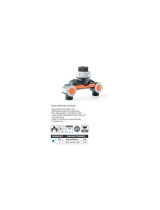
The modulating furnace operation is based off of negative pressure created by the draft inducer. The furnace control board
receives commands from the room thermostat. The furnace control board then controls the RPM of the (3 phase) inducer by
varying the frequency and voltage to the inducer. This is known as variable frequency drive (VFD). The inducer, pressure
switches, and gas valve are linked by pneumatic tubing. The gas valve modulates based on this negative pressure.
5
9
4
3
12
16
28
32
11
14
15
30
17
18
2
19
21
27
24
25
20
23
26
20
22
13
30
29
31
1
6
7
7
8
8
8
Both Sides
10
UPFLOW/HORIZONTAL
Figure 1
T
O
PREVENT
PROPERTY
DAMAGE
,
PERSONAL
INJURY
OR
DEATH
DUE
TO
FIRE
,
DO
NOT
INSTALL
THIS
FURNACE
IN
A
MOBILE
HOME
,
TRAILER
,
OR
RECREATIONAL
VEHICLE
.
WARNING
2
5
6
9
10
11
3
12
13
16
18
19
20
23
25
26
27
21
20
31
32
7
7
88
88
88
4
2
17
15
1
COUNTERFLOW/HORIZONTAL
Figure 2

6
1 Gas Valve 17 Electrical Connection Inlets (Alternate)
2 Gas Line Entrance (Alternate) 18 Coil Front Cover Pressure Tap
3 Pressure Switch(es) 19 Coil Front Cover Drain Port
4 Gas Manifold 20 Drain Line Penetrations
5 Combustion Air Intake Connection 21 Drain Trap
6 Hot Surface Igniter 22 Blower Door Interlock Switch
7 Rollout Limit 23 Inductor (Not All Models)
8 Burners 24 Integrated Control Module
(with fuse and diagnostic LED)
9 Flame Sensor 25 24 Volt Thermostat Connections
10 Flue Pipe Connection 26 Transformer (40 VA)
11 Flue Pipe 27 ECM Variable Speed Circulator Blower
12 Primary Limit 28 Auxiliary Limit
13 Gas Line Entrance 29 Junction Box
14 Flue Pipe Connection (Alternate) NK 30 Electrical Connection Inlets
15 Rubber Elbow 31 Coil Front Cover
16 Variable-Speed Induced Draft Blower 32 "H" Fitting
P
RODUCT
A
PPLICATION
This furnace is primarily designed for residential home-heating applications. It is NOT designed or certified for use in mobile homes,
trailers or recreational vehicles. Neither is it designed or certified for outdoor applications. The furnace must be installed indoors
(i.e., attic space, crawl space, or garage area provided the garage area is enclosed with an operating door).
This furnace can be used in the following non-industrial commercial applications:
Schools, Office buildings, Churches, Retail stores,
Nursing homes, Hotels/motels, Common or office areas
In such applications, the furnace must be installed with the following stipulations:
• It must be installed per the installation instructions provided and per local and national codes.
• It must be installed indoors in a building constructed on site.
• It must be part of a ducted system and not used in a free air delivery application.
• It must not be used as a “make-up” air unit.
This product is dual certified. Dual certification means that the combustion air inlet pipe is OPTIONAL and the furnace can be
vented as a:
Non-direct vent (single pipe) central forced air furnace in which combustion air is taken from the installation area or from air
ducted from the outside or,
Direct vent (dual pipe) central forced air furnace in which all combustion air supplied directly to the furnace burners through
a special air intake system outlined in these instructions.
• All other warranty exclusions and restrictions apply This furnace is an ETL dual-certified appliance and is appropriate for use
with natural or propane gas (NOTE: If using propane, a propane conversion kit is required).
This furnace may be used as a construction site heater ONLY if all of the following conditions are met:
• The vent system is permanently installed per these installation instructions.
• A room thermostat is used to control the furnace. Fixed jumpers that provide continuous heating CANNOT be used and can
cause long term equipment damage.
• Return air ducts are provided and sealed to the furnace.
• A return air temperature range between 60ºF (16ºC) and 80ºF (27ºC) is maintained.
• Air filters are installed in the system and maintained during construction replaced as appropriate during construction, and
upon completion of construction.
• The input rate and temperature rise are set per the furnace rating plate.
• 100% outside air is provided for combustion air requirements during construction. Temporary ducting can be used.
NOTE: Do not connect the temporary duct directly to the furnace. The duct must be sized for adequate combustion and
ventilation in accordance with the latest edition of the National Fuel Gas Code NFPA 54/ANSI Z223.1 or CAN/CSA B149.1
Installation Codes.
• The furnace heat exchanger, components, duct system, air filters and evaporator coils are thoroughly cleaned following final
construction clean up.

7
• All furnace operating conditions (including ignition, input rate, temperature rise and venting) are verified according to these
installation instructions.
NOTE: The Commonwealth of Massachusetts requires that the following additional requirements must also be met:
• Gas furnaces must be installed by a licensed plumber or gas fitter.
• A T-handle gas cock must be used.
• If the unit is to be installed in an attic, the passageway to and the service area around the unit must have flooring.
To ensure proper furnace operation, install, operate and maintain the furnace in accordance with these installation and
operation instructions, all local building codes and ordinances. In their absence, follow the latest edition of the National Fuel Gas
Code (NFPA 54/ANSI Z223.1), and/or CAN/CSA B149.1 Installation Codes, local plumbing or waste water codes, and other applicable
codes.
A copy of the National Fuel Gas Code (NFPA 54/ANSI Z223.1) can be obtained from any of the following:
American National Standards Institute National Fire Protection Association CSA International
25 West 43rd Street, 4th Floor 1 Batterymarch Park 8501 East Pleasant Valley
New York, NY 10036 Quincy, MA 02169-7471 Independence, OH 44131
The rated heating capacity of the furnace should be greater than or equal to the total heat loss of the area to be heated. The total heat
loss should be calculated by an approved method or in accordance with “ASHRAE Guide” or “Manual J-Load Calculations” published by
the Air Conditioning Contractors of America.
A copy of the CAN/CSA B149.1 Installation Codes can also be obtained from:
CSA International
178 Rexdale Boulevard
Etobicoke, Ontario, Canada M9W 1R3
L
OCATION
R
EQUIREMENTS
& C
ONSIDERATIONS
Follow the instructions listed below and the guidelines provided in the Combustion and Ventilation Air Requirements section when
selecting a furnace location.
• Centrally locate the furnace with respect to the proposed or
existing air distribution system.
• Ensure the temperature of the return air entering the furnace
is between 55°F and 100°F when the furnace is heating.
• Provide provisions for venting combustion products outdoors
through a proper venting system. Special consideration should
be given to vent/flue pipe routing and combustion air intake
pipe when applicable. Refer to Vent/Flue Pipe and Combustion
Air Pipe -Termination Locations for appropriate termination
locations and to determine if the piping system from furnace
to termination can be accomplished within the guidelines
given. NOTE: The length of flue and/or combustion air piping
can be a limiting factor in the location of the furnace.
• Locate the furnace so condensate flows downwards to the
drain. Do not locate the furnace or its condensate drainage
system in any area subject to below freezing temperatures without proper freeze protection. Refer to Condensate Drain
Lines and Trap for further details.
• Ensure adequate combustion air is available for the furnace. Improper or insufficient combustion air can expose building
occupants to gas combustion products that could include carbon monoxide. Refer to Combustion and Ventilation Air
Requirements.
• Set the furnace on a level floor to enable proper condensate drainage. If the floor becomes wet or damp at times, place the
furnace above the floor on a concrete base sized approximately 1-1/2" larger than the base of the furnace. Refer to the
Horizontal Applications and Considerations for leveling of horizontal furnaces.
T
O
PREVENT
POSSIBLE
EQUIPMENT
DAMAGE
,
PROPERTY
DAMAGE
,
PERSONAL
INJURY
OR
DEATH
,
THE
FOLLOWING
BULLET
POINTS
MUST
BE
OBSERVED
WHEN
INSTALLING
THIS
UNIT
.
WARNING
P
OSSIBLE
PROPERTY
DAMAGE
,
PERSONAL
INJURY
OR
DEATH
DUE
TO
FIRE
,
EXPLOSION
,
SMOKE
,
SOOT
,
CONDENSATION
,
ELECTRICAL
SHOCK
OR
CARBON
MONOXIDE
MAY
RESULT
FROM
IMPROPER
INSTALLATION
,
REPAIR
OPERATION
,
OR
MAINTENANCE
OF
THIS
PRODUCT
.
WARNING

8
• Ensure upflow or horizontal furnaces are not installed directly on carpeting, or any other combustible material. The only
combustible material allowed is wood.
• A special accessory subbase must be used for upright counterflow unit installations over any combustible material (including
wood). Refer to subbase instructions for installation details. (NOTE: A subbase will not be required if an air conditioning coil
is located beneath the furnace between the supply air opening and the combustible floor.
• Exposure to contaminated combustion air will result in safety and performance-related problems. Do not install the furnace
where the combustion air is exposed to the following substances:
permanent wave solutions chlorinated waxes or cleaners
chlorine-based swimming pool chemicals water softening chemicals
deicing salts or chemicals carbon tetrachloride
halogen type refrigerants cleaning solutions (such as perchloroethylene)
printing inks paint removers
varnishes hydrochloric acid
cements and glues antistatic fabric softeners for clothes dryers
and masonry acid washing materials
• Isolate a non-direct furnace from an area contaminated by any of the above substances. This protects the non-
direct vent furnace from airborne contaminants. To ensure that the enclosed non-direct vent furnace has an adequate
supply of combustion air, air must be ducted in from a nearby uncontaminated room or from outdoors. Refer to the
Combustion and Ventilation Air Requirements for details.
• If the furnace is used in connection with a cooling unit, install the furnace upstream or in parallel with the cooling
coil. Premature heat exchanger failure will result if the cooling coil is placed upstream of the furnace.
For vertical (upflow or downflow) applications, the minimum cooling coil width shall not be less than furnace width
minus 1”. Additionally, a coil installed above an upflow furnace or under a counterflow furnace may be the same
width as the furnace or may be one size larger than the furnace. Example: a “C” width coil may be installed with
a “B” width furnace.
For upflow applications, the front of the coil and furnace must face the same direction.
• If the furnace is installed in a residential garage, position the furnace so that the burners and ignition source are located not
less than 18 inches (457 mm) above the floor. Protect the furnace from physical damage by vehicles.
• If the furnace is installed horizontally, ensure the access doors are not on the “up/top” or “down/bottom” side of the
furnace.
• Do not connect this furnace to a chimney flue that serves a separate appliance designed to burn solid fuel.
• On Counterflow Installations, the air conditioning coil must be downstream on the supply (positive) side of the furnace heat
exchanger.
• Counterflow Installation over a noncombustible floor. Before setting the furnace over the plenum opening, ensure the
surface around the opening is smooth and level. A tight seal should be made between the furnace base and floor by using a
silicone rubber caulking compound or cement grout.
• Counterflow Installation over a combustible floor. If installation over a combustible floor becomes necessary, use an accessory
subbase (see Specification Sheet applicable for your model for details.) A special accessory subbase must be used for upright
counterflow unit installations over any combustible material including wood. Refer to subbase instructions for installation
details. Follow the instructions with the subbase for proper installation. Do not install the furnace directly on carpeting, tile,
or other combustible material other than wood flooring. (NOTE: The subbase will not be required if an air conditioning coil
is installed between the supply air opening on the furnace and the floor.)
CLEARANCES AND ACCESSIBILITY
NOTES:
• For servicing or cleaning, a 24” front clearance is required.
• Unit connections (electrical, flue and drain) may necessitate
greater clearances than the minimum clearances listed above.
• In all cases, accessibility clearance must take precedence over
clearances from the enclosure where accessibility clearances are
greater.
POSITION* FRONT SIDES REAR TOP FLUE FLOOR
Upflow 3" 0" 0" 1" 0" C
Horizontal Alc ove 6" 0" 4" 0" C
C = If placed on combustible floor, floor MUST be wood only.
*MVM97* MINIMUM CLEARANCES TO COMBUSTIBLE MATERIALS
(INCHES)

9
NOTES:
• For servicing or cleaning, a 24” front clearance is required.
• Unit connections (electrical, flue and drain) may necessitate
greater clearances than the minimum clearances listed above.
• In all cases, accessibility clearance must take precedence over
clearances from the enclosure where accessibility clearances are
greater.
Installations must adhere to the clearances to combustible materi-
als to which this furnace has been design certified. The minimum
clearance information for this furnace is provided on the unit’s
clearance label. These clearances must be permanently maintained.
Clearances must also accommodate an installation’s gas, electri-
cal, and drain trap and drain line connections.
NOTE: In addition to the required clearances to combustible mate-
rials, a minimum of 24 inches service clearance must be available
in front of the unit.
EXISTING FURNACE REMOVAL
NOTE: When an existing furnace is removed from a venting system serving other appliances, the venting system may be too large to
properly vent the remaining attached appliances.
The following vent testing procedure is reproduced from the American National Standard/National Standard of Canada for
Gas-Fired Central Furnaces ANSI Z21.4, CSA-2.3 latest edition Section 1.23.1.
The following steps shall be followed with each appliance connected to the venting system placed in operation, while any
other appliances connected to the venting system are not in operation:
1. Seal any unused openings in the venting system;
2. Inspect the venting system for proper size and horizontal pitch, as required by the National Fuel Gas Code, ANSI Z223.1
or the Natural Gas and Propane Installation Code, CSA B149.1-05 and these instructions. Determine that there is no
blockage or restriction, leakage, corrosion and other deficiencies which could cause an unsafe condition.
3. As far as practical, close all building doors and windows and all doors between the space in which the appliance(s)
connected to the venting system are located and other spaces of the building.
4. Close fireplace dampers.
5. Turn on clothes dryers and any appliance not connected to the venting system. Turn on any exhaust fans, such as range
hoods and bathroom exhausts, so they shall operate at maximum speed. Do not operate a summer exhaust fan.
6. Follow the lighting instructions. Place the appliance being inspected in operation. Adjust thermostat so appliance shall
operate continuously.
7. Test for spillage from draft hood appliances at the draft hood relief opening after 5 minutes of main burner operation.
Use the flame of a match or candle.
8. If improper venting is observed during any of the above tests, the venting system must be corrected in accordance with
the National Fuel Gas Code ANSI Z223.1/NFPA 54 and/or National Gas and Propane Installation Code CSA B149.1-05.
9. After it has been determined that each appliance connected to the venting system properly vents when tested as outlined
above, return doors, windows, exhaust fans, fireplace dampers and any other gas burning appliance to their previous
conditions of use.
If resizing is required on any portion of the venting system, use the appropriate table in Appendix G in the latest edition of the
National Fuel Gas Code ANSI Z223.1 and/or CSA B149.1-05 Installation Codes.
POSITION* SIDES REAR FRONT BOTTOM FLUE TOP
Counterflow0"0"3"NC0"1"
Horizontal 6" 0" 3" C 0" 6"
C = If placed on combustible floor, floor MUST be wood only.
NC = For installation on non-combustible floors only. A combustible subbase
must
b
e use
d
f
or
i
nsta
ll
at
i
ons on com
b
ust
ibl
e
fl
oor
i
ng.
*CVM97* MINIMUM CLEARANCES TO COMBUSTIBLE MATERIALS
(INCHES)
TOP
BOTTOM
SIDE SIDE SIDE
TOP
BOTTOM
Upflow Counterflow Horizontal
Figure 3

10
THERMOSTAT LOCATION
The thermostat should be placed approximately five feet from the floor on a vibration-free, inside wall in an area having good air
circulation. Do not install the thermostat where it may be influenced by any of the following:
• Drafts, or dead spots behind doors, in corners, or under cabinets.
• Hot or cold air from registers.
• Radiant heat from the sun.
• Light fixtures or other appliances.
• Radiant heat from a fireplace.
• Concealed hot or cold water pipes, or chimneys.
• Unconditioned areas behind the thermostat, such as an outside wall.
Consult the instructions packaged with the thermostat for mounting instructions and further precautions.
C
OMBUSTION
& V
ENTILATION
A
IR
R
EQUIREMENTS
Improved construction and additional insulation in buildings have
reduced heat loss by reducing air infiltration and escape around
doors and windows. These changes have helped in reducing heat-
ing/cooling costs but have created a problem supplying combus-
tion and ventilation air for gas fired and other fuel burning appli-
ances. Appliances that pull air out of the house (clothes dryers,
exhaust fans, fireplaces, etc.) increase the problem by starving
appliances of air.
House depressurization can cause back drafting or improper combustion of gas-fired appliances, thereby exposing building occu-
pants to gas combustion products that could include carbon monoxide.
When the furnace is installed as a direct vent (2-pipe system) furnace, no special provisions for air for combustion are
required. However, if this furnace is to be installed in the same space with other gas appliances, such as a water heater, ensure
there is an adequate supply of combustion and ventilation air for the other appliances. Refer to the latest edition of the National
Fuel Gas Code NFPA 54/ANSI Z223.1 or CAN/CSA B149 Installation Codes or applicable provisions of the local building codes for
determining the combustion air requirements for the appliances.
Most homes will require outside air be supplied to the furnace area by means of ventilation grilles or ducts connecting directly to
the outdoors or spaces open to the outdoors such as attics or crawl spaces.
The following information on air for combustion and ventilation is reproduced from the National Fuel Gas Code NFPA 54/ANSI Z223.1
Section 9.3.
9.3* Air for Combustion and Ventilation.
9.3.1 General.
9.3.1.1 Air for combustion, ventilation, and dilution of flue gases for appliances installed in buildings shall be obtained by application of one of the
methods covered in 9.3.2 through 9.3.6. Where the requirements of 9.3.2 are not met, outdoor air shall be introduced in accordance with methods covered
in 9.3.3 through 9.3.6.
Exception No. 1: This provision shall not apply to direct vent appliances.
9.3.1.2 Appliances of other than natural draft design and other than Category 1 vented appliances shall be provided with combustion, ventilation, and
dilution air in accordance with the appliance manufacturer’s instructions.
9.3.1.3 Appliances shall be located so as not to interfere with proper circulation of combustion, ventilation, and dilution air.
9.3.1.4 Where used, a draft hood or a barometric draft regulator shall be installed in the same room or enclosure as the appliance served so as to prevent
any difference in pressure between the hood or regulator and the combustion air supply.
9.3.1.5 Makeup air requirements for the operation of exhaust fans, kitchen ventilation systems, clothes dryers, and fireplaces shall be considered in
determining the adequacy of a space to provide combustion air requirements.
T
O
AVOID
PROPERTY
DAMAGE
,
PERSONAL
INJURY
OR
DEATH
,
SUFFICIENT
FRESH
AIR
FOR
PROPER
COMBUSTION
AND
VENTILATION
OF
FLUE
GASES
MUST
BE
SUPPLIED
. M
OST
HOMES
REQUIRE
OUTSIDE
AIR
BE
SUPPLIED
INTO
THE
FURNACE
AREA
.
WARNING

11
9.3.2 Indoor Combustion Air. The required volume of indoor air shall be determined in accordance with the method in 9.3.2.1 or 9.3.2.2 except that
where the air infiltration rate is known to be less than 0.40 ACH, the method in 9.3.2.2 shall be used. The total required volume shall be the sum of the
required volume calculated for all appliances located within the space. Rooms communicating directly with the space in which the appliances are installed
through openings not furnished with doors, and through combustion air openings sized and located in accordance with 9.3.2.3, are considered a part of the
required volume.
9.3.2.1* Standard Method. The minimum required volume shall be 50 ft
3
per 1,000/Btu/hour (4.8m
3
/kW).
9.3.2.2* Known Air Infiltration Rate Method. Where the air infiltration rate of a structure is known, the minimum required volume shall be determined
as follows:
(1) For appliances other than fan-assisted, calculate using the following equation:
21 ft
3
I
other
Required Volume
other
> ________ _________
ACH 1000 Btu/hr
(2) For fan-assisted appliances, calculate using the following equation:
15 ft
3
I
fan
Required Volume
fan
> ________ _________
ACH 1000 Btu/hr
where:
I
other
= all appliances other than fan-assisted input in Btu per hour
I
fan
= fan-assisted appliances input in Btu per hour
ACH = air change per hour (percent of volume of space exchanged per hour, expressed as a decimal)
(3) For purposes of this calculation, an infiltration rate greater than 0.60 ACH shall not be used in the equations in 9.3.2.2(1) and 9.3.2.2(2).
9.3.2.3 Indoor Opening Size and Location. Openings used to connect indoor spaces shall be sized and located in accordance with the following:
(1)*Combining spaces on the same story. Each opening shall have a minimum
free area of 1 in.
2
/1000Btu/hr (2200 mm
2
/kW) of the total input rating of
all appliances in the space but not less than 100 in.
2
(0.60m
2
). One
opening shall commence within 12 in. (300 mm) of the top, and one
opening shall commence within 12 in. (300 mm) of the bottom, of the
enclosure [see Figure A.9.3.2.3(1)]. The minimum dimension of air open-
ings shall be not less than 3 in. (80 mm).
(2) Combining spaces in different stories. The volumes of spaces in different
stories shall be considered as communicating spaces where such spaces
are connected by one or more openings in doors or floors having a total
minimum free area of 2 in.
2
/1000 Btu/hr (4400 mm
2
/kW) of total input
rating of all appliances.
9.3.3 Outdoor Combustion Air. Outdoor combustion air shall be provided
through opening(s) to the outdoors in accordance with the methods in 9.3.3.1
or 9.3.3.2. The minimum dimension of air openings shall not be less than 3 in.
(80 mm).
9.3.3.1 Two Permanent Openings Method. Two permanent openings, one commencing within 12 in. (300 mm) of the top and one commencing within
12 in. (300 mm) of the bottom, of the enclosure shall be provided. The openings shall communicate directly, or by ducts, with the outdoors or spaces that
freely communicate with the outdoors, as follows:
Figure A.9.2.3.3.(1) All Combustion Air from Adjacent
Indoor Spaces through Indoor Combustion Air Openings.
)
(
)(

12
(1)*Where directly communicating with the outdoors or where communicating to the outdoors through vertical ducts, each opening shall have a minimum
free area of 1 in.
2
/4000 Btu/hr (550 min
2
/kW) of total input rating of all appliances in the enclosure. [See Figure A.9.3.3.1(1)(a) and Figure
A.9.3.3.1(1)(b).]
(2)*Where communicating with the outdoors through horizontal ducts, each
opening shall have a minimum free area of 1 in.
2
/2000 Btu/hr (1100 min
2
/
kW) of total input rating of all appliances in the enclosure. [See Figure
A.9.3.3.1(2).]
9.3.3.2* One Permanent Opening Method. One permanent openings, com-
mencing within 12 in. (300 mm) of the top of the enclosure, shall be provided. The
appliance shall have clearances of at least 1 in. (25 mm) from the sides and back
and 6 in. (150 mm) from the front of the appliance. The opening shall directly
communicate with the outdoors or shall communicate through a vertical or hori-
zontal duct to the outdoors or spaces that freely communicate with the outdoors
(see Figure A.9.3.3.2) and shall have a minimum free area of the following:
(1) 1 in.
2
/3000 Btu/hr (700 mm
2
per kW) of the total input rating of all appliances
located in the enclosure, and
(2) Not less than the sum of the areas of all vent connectors in the space.
Figure A.9.3.3.1(1)(b) All Combustion Air
From Outdoors through Ventilated Attic.
Figure A.9.3.3.1(1)(a) All Combustion Air From Outdoors -
Inlet Air from Ventilated Crawl Space and Outlet Air to Ventilated Attic.
Figure A.9.3.3.1(2) All Combustion Air From Outdoors
through Horizontal Ducts.
Figure A.9.3.3.2 All Combustion Air
From Outdoors through Single Combustion Air Opening.

13
9.3.4 Combination Indoor and Outdoor Combustion Air. The use of a combination of indoor and outdoor combustion air shall be in accordance with
(1) through (3) (see example calculation in Annex J]:
(1) Indoor Openings: Where used, openings connecting the interior spaces shall comply with 9.3.2.3.
(2) Outdoor Opening(s) Location. Outdoor opening(s) shall be located in accordance with 9.3.3.
(3) Outdoor Opening(s) Size. The outdoor opening(s) size shall be calculated in accordance with the following:
(a) The ratio of the interior spaces shall be the available volume of all communicating spaces divided by the required volume.
(b) The outdoor size reduction factor shall be 1 minus the ratio of interior spaces.
(c) The minimum size of outdoor opening(s) shall be the full size of outdoor opening(s) calculated in accordance with 9.3.3, multiplied by the
reduction factor. The minimum dimension of air openings shall not be less than 3 in. (80 mm).
9.3.5 Engineered Installations. Engineered combustion air installations shall provide an adequate supply of combustion, ventilation, and dilution air and
shall be approved by the authority having jurisdiction.
9.3.6 Mechanical Combustion Air Supply. Where all combustion air is provided by a mechanical air supply system, the combustion air shall be
supplied form outdoors at the minimum rate of 0.35 ft
3
/min per 1000 Btu/hr (0.034 m
3
/min per kW) for all appliances located within the space.
9.3.6.1 Where exhaust fans are installed, additional air shall be provided to replace the exhausted air.
9.3.6.2 Each of the appliances served shall be interlocked to the mechanical air supply system to prevent main burner operation where the mechanical air
supply system is not in operation.
9.3.6.3 Where combustion air is provided by the building’s mechanical ventilation system, the system shall provide the specified combustion air rate in
addition to the required ventilation air.
9.3.7 Louvers, Grilles, and Screens.
9.3.7.1 Louvers and Grilles. The required size of openings for combustion, ventilation, and dilution air shall be based on the net free area of each opening.
Where the free area through a design of louver or grille or screen is known, it shall be used in calculating the size opening required to provide the free area
specified. Where the louver and grille design and free area are not known, it shall be assumed that wood louvers will have 25 percent free area, and metal
louvers and grilles will have 75 percent free area. Nonmotorized louvers and grilles shall be fixed in the open position.
9.3.7.2 Minimum Scree Mesh Size. Screens shall not be smaller than 1/4 in. mesh.
9.3.7.3 Motorized Louvers. Motorized louvers shall be interlocked with the appliance so they are proven in the full open position prior to main burner
ignition and during main burner operation. Means shall be provided to prevent the main burner form igniting should the louver fail to open during burner
startup and to shut down the main burner if the louvers close during burner operation.
9.3.8 Combustion Air Ducts. Combustion air ducts shall comply with 9.3.8.1 through 9.3.8.8.
9.3.8.1 Ducts shall be constructed of galvanized steel or a material having equivalent corrosion resistance, strength, and rigidity.
Exception: Within dwellings units, unobstructed stud and joist spaces shall not be prohibited from conveying combustion air, provided that not more than
one fireblock is removed.
9.3.8.2 Ducts shall terminate in an unobstructed space, allowing free movement of combustion air to the appliances.
9.3.8.3 Ducts shall serve a single space.
9.3.8.4 Ducts shall not serve both upper and lower combustion air openings where both such openings are used. The separation between ducts servicing
upper and lower combustion air openings shall be maintained to the source of combustion air.
9.3.8.5 Ducts shall not be screened where terminating in an attic space.
9.3.8.6 Horizontal upper combustion air ducts shall not slope downward toward the source of combustion air.
9.3.8.7 The remaining space surrounding a chimney liner, gas vent, special gas vent, or plastic piping installed within a masonry, metal, or factory built
chimney shall not be used to supply combustion air.
Exception: Direct vent appliances designed for installation in a solid fuel-burning fireplace where installed in accordance with the manufacture’s
installation instructions.
9.3.8.8 Combustion air intake openings located on the exterior of the building shall have the lowest side of the combustion air intake openings located at
least 12 in. (300 mm) vertically from the adjoining grade level.

14
I
NSTALLATION
P
OSITIONS
A/GMVM97 models may be installed upflow or horizontally with left or right side down. A/GCVM97 models may be installed
downflow or horizontally with left or right side down.
Do not install this furnace on its back. For upright upflow furnaces, return air ductwork may be attached to the side panel(s) and/
or basepan. For horizontal upflow furnaces, return air ductwork must be attached to the basepan. For both upright or horizontal
counterflow furnaces, return ductwork must be attached to the basepan (top end of the blower compartment). NOTE:
Ductwork
must never be attached to the back of the furnace. Refer to “Recommended Installation Positions” figure for appropriate
installation positions, ductwork connections, and resulting airflow arrangements.
H
ORIZONTAL
A
PPLICATIONS
& C
ONSIDERATIONS
When installing a furnace horizontally, additional con-
sideration must be given to the following:
FURNACE SUSPENSION
If suspending the furnace from rafters or joists, use
3/8" threaded rod and 2”x2”x1/8” angle iron as shown
in the following diagram. The length of rod will depend
on the application and the clearances necessary.
If the furnace is installed in a crawl space it must be
suspended from the floor joist or supported by a con-
crete pad. Never install the furnace on the ground or
allow it to be exposed to water.
Figure 4A
Figure 4B
Figure 4C
Recommended Installation Positions
2" 2" 3/8"
ANGLE
IRON
(3
PLACES
)
XX
Figure 5

15
FRONT COVER PRESSURE SWITCH TUBE LOCATION
When an upflow model is installed horizontally with left side down or a counterflow model is installed horizontally with right
side down, the front cover pressure switch tube must be re-located to the lower port of the collector box cover.
1. Remove tube from front cover pressure switch and collector box cover.
2. Remove rubber plug from bottom collector box port and install on top collector box port.
3. Locate 24” x 1/4” tube in parts bag.
4. Install one end on front cover pressure switch.
5. Route tube to lower port on collector box cover and cut off excess tubing.
DRAIN TRAP AND LINES
In horizontal applications the condensate drain trap is secured to the furnace side panel, suspending it below the furnace. A minimum
clearance of 5 1/2 inches below the furnace must be provided for the drain trap. Additionally, the appropriate downward piping slope
must be maintained from the drain trap to the drain location. Refer to Condensate Drain Trap and Lines for further details. If the drain
trap and drain line will be exposed to temperatures near or below freezing, adequate measures must be taken to prevent condensate
from freezing.
LEVELING
Leveling ensures proper condensate drainage from the heat exchanger and induced draft blower. For proper flue pipe drainage, the
furnace must be level lengthwise from end to end. The furnace should have a slight tilt from back to front with the access doors
downhill from the back panel approximately 1/2 to 3/4 inches. The slight tilt allows the heat exchanger condensate, generated in
the recuperator coil, to flow forward to the recuperator coil front cover.
ALTERNATE ELECTRICAL AND GAS LINE CONNECTIONS
This furnace has provisions allowing for electrical and gas line connections through either side panel. In horizontal applications the
connections can be made either through the “top” or “bottom” of the furnace.
DRAIN PAN
A drain pan must be provided if the furnace is installed above a conditioned area. The drain pan must cover the entire area under the
furnace (and air conditioning coil if applicable).
FREEZE PROTECTION
Refer to Horizontal Applications and Conditions - Drain Trap and Lines.
P
ROPANE
G
AS
/H
IGH
A
LTITUDE
I
NSTALLATIONS
This furnace is shipped from the factory configured for natural gas
up to 10,000 ft. altitude. Propane conversions require the proper
LP kit to compensate for the energy content difference between
natural and propane gas.
For furnaces being converted to LP gas, it is strongly recom-
mended that a LPLP03 kit also be installed. The use of this kit
will prevent the furnace from firing when the LP gas supply
pressure is too low to support proper combustion.
The indicated kit must be used to ensure safe and proper furnace
operation. All conversions must be performed by a qualified in-
staller, or service agency.
WARNING
P
OSSIBLE
PROPERTY
DAMAGE
,
PERSONAL
INJURY
OR
DEATH
MAY
OCCUR
IF
THE
CORRECT
CONVERSION
KITS
ARE
NOT
INSTALLED
. T
HE
APPROPRIATE
KITS
MUST
BE
APPLIED
TO
ENSURE
SAFE
AND
PROPER
FURNACE
OPERATION
. A
LL
CONVERSIONS
MUST
BE
PERFORMED
BY
A
QUALIFIED
INSTALLER
OR
SERVICE
AGENCY
.
High
Stage
Low Stage
(50% firing
rate)
Natural None #45
1
3.5" w.c. 1" w.c. None
Propane LPM-09 1.25MM
2
10.0" w.c. 2.6" w.c. None
OrificeGas
0-10,000
Manifold Pressure
Pressure
Switch
Change
Altitude Kit
NOTE:
In Canada, gas furnaces are only certified to 4500 feet.

16
V
ENT
/F
LUE
P
IPE
& C
OMBUSTION
A
IR
P
IPE
A condensing gas furnace achieves its high level of efficiency by
extracting almost all of the heat from the products of combustion
and cooling them to the point where condensation takes place. Be-
cause of the relatively low flue gas temperature and water conden-
sation requirements, PVC or ABS pipe is used as venting material.
In addition to PVC and ABS pipe and fittings, Innoflue
®
by
Centrotherm Eco Systems and PolyPro
®
by M&G Duravent are
also approved vent and combustion air materials for installa-
tions in the U.S.A. and Canada. Manufacturers Installation in-
structions for these products must be followed. These products
have specific instructions for installing, joining and terminat-
ing. Do not mix materials or components of one manufacturer
with materials or components of another manufacturer.
All furnaces are built with 2" vent / intake pipe and connectors. For furnaces requiring installation of 3" pipe, the transition
from 2" to 3" should be done as close to the furnace as practically possible.
This furnace must not be connected to Type B, BW, or L vent or vent connector, and must not be vented into any portion of a factory
built or masonry chimney except when used as a pathway for PVC as described later in this section. Never common vent this appliance
with another appliance or use a vent which is used by a solid fuel appliance.
It is the responsibility of the installer to follow the manufacturers’ recommendations and to verify that all vent/flue piping and
connectors are compatible with furnace flue products. Additionally, it is the responsibility of the installer to ensure that all piping and
connections possess adequate structural integrity and support to prevent flue pipe separation, shifting, or sagging during furnace
operation.
DUAL CERTIFICATION: NON-DIRECT/DIRECT VENT
This furnace is dual certified and may be installed as a non-direct
vent (single pipe) or direct vent (dual pipe) appliance. A non-direct
vent installation requires only a vent/flue pipe, while a direct vent
installation requires both a vent/flue pipe and a combustion air
intake pipe. Refer to the appropriate section for details concerning
piping size, length, number of elbows, furnace connections, and
terminations.
MATERIALS AND JOINING METHODS
Two- or three-inch nominal diameter PVC Schedule 40 pipe meeting ASTM D1785, PVC primer meeting ASTM F656, and PVC solvent
cement meeting ASTM D2564 specifications must be used. Fittings must be DWV type fittings meeting ASTM D2665 and ASTM D3311.
Carefully follow the pipe manufacturer’s instructions for cutting, cleaning, and solvent cementing of PVC.
The use of Schedule 40 PVC or ABS cellular core (Foam Core) plastic pipe is also acceptable as a flue/vent and intake pipe material.
PVC primer meeting ASTM F656 and PVC solvent cement meeting ASTM D2564 specifications must be used. Fittings must be DWV
type fittings meeting ASTM D2665 and ASTM D3311. Carefully follow the manufactures instructions for cutting, cleaning and solvent
cementing of PVC.
For Canadian installations; all PVC pipe, fittings and joining materials must be UL S636 listed.
As an alternative to PVC pipe, primer, solvent cement, and fittings, ABS materials which are in compliance with the
following specifications may be used: Two-or-three-inch solid wall ABS Schedule 40 pipe must meet ASTM D1527 and, if used
in Canada, must be CSA listed or, two-or-three-inch cellular core ABS Schedule 40 pipe must meet ASTM F628 and, if used in
Canada, must be CSA listed. Solvent cement for ABS to ABS joints must meet ASTM D2235 and, if used in Canada, must be
CSA listed. The solvent cement for the PVC to ABS transition joint must meet ASTM D3138. Fittings must be DWV type
fittings meeting ASTM D2661 and ASTM D3311 and, if used in Canada, must be CSA listed. Carefully follow the manufactur-
ers’ instructions for cutting, cleaning, and solvent cementing PVC and/or ABS.
All 90° elbows must be medium radius (1/4 bend DWV) or long radius (Long sweep 1/4 bend DWV) types conforming to ASTM D3311.
A medium radius (1/4 bend DWV) elbow measures 3 1/16” minimum from the plane of one opening to the centerline of the other
opening for 2” diameter pipe, and 4 9/16” minimum for 3” pipe.
The use of two short radius 45 degree elbows is permitted to provide clearance to refrigerant piping above the furnace.
F
AILURE
TO
FOLLOW
THESE
INSTRUCTIONS
CAN
RESULT
IN
BODILY
INJURY
OR
DEATH
. C
AREFULLY
READ
AND
FOLLOW
ALL
INSTRUCTIONS
GIVEN
IN
THIS
SECTION
.
WARNING
U
PON
COMPLETION
OF
THE
FURNACE
INSTALLATION
,
CAREFULLY
INSPECT
THE
ENTIRE
FLUE
SYSTEM
BOTH
INSIDE
AND
OUTSIDE
OF
THE
FURNACE
TO
ASSURE
IT
IS
PROPERLY
SEALED
. L
EAKS
IN
THE
FLUE
SYSTEM
CAN
RESULT
IN
SERIOUS
PERSONAL
INJURY
OR
DEATH
DUE
TO
EXPOSURE
TO
FLUE
PRODUCTS
,
INCLUDING
CARBON
MONOXIDE
.
WARNING
T
O
AVOID
BODILY
INJURY
,
FIRE
OR
EXPLOSION
,
SOLVENT
CEMENTS
MUST
BE
KEPT
AWAY
FROM
ALL
IGNITION
SOURCES
(
I
.
E
.,
SPARKS
,
OPEN
FLAMES
,
AND
EXCESSIVE
HEAT
)
AS
THEY
ARE
COMBUSTIBLE
LIQUIDS
.
A
VOID
BREATHING
CEMENT
VAPORS
OR
CONTACT
WITH
SKIN
AND
/
OR
EYES
.
WARNING

17
PROPER VENT/FLUE AND COMBUSTION AIR PIPING PRACTICES
Adhere to these instructions to ensure safe and proper furnace performance. The length,
diameter, and number of elbows of the vent/flue pipe and combustion air pipe (when
applicable) affects the performance of the furnace and must be carefully sized. All
piping must be installed in accordance with local codes and these instructions.
Piping must be adequately secured and supported to prohibit sagging, joint separation,
and/or detachment from the furnace. Horizontal runs of vent/flue and combustion air
piping must be properly supported. PVC pipe supports must be no more than 5'
apart. For ABS pipe, supports must be no more than 3' apart. Horizontal pipe runs
must maintain a 1/4 inch per foot downward slope, back towards the furnace, to
properly return condensate to the furnace’s drain system.
Precautions should be taken to prevent condensate from freezing inside the vent/flue
pipe and/or at the vent/flue pipe termination. All vent/flue piping exposed to tem-
peratures below 35°F for extended periods of time must be insulated with 1/2” thick
closed cell foam. Also, all vent/flue piping exposed outdoors in excess of the termina-
tions shown in this manual (or in unheated areas) must be insulated with 1/2” thick
closed cell foam. Inspect piping for leaks prior to installing insulation.
TERMINATION LOCATIONS
NOTE: Refer to Location Requirements and Considerations for combustion air
contaminant restrictions.
The following bullets and diagram describe the restrictions concerning the appropriate
location of vent/flue pipe and combustion air intake pipe (when applicable) termina-
tions. Refer to Non-Direct Vent (Single Pipe) Piping and Direct Vent (Dual Pipe) Piping
located in this section for specific details on termination construction.
• All terminations (flue and/or intake) must be located at least 12 inches above
ground level or the anticipated snow level.
• Vent terminations (non-direct and direct vent) must terminate at
least 3 feet above any forced air inlet located within 10 feet.
NOTE: This provision does not apply to the combustion air intake
termination of a direct vent application.
• The vent termination of a direct vent application must terminate
at least 12 inches from any opening through which flue gases may
enter a building (door, window, or gravity air inlet).
• The vent termination running vertically through a roof must
terminate at least 12 inches above the roof line (or the anticipated
snow level) and be at least 12 inches from any vertical wall
(including any anticipated snow build up).
• A vent termination shall not terminate over public walkways or
over an area where condensate or vapor could create a nuisance
or hazard or could be detrimental to the operation of regulators,
relief valves, or other equipment.
• The combustion air intake termination of a direct vent application should not terminate in an area which is frequently dusty
or dirty.
NOTE: In Canada, the current edition of CAN/CSA B149.1 takes precedence over the preceding termination restriction.
PREFERRED
Figure 6
TRANSITION NO LESS
THAN 45 DEGREES TO
HORIZONTAL PLANE TO
AVOID CREATING A WATER
TRAP IN VENT PIPING.
ACCEPTABLE
Figure 7
NO TRANSITION ON
HORIZONTAL PLANE,
THIS CREATES A
WATER TRAP AND
RESTRICTS FLUE
GASES
Figure 8

18
DIRECT VENT TERMINAL CLEARANCES
OTHER THAN DIRECT VENT TERMINAL CLEARANCES
v
V
X
1 In accordance with the current CSA B149.1, Natural Gas and Propane Installation Code.
2 In accordance with the current ANSI Z223.1/NFPA 54, National Fuel Gas Code.
† A vent shall not terminate directly above a sidewalk or paved driveway that is located between two single family dwellings and serves
both dwellings.
‡ Permitted only if veranda, porch, deck or balcony is fully open on a minimum of two sides beneath the floor.
* For clearances not specified in ANSI Z223.1/NFPA 54 or CSA B149.1, the following statement shall be included:
“Clearance in accordance with local installation codes and the requirements of the gas supplier and the manufacturer’s installation instruction.”
1 In accordance with the current CSA B149.1, Natural Gas and Propane Installation Code.
2 In accordance with the current ANSI Z223.1/NFPA 54, National Fuel Gas Code.
† A vent shall not terminate directly above a sidewalk or paveable driveway that is located between two single family dwellings and serves
both dwelling.
‡ Permitted only if veranda, porch, deck or balcony is fully open on a minimum of two sides beneath the floor.
* For clearances not specified in ANSI Z223.1/NFPA 54 or CSA B149.1, the following statement shall be included:
“Clearance in accordance with local installation codes and the requirements of the gas supplier and the manufacturer’s installation instruction.”
Canadian Installations
1
U.S. Installations
2
I= Clearance to sevice
regulator vent outlet.
3 ft. (91 cm). *
J= Clearance to nonmechanical air
supply inlet to building or the
combustion air inlet to any other
appliance.
6 in. (15 cm) for appliances 10,000
Btuh (3 kW), 12 in. (30 cm) for
appliances > 10,000 Btuh (3kW) and
100,000 Btuh (30 kW), 36 in. (91 cm)
for appliances > 100,000 Btuh (30 kW).
4 ft. (1.2 m) below or to side of
opening; 1 ft. (300 m) above opening.
K= Clearance to a mechanical
air supply inlet.
6 ft. (1.83 m) 3 ft. (91 cm) above if within
10 ft. (3 m) horizontally.
L= Clearance above paved sidewalk or
paved driveway located on public
property.
7 ft. (2.13m) † 7 ft. (2.13m)
M= Clearance under veranda, porch,
deck or balcony.
12 in. (30 cm) ‡ *
Canadian Installations
1
U.S. Installations
2
I= Clearance to service
regulator vent outlet.
3 ft. (91 cm). *
J= Clearance to nonmechanical air
supply inlet to building or the
combustion air inlet to any other
appliance.
6 in. (15 cm) for appliances 10,000
Btuh (3 kW), 12 in. (30 cm) for
appliances > 10,000 Btuh (3kW) and
100,000 Btuh (30 kW), 36 in. (91 cm)
for appliances > 100,000 Btuh (30 kW).
6 in. (15 cm) for appliances 10,000
Btuh (3 kW), 9 in. (23 cm) for
appliances > 10,000 Btuh (3kW) and
50,000 Btuh (15 kW), 12 in. (30 cm) for
appliances > 50,000 Btuh (15 kW).
K= Clearance to a mechanical
air supply inlet.
6 ft. (1.83 m) 3 ft. (91 cm) above if within
10 ft. (3 m) horizontally.
L= Clearance above paved sidewalk or
paved driveway located on public
property.
7 ft. (2.13m) † *
M= Clearance under veranda, porch,
deck or balcony.
12 in. (30 cm) ‡ *
Canadian Installations
1
U.S. Installations
2
A= Clearance above grade,
veranda, porch, deck or
balcony. (See 1.24.6-i(9)b.)
12 in. (30 cm) 12 in. (30 cm)
B= Clearance to window or
door that may be opened.
6 in. (15 cm) for appliances
10,000 Btuh (3 kW), 12 in. (30 cm) for
appliances > 10,000 Btuh (3 kW) and
100,000 Btuh (30 kW), 36 in. (91 cm)
for appliances > 100,000 Btuh (30
kW).
4 ft. (1.2 m) below or to side of
opening; 1 ft. (300 m) above opening.
C= Clearance to permanently
closed window.
**
D= Vertical clearance to ventilated soffit
located above the terminal within a
horizontal distance of 2 feet (61 cm)
from the center line of the terminal.
**
E= Clearance to unventilated soffit. * *
F= Clearance to outside corner. * *
G= Clearance to inside corner. * *
H= Clearance to each side of center
line extended above meter/regulator
assembly.
3 ft. (91 cm) within a height 15 ft.
(4.5 m) above the meter/regulator
assembly.
*
Canadian Installations
1
U.S. Installations
2
A= Clearance above grade,
veranda, porch, deck or
balcony. (See 1.24.6-i(9)b.)
12 in. (30 cm) 12 in. (30 cm)
B= Clearance to window or
door that may be opened.
6 in. (15 cm) for appliances
10,000 Btuh (3 kW), 12 in. (30 cm) for
appliances > 10,000 Btuh (3 kW) and
100,000 Btuh (30 kW), 36 in. (91 cm)
for appliances > 100,000 Btuh (30
kW).
6 in. (15 cm) for appliances
10,000 Btuh (3 kW), 9 in. (23 cm) for
appliances > 10,000 Btuh (3 kW) and
50,000 Btuh (15 kW), 12 in. (30 cm) for
appliances > 500,000 Btuh (15 kW).
C= Clearance to permanently
closed window.
**
D= Vertical clearance to ventilated soffit
located above the terminal within a
horizontal distance of 2 feet (61 cm)
from the center line of the terminal.
**
E= Clearance to unventilated soffit. * *
F= Clearance to outside corner. * *
G= Clearance to inside corner. * *
H= Clearance to each side of center
line extended above meter/regulator
assembly.
3 ft. (91 cm) within a height 15 ft.
(4.5 m) above the meter/regulator
assembly.
*

19
SPECIAL VENTING REQUIREMENTS FOR INSTALLATIONS IN CANADA
All installations in Canada must conform to the requirements of CAN/CSA B149.1 code. All vent system components, including
primer and cement, must be listed to ULC S636. The certified pipe and fittings should be clearly marked with the ULC
standard “S636”. The primer and cement used must be of the same manufacturer as the vent system. For Royal Pipe System
636; use GVS-65 Primer (Purple) and GVS-65 PVC Solvent Cement. For IPEX System 636, use PVC/CPVC Primer, Purple or
clear. Use PVC Solvent Cement (Gray).
For Canadian installations, ABS may be used as a combustion air pipe only. ABS is not an approved vent material in Canada.
If ABS is used as a combustion air pipe, it must be CSA certified. Always follow the manufacturer’s instructions in the use of
primer and cement. Do not use primer and cement around potential sources of ignition. Do not use primer or cement beyond
its expiration date.
The safe operation, as defined by ULC S636, of the vent system is based on following these installation instructions, the vent
system manufacturer’s installation instructions, and proper use of primer and cement. It is recommended under this stan-
dard, that the vent system be checked once a year by qualified service personnel. All fire stops and roof flashings used with
this system must be UL listed. Acceptability under CAN/CSA B149.1 is dependent upon full compliance with all installation
instructions. Consult the authority having jurisdiction (gas inspection authority, municipal building department, fire depart-
ment, etc.) before installation to determine the need to obtain a permit. *IPEX System 636™ is a trademark of IPEX Inc.
Carefully follow the pipe manufacturers’ instructions for cutting, cleaning, and solvent cementing PVC and/or ABS.
The vent can be run through an existing unused chimney provided the space between the vent pipe and the chimney is insulated and
closed with a weather-tight, corrosion-resistant flashing.
STANDARD FURNACE CONNECTIONS
It is the responsibility of the installer to ensure that the piping connections to the furnace are secure,
airtight, and adequately supported.
VENT PIPE CONNECTION
The vent pipe outlet is sized to accept 2” pipe. Secure vent/flue pipe directly into the furnace
fitting with the appropriate glue. Alternately, a small section of 2" pipe may be glued in the
furnace socket and a rubber coupling installed to allow removal for future service. Combustion
Air and Vent piping should be routed in a manner to avoid contact with refrigerant lines, metering
devices, condensate drain lines, etc. If necessary, clearances may be increased by creating an
offset using two 45 degree elbows. This joint can be rotated on the fitting to establish maximum
clearance between refrigerant lines, metering devices, and condensate drain lines, etc. This joint is
the equivalent of one 90 deg. elbow when considering elbow count.
COMBUSTION AIR PIPE
DIRECT VENT INSTALLATIONS
On upflow units secure the combustion air intake pipe to the air intake coupling by using a
take apart rubber coupling supplied with the furnace or a plastic coupling. Also, the
intake coupling may be inverted to allow the intake pipe to be glued directly to it. After
inverting the coupling, secure it to the furnace top with screws. On counterflow units
secure the combustion air intake pipe to the air intake coupling using the rubber coupling and
worm gear hose clamps provided with the unit. The counterflow rubber coupling allows service
removal of air intake piping internal to the furnace blower compartment. The combustion air
intake pipe can also be secured directly to the counterflow unit air intake pipe coupling.
COMBUSTION AIR INTAKE OPTION: The RF000142 coupling can be secured directly to the
furnace intake coupling if condensation is a concern. If the RF000142 is used on the
combustion air inlet, it must be installed with the arrow pointing up. It should be noted,
the combustion air will actually be moving in a direction opposite of the arrow on the RF000142 coupling. It must have a field
supplied, trapped drain tube free-draining to proper condensate disposal location. A loop in the drain tube can serve as a
trap. The unused RF000142 drain fitting should be capped.
NON-DIRECT V ENT INSTALLATIONS
A minimum of one 90° elbow should be installed on the combustion
air intake “coupling” to guard against inadvertent blockage.
E
DGES
OF
SHEET
METAL
HOLES
MAY
BE
SHARP
. U
SE
GLOVES
AS
A
PRECAUTION
WHEN
REMOVING
HOLE
PLUGS
.
WARNING
45 DEGREE
ELBOWS
Increased Clearance
Figure 9A
Figure 9B
VENT-DRAIN

20
ALTERNATE VENT/FLUE LOCATION
The alternate vent/flue location is the large hole directly in line with
the induced draft blower outlet. To use the alternate vent/flue loca-
tion on an upflow / horizontal model, refer to the following steps
and the “Alternate Vent/Flue Location” figure. To use an alternate
vent location on a counterflow / horizontal model, a special kit
is required.
NOTE: In the horizontal left installation position, a means of
condensate collection must be provided to keep vent pipe
condensate from entering the draft inducer housing. If the vent-
drain elbow is eliminated from the installation; an RF000142 kit
must be used.
1. Remove screws from vent flange.
2. Remove internal elbow and vent pipe.
3. Cut pipe 2 1/2” from flange.
4. Remove cabinet plug adjacent to inducer outlet and install
an original cabinet vent hole.
5. Install RF000142 coupling on inducer outlet.
6. Install flanged vent section removed in step 2 & secure with clamps.
7. Secure flange to cabinet using screws removed in step 1.
ALTERNATE COMBUSTION AIR PROVISION
(Upflow / Horizontal models only)
When using the alternate venting location, either in a horizontal left side down
installation or a vertical installation using down – venting, an alternate combustion
Insert flange. Cut 2 ½” long.
R 000142F
Figure 10
C
U
T
H
E
R
E
Vent/Flue Pipe Cuts
Figure 11
Figure 12
F
l
o
o
r
Use alternate vent
& combination air locations
DOWN VENTING UPFLOW MODEL FURNACES ONLY
B
a
s
e
m
e
n
t
/
C
r
a
w
l
s
p
a
c
e
Condensate trapped
to prevent flue gas from escaping
and routed to field supplied
condensate disposal
Combustion Air Pipe
Vent Pipe
All piping and fittings must be joined per material manufacturer’s specifications
to prevent separation and flue gas leaks.
Both Pipes Terminated
Outside Structure
1/4” per foot min. slope
6’ MAX.
Field Supplied
Drain Tee on Vent Pipe
/