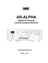
AOR AR5700D Owner's manual

Type
Owner's manual
1
INTRODUCTION
Thank you for purchasing the AR5700D.
AR5700D is a high-end table-top receiver with wide band coverage between 9kHz and 3.7GHz. It supports a variety
of digital, as well as analog modes. Some of its outstanding features are:
1) Digital signal processing:
Input signals after the 45.05MHz IF are converted from analog to digital by a DSP processor. There is no AGC in
the analog processing unit, as all processing, including AGC, is done by DSP.
2) High-performance analog front-end:
Analog signal processing is performed by a computer simulated, high-performance distribution constant filter.
3) DDS local oscillator:
Instead of the conventional PLL method, the first local frequency is produced by direct digital synthesis. That
method allows frequency switching at high speed.
4) IF output:
An analog IF of 15MHz (+/-7.5MHz) bandwidth is output.
5) Digital I/Q output:
A digital I/Q signal of 0.9MHz is output via a USB 2.0 interface.
6) High precision frequency reference:
0.01ppm frequency stability of the 10MHz internal master oscillator is achieved when using the optional GPS
receiver unit.
7) FFT analyzer:
Thanks to the onboard FFT processor, 10MHz wide spectrum data can be output at high speed via serial.
8) Multi-mode digital voice demodulation:
D-STAR, YAESU, ALINCO, D-CR, NXDN, P25, dPMR, DMR, Mototrbo, TETRA.
(
Mode dependent restrictions
apply)
9) Video demodulation
By connecting and external TV monitor, it is possible to demodulate the signal of FM modulation security
cameras and analog TV broadcasts. When you connect the TV monitor, you can check the demodulated video.
Not compatible with digital terrestrial television.
10) Simultaneous monitoring
2 band reception, offset reception, triple reception (restrictions apply).
11) SD card slot
You can record the received audio, analog and decoded digital, as well as logs.
12) 12kHz analog I/Q output
Allows DRM broadcasts decoding via a PC and dedicated 3rd party software.
13) HF direct sampling
When receiving HF signals, the signals are converted directly to digital without entering the mixer. This allows
very good linearity characteristics.
Please read this operating manual carefully. This information will allow you to enjoy maximum performance from
your receiver. Due to continuous developments of the receiver, firmware and software, we acknowledge that there
might be some changes, errors or omissions.
We sincerely hope that the AR5700D will be your monitoring companion for many years to come.
2
SAFETY PRECAUTIONS
DO NOT operate the receiver near unshielded electrical blasting caps or in an explosive atmosphere. This could cause
an explosion and death.
DO NOT operate the receiver with a headset or other audio accessories at high volume levels. If you experience a
ringing in your ears, reduce the volume or discontinue use.
DO NOT directly apply AC power to the DC socket on the receiver rear panel. This could cause a fire or damage the
receiver.
DO NOT apply more than 16 V to the DC socket on the receiver rear panel. This could cause a fire or damage the
receiver.
DO NOT reverse the DC power cable polarity. This could cause a fire or damage the receiver.
DO NOT let metal, wire or other objects contact the inside of the receiver, or make incorrect contact with connectors
on the rear panel. This could cause an electric shock or damage the receiver.
DO NOT operate or touch the receiver with wet hands. This could cause an electric shock or damage to the receiver.
Immediately turn OFF the receiver power and remove the power cable from the receiver if it emits an abnormal odor,
sound or smoke. Contact your AOR dealer or distributor for advice.
DO NOT put the receiver on an unstable place where the receiver may suddenly move or fall. This could cause an injury
or damage the receiver.
DO NOT operate the receiver during a lightning storm. It may result in an electric shock, cause a fire or damage the
receiver. Always disconnect the power source and antenna before a storm.
DO NOT expose the receiver to rain, snow or any liquids.
DO NOT change the internal settings of the receiver. This could reduce receiver performance and / or damage the
receiver. The receiver warranty does not cover any problems caused by unauthorized internal adjustments.
DO NOT install or place the receiver in a place without adequate ventilation.
DO NOT use harsh solvents such as Benzine or alcohol when cleaning, as they will damage the receiver surfaces.
DO NOT leave the receiver in areas with temperatures below 0°C or above +50°C.
DO NOT place the receiver in excessively dusty environments. This could damage the receiver.
DO NOT place the receiver against walls or put anything on top of the receiver. This may overheat the receiver. The
receiver will become hot when operating the receiver continuously for long periods of time.
Turn OFF the receiver’s power and / or disconnect the DC power cable when you will not use the receiver for a long
period of time.
The display may have cosmetic imperfections that appear as small dark or light spots. This is not a malfunction or
defect, but a normal characteristic of LCDs.
The AR5700D may receive its own oscillated frequency, resulting in no reception or only noise reception including on
the spectrum displayed by control software, on some frequencies.
3
TABLE OF CONTENTS
1. Supplied items ........................................................................................................................... 1
2. Front/rear panel description. ..................................................................................................... 2
2.1. Front panel ................................................................................................................................. 2
2.2. Rear panel................................................................................................................................... 7
3. Basic operation .......................................................................................................................... 9
3.1. Connecting power ...................................................................................................................... 9
3.2. Power on/off .............................................................................................................................. 9
3.3. Connecting and selecting an antenna ........................................................................................ 9
3.4. Volume ..................................................................................................................................... 10
3.5. Frequency input ....................................................................................................................... 10
3.6. Receive mode and IF filter bandwidth ..................................................................................... 11
3.7. Squelch ..................................................................................................................................... 13
3.8. Tuning step ............................................................................................................................... 13
3.9. Step-adjust ............................................................................................................................... 14
4. Audio recording ....................................................................................................................... 15
4.1. File format ................................................................................................................................ 15
4.2. Recording duration ................................................................................................................... 15
4.3. Recording start/stop ................................................................................................................. 15
4.4. Playback .................................................................................................................................... 15
4.5. Skip blanks ................................................................................................................................ 16
4.6. Rename files ............................................................................................................................. 16
4.7. Delete files ................................................................................................................................ 16
4.8. SD card formatting.................................................................................................................... 16
5. Memory channel & scan operations .......................................................................................... 17
5.1. Save a frequency into a memory channel ................................................................................ 17
5.2. Scan a memory bank ................................................................................................................ 18
5.3. Scan pass .................................................................................................................................. 18
5.4. Browse memory banks/channels ............................................................................................. 19
5.5. Select scan ................................................................................................................................ 19
5.6. Display memory channel name tags ........................................................................................ 20
5.7. Create a group of linked memory banks .................................................................................. 20
5.8. Scan a group of linked memory banks ..................................................................................... 21
6. Priority reception ..................................................................................................................... 22
7. Simultaneous reception ............................................................................................................ 23
8. VFO search ............................................................................................................................... 26
9. Program search ........................................................................................................................ 28
9.1. Create or edit a search bank .................................................................................................... 28
9.2. Run a search ............................................................................................................................. 29
9.3. Search pass ............................................................................................................................... 30
9.4. Create a group of linked search banks ..................................................................................... 31
9.5. Search a group of linked search banks ..................................................................................... 32
10. Advanced functions .................................................................................................................. 33
11. System settings ........................................................................................................................ 37
12. Receiver data backup and restore ............................................................................................. 39
13. Control software AR-IQ-III ......................................................................................................... 41
14. Specifications ........................................................................................................................... 59
1
1. SUPPLIED ITEMS
AR5700D receiver __________________________ 1
AC power adapter _________________________ 1
Printed user manual ________________________ 1
SD card __________________________________ 1
USB cables _______________________________ 2
AR-IQ-III license dongle _____________________ 1
(also contains control software and USB driver)
A list of optional accessories is available at:
http://www.aorja.com/accessories/receiver_accessories.html
2
2. FRONT/REAR PANEL DESCRIPTION
2.1. Front panel
Power key
Press the switch briefly to turn the receiver ON. Press and hold it for 2 seconds to turn
the receiver off. If you need to disconnect the AC power adapter, make sure that the
receiver is shut down before.
Signal-meter
Indicates the received signal stren
gth, measured at the antenna input, in S
-
and dBuv. As it is measured at the antenna input, the displayed level does not change
when the attenuator or AMP is used. However, this only applies when there is an actual
steady signal received.
LCD display Shows the tuned frequency and selected operation conditions.
Function key Activates a key’s or a dial’s sub-function. It’s usually a sub-function written over a key.
Headphone
socket
Three pin 3.5mm, stereo output.
For stereo broadcasts, use the FMST receive mode with 100kHz or 200kHz bandwidth.
In dual-band reception, the main frequency is audible on the right channel, and the sub-
frequency on the left channel.
3
Accessory
socket 1
(The optional
GP5001 GPS
receiver unit
connects
here)
Pinout description.
1
12V DC output.
No current limitation. Both voltage and amperage depend on power
supply DC input.
2
Discriminator output
Unfiltered audio limited to the NFM receive mode.
0.78V p-pEMF 10kΩ (NFM deviation 3kHz, audio 1kHz)
3
External mute input.
Short this terminal to the ground to mute the receiver’s audio output.
Remember that this function does not protect the high frequency
circuitry from strong nearby transmissions.
4,5
Control 1,2
When busy (squelch is open) the control closes between 1 and 2
terminals. Uses non-polar photo MOS relays. Up to 350mA on-resistance
2Ω or less, load voltage 40V)
6
GPS time pulse input
7
Low level audio output (2.5mV@600Ω)
Not affected by changes in AF GAIN.
8
Ground
AF GAIN
knob
Volume control. Turn clockwise to increase volume, counter-clockwise to decrease.
SD card slot
Standard size SD Card Connector
You can record and playback received audio, backup and restore memory data and
receiver settings. Insert the surface of the SD card until it locks upwards. For microSD
cards, use an SD card adapter.
Squelch knob Adjust the squelch level to eliminate noise when there is no signal received.
Numeric
keypad
To input frequencies, various values and access numerous functions.
Main dial Tunes the frequency up and down and toggles memory channels.
Sub-dial
In VFO mode, tunes the frequency up and down. In SEARCH/SCAN modes, switches
memory banks. Else, it selects various content on screen.
Sub-keypad Used to access sub-functions.
4
LCD DISPLAY
Frequency display
Note: The LCD’s display speed might slow down with lower temperatures, it does not represent a malfunction.
Indicates that the FUNC key has been pressed. All
keys have now their
sub-function (written over the key) activated when pressed.
Offset function activated. Two offset frequencies are now received,
m
ain frequency + sub-frequency within +/-5MHz from main frequency. Above
25MHz only.
2 band reception activated.
One frequency below and one above 25MHz.
or
GPS status (option) for frequency accuracy.
Indicator on: 0.01ppmflashing: better than 0.1ppmoff: 0.1ppm (=no
GPS signal)
(Depending on the quality of the GPS signal, it can take some time for the
icon to appear, and up to 30 minutes to go from flashing to constant on
indicator)
Indicates that a 10MHz external reference signal has been applied.
Indicates that KEY
-
LOCK has
been activated, or that remote control is
taking place. When enabled, all controls except AF GAIN and POWER
will be disabled. Press CLR to deactivate.
Alarm function is active.
Sleep function is active
or
SD: An SD card has been detected.
RECAudio recording ongoing.
Priority receive function activated.
Displays the antenna terminal in use. “P” means as programmed.
Squelch level bar indicator
Volume level bar indicator
Busy (Squelch is open)
S-meter value, in dBm or dBu units.
Indicates the received signal strength. As it is measured at the antenna
input, the displayed level does not change when the attenuator or AMP
is used. However, this only applies when there is an actual steady signal
received.
5
Attenuator level indicator in dB.
(A) means that attenuator is set to AUTO.
The RF amplifier is activated.
The (analog) auto-receive mode function is activated.
Currently selected frequency step value.
The bank link function is activated.
Currently selected operation mode.
Displayed when a SEARCH or SCAN is paused.
or
Voice scan is activated
Analog video output is enabled.
Pass frequency function is enabled.
Auto-store function is enabled.
DCS function is enabled. DCS code also displayed when detected.
TONE function is enabled. CTCSS frequency also displayed when
detected.
Step-adjust function is enabled.
Tuned frequency. MHZ, kHz and Hz blocks are in different sizes for
easier reading.
AGC function set to off.
(at the right of
frequency)
Search group and scan group number.
IF bandwidth
(black font)
(white font)
Currently selected receive mode.
Currently received digital mode.
VFO letter, bank, channel and search bank number.
6
Digital signal info display
Receive
mode
Indication examples
Description
DCR
CODE: NO (The signal is unscrambled)
UC: 100 (The user code is 100)
CODE:00007 (The 15-bit scramble code is 00007)
UC: 100 (The user code is 100)
DCR
(for
NXDN)
CODE: NO (The signal is unscrambled)
RAN:00 (The Radio Access Number is 00)
CODE:00012 (The 15-bit scramble code is 00012)
RAN:33 (The Radio Access Number is 33)
DMR
DMR slot is 1
DMR color code is 1
P25
The Network Access Code is 293
DSTAR
The sender’s call sign is JA0000
Repeater call sign, or direct communication
T-TC
TETRA’s traffic channel’s slot number
Note: There is no signal info display function for other digital modes.
Spectrum display
Long-press of [FUNC] to activate or deactivate.
Upper: Squelch level
Lower: Volume level
BUSY for when the squelch is open
Function key has been pressed. Activates the sub-function of the next
key to be pressed.
Currently selected VFO (from A to E)
Receive mode
IF filter bandwidth
Displayed spectrum bandwidth
Center frequency in MHz
Signal level of the center frequency
7
2.2. Rear panel
ANT 1 Type N socket (50Ω) for frequencies over 25MHz only.
ANT2/HF Type N socket (50Ω) for all frequencies, including HF.
ACC2
Socket to connect the optional antenna selector unit. Do not connect to a LAN
network! Not compatible with AS5001 Antenna selector unit.
VIDEO OUT
RCA type socket (75Ω 1 V p-p) to output the image of a demodulated analog
video signal.
10MHz IN
SMA type socket (50Ω)
External reference clock input of 10MHz (2dBm±2dB). When a valid 10MHz is
entered, it automatically switches to that external input.
Power cable
clamp
Secure the DC cable with this clamp to avoid the DC connector to be pulled out
accidentally.
Power switch Receiver’s main power switch.
IF OUT
BNC type socket (50Ω)
Outputs analog IF at 45.05MHz with a bandwidth of +/- 7.5MHz.
(Output level is +10dBm relative to antenna input)
SP OUT
Φ3.5mm monaural jack (Up to 2W with 8Ω load)
To connect to an external speaker.
LINE OUT
Φ3.5mm stereo jack (600Ω -10dBm)
To connect to an external recording device, or an audio amplifier. Can be
switched to output a 12kHz wide analog I/Q signal.
In dual-band reception, the main frequency is audible at the right side and the
sub-frequency at the left side.
8
AUX2
(not compatible
with the GP5001
GPS antenna unit)
For future
applications.
Mini-DIN-8 socket
8
5
4
2
7
6
3
1
1 GPS TXD
2 GPS 1Hz Pulse
3 12V
4 GND
5 GPS RXD
6 RTS
7 CTS
8 NC
I/Q OUT USB type B socket which outputs digital I/Q data (bandwidth 0.9MHz) for PC.
AUX1
D-SUB 9 male socket for receiver serial control or to connect the optional
Ethernet Controller unit.
USB socket USB Type B socket for receiver control by PC.
DC 12V
DC barrel socket (5.5/2.1mm), center positive, for power input. DC10.7V
16V (2.0A@12V).
9
3. BASIC OPERATION
3.1 Connecting power
Connect the supplied AC power adapter. If using another power supply, make sure it provides DC10.7V16V
with at least 2 A of power.
3.2 Power on/off
First, set the power switch located at the back of the receiver to ON. The receiver will enter in standby mode and
the display will show the clock as follows.
Then press the front panel’s POWER key. This opening screen will briefly appear, followed by the standard
operation screen.
To put the receiver back into standby mode, press and hold the POWER key. After that, if you wish to completely
power off the receiver, set the power switch at the back of the receiver to OFF.
*If you wish to set the clock and the band-plan region now, see chapter 11.
3.3 Connecting and selecting an antenna
AR5700D has two type N (50Ω) antenna sockets, labeled ANT 1 and ANT 2/HF. Although that applies for a standard
“stand-alone” receiver operation, please note that the frequency/antenna allocations are reversed when using the IF
output, or when the receiver is controlled via the AR-IQ-III software.
Rules are as follows:
Stand
-
alone (AF)
IF output
I/Q output
ANT 1
25MHz
-
3.7GHz
9kHz
-
3.7GHz
9kHz
-
3.7GHz
ANT 2
9kHz
-
3.7GHz
25MHz
-
3.7GHz
25MHz
-
3.7GHz
Selected antenna number
10
To select an antenna input:
1. Press [FUNC] + [ATT].
2. Rotating the sub-dial, chose between ANT:1, ANT:2, ANT:3, ANT:4 and ANT:PRG.
3. Validate with [ENT].
Note: ANT:3 and ANT:4 are only accessible with the optional antenna selector unit. ANT:PRG selects the antenna
input which has been previously registered for this particular frequency. If there is no registration, ANT:1 is used by
default.
3.4 Volume
When starting the receiver for the first time, or after a system reset, volume level is set to zero. Using the AFGAIN
knob, increase the volume up to a comfortable level.
3.5 Frequency input
Enter the frequency via the numeric keypad, followed by the [kHz] key or the [MHz] key.
Example for 91.9MHz
Example for 1310kHz
Alternatively, you can select the frequency by rotating the main dial or the sub-dial. The frequency will be
incremented by the set frequency step value (ST on the screen).
AR5700D has five different VFOs from A to E, identified as VA to VE at the bottom right of the screen.
A VFO does not only contain a frequency, but also the receive mode, IF filter bandwidth, tuning step and attenuator
settings associated to the frequency.
To cycle through the five VFOs:
Press the [VFO] key until the desired VFO letter is displayed.
11
To copy the current VFO to another VFO:
1. Long press [ENT]
2. Press [.]
3. Select the destination VFO by rotating the sub-dial.
4. Press [ENT] (You are now tuned to the destination VFO)
3.6 Receive mode and IF filter bandwidth
Following receive mode and IF bandwidth combinations are available:
MODE
IF
FILTER BANDWIDTH
REMARKS
WFM1(IF100k)
100k
Reception frequency 25MHz or higher
WFM2(IF200k)
200k
Reception frequency 25MHz or higher
FMST(IF200k)
200k
Reception frequency 25MHz or higher
NFM(IF15k)
15k
Reception frequency 25MHz or higher
SFM(IF6k)
6k
Reception frequency 25MHz or higher
WAM(IF15k)
15k
AM(IF6k)
6k
NAM(IF3k)
3k
SAM(IF6k)
6k
USB(IF3k)
3k
LSB(IF3k)
3k
CW1(IF500)
500
CW2(IF200)
200
Reception frequency 25MHz or higher
AIQ(IF15k)
15k
FM
3k6k15k30k,
100k200k
Reception frequency 25MHz or higher
FMST
100k200k
Reception frequency 25MHz or higher
AM
3k6k15k30k
Reception frequency lower than 25MHz
1k3k6k15k30k
Reception frequency 25MHz or higher
SAM
3k6k15k30k
Reception frequency lower than
25MHz
1k3k6k15k30k
Reception frequency 25MHz or higher
12
USB
3k6k15k30k
LSB
3k6k15k30k
CW
500
Reception frequency lower than 25MHz
200500
Reception frequency 25MHz or higher
AIQ
3k6k15k30k
AUTO
According to band plan and
region
setting. For analog modes only.
DALL
Set automatically. Non changeable.
Reception frequency 25MHz or higher.
For digital modes only. TETRA (T-DM, T-
TC) are excluded.
DCR
(= NXDN)
Set automatically. Non changeable.
Reception frequency 25MHz or
higher
dPMR
Set automatically. Non changeable.
Reception frequency 25MHz or higher
DMR
Set automatically. Non changeable.
Reception frequency 25MHz or higher
P25
Set automatically. Non changeable.
Reception frequency 25MHz or higher
DSTAR
Set
automatically. Non changeable.
Reception frequency 25MHz or higher
YAESU
Set automatically. Non changeable.
Reception frequency 25MHz or higher
EJ
-
47
(Alinco)
Set automatically. Non changeable.
Reception frequency 25MHz or higher
T
-
DM
(Tetra direct mode)
Set automatically. Non changeable.
Reception frequency 25MHz or higher
T
-
TC
(Tetra traffic channel)
Set automatically. Non changeable.
Reception frequency 25MHz or higher
To select a receive mode:
1. Press [MODE].
2. Rotate the sub-dial until the desired mode is displayed.
3. Validate with [ENT].
The most common modes are also available with a preset IF filter bandwidth in parenthesis, as in the illustration
below.
To change the IF filter bandwidth:
1. Press [FUNC] + [3].
2. Rotate the sub-dial until the desired bandwidth is displayed.
3. Validate with [ENT].
Analog AUTO mode selected. Receive mode, IF bandwidth and frequency step are
automatically selected depending on the frequency and the set region (US, Japan or Europe) .
IF filter bandwidth
Receive
mode
13
3.7 Squelch
The squelch function quiets the background “white” radio noise, when no signal is present. It operates in
the analog modes and the digital auto mode (DALL). It has no effect for the individual digital modes as the
receiver only lets audio pass through when a digital signal is detected.
The squelch can be manually “opened” and allow signals to be heard, or “closed” to mute the audio of
the signal.
When the squelch is “open”, the indicator [B] (for busy) appears on the left side of the LCD.
When doing a memory SCAN or SEARCH, the squelch setting is very important as it serves as a receiver
signal threshold to determine whether or not a signal is present, and when to resume scanning.
Squelch is adjusted as follows:
1. Tune to a desired frequency where white noise is occasionally interrupted by a signal.
2. While white noise is audible, rotate the SQUELCH knob to set the squelch threshold so that the receiver is
just silenced. The squelch is now “closed” and no audio is heard. With the squelch level properly set, audio
will only be heard when there is an actual signal.
In addition to the classic “signal level” squelch, AR5700D also features “noise” squelch and “voice” squelch. See
the ADVANCED FUNCTIONS chapter about how to activate these particular squelch modes.
3.8 Tuning step
A tuning step is the rate the frequency will be incremented per click when rotating the main dial or the
sub dial.
When the receive mode is set to AUTO, the step value is automatically set depending on the frequency
and the set region (US, Japan or Europe).
The tuning step can be set manually in two ways:
Setting via the dial
1. Press the [STEP] key.
2. Rotate the sub dial to select the desired step.
Following preset step values are available:
0.001 0.010 0.050 0.100 0.500 1.000 5.000 6.250 9.000 10.000
12.500 20.000 25.000 30.000 50.000 100.000 500.000 kHz
3. Validate with [ENT].
Setting via the numeric keypad
Let's say you want to input 20kHz:
1. Press [STEP].
2. Press [2] + [0] + [kHz].
3. Validate with [ENT].
Displayed when the receive mode is set to AUTO.
14
3.9 Step-adjust
This function is useful when the array of desired receiver frequencies is not compatible with the default step
frequency. Step-adjust allows setting the frequency steps accordingly.
The following example describes a situation where a 20kHz step needs to be shifted by 10kHz.
How to set step-adjust
Let’s say we want a 20kHz step to start at 148.01MHz:
1. Dial 148.01 with the numerical keys, followed by [MHz].
2. Press [STEP].
3. Select 20kHz with the sub-dial. (You can also input nonstandard steps via the numerical keys)
4. Press [PASS].
[] will be displayed
5. Validate with [ENT].
○ [STEP-ADJ] will appear on the main screen as follows:
You can tune to the frequencies incremented by the step-adjust value by either rotating the main dial, or using the
UP and DOWN keys.
15
4. AUDIO RECORDING
The received audio can be recorded on a SD card and played back with the receiver.
When an SD card is inserted, the receiver might take more or less time to read the card’s content, depending
on the size of the card.
Once the card is ready for operation, the SD icon will appear at the top of the screen.
For a 16GB card it can take about half a minute until the icon appears, so please be patient.
4.1 File format
Compatible SD card: Standard size SDHC up to 32GB, formatted in either FAT or FAT 32.
Audio recording format: WAV audio, Microsoft PCM, 16 bit mono, 17578kHz.
The resulting file names have 8 numerical digits, for ex. 00000001.wav.
Each new recording has a file number incremented by 1. For ex. 00000001.wav will be followed by
00000002.wav.
The wav recordings can also be played back using audio playback software of most operating systems.
However, the computer must have an SD card reader.
Note: Logs of audio recordings are also written into the wav file, however those logs cannot be accessed via the
receiver. You need to use a dedicated LOGEXTRACT PC utility to access the logs, playback related audio files on
your PC and save export the logs in CSV format. Details at
www.aor.co.jp/receiver/product/ar5700d/
4.2 Recording duration
Approx. 8h of continuous recording per 1GB, or 2MB per minute.
If the SD card is out of space and you try to start a recording, a SD FULL message will be displayed on
screen.
4.3 Recording start/stop
1. Insert an SD card into the [SDCARD] slot. Wait until the SD icon appears on top of the screen.
2. Press [kHz] to start the recording. The SD icon will change to REC .
3. Press [CLR] to stop the recording. The receiver will need a couple of seconds to finalize the file on SD. It is
done when the REC icon reverts to SD. Do not attempt to remove the SD card before the SD icon appears,
or the recording file will be corrupted.
4.4 Playback
Audio which has been recorded with the AR5700D can be played back directly via the receiver.
1. Press [kHz] to access the recording list page.
2. Use the [UP] and [DOWN] keys to highlight the file to be played back.
In case of many recordings, browse through pages with the sub-dial.
3. Press [ENT] to play the file.
4. Press [CLR] to stop the playback.
5. Press [CLR] again to leave this page.
File names
Recording durations
Time
stamp of recording end
16
4.5 Skip blanks
The SQL SKIP function removes blank spaces in the recording. When activated, the recording is paused when the
squelch is closed (the recording file does not increase in size) and audio is only recorded when the squelch is
open.
1. Press [FUNC] + [kHz]
2. Press the [DOWN] key until SQL SKIP is highlighted.
3. Press [ENT]
4. Toggle between ON and OFF with the sub-dial.
5. Validate with [ENT]
4.6 Rename files
The audio recording files can be renamed using the receiver front panel. File names are limited to 8 ASCII
characters.
1. Press [kHz] to access the recording file list.
2. Press the [DOWN] key until your desired file is highlighted.
3. Long press [MHz] to edit the file name.
The selected digit is underlined.
4. Use the sub-dial to toggle between numbers and letters. Spaces are invalid.
5. Go to the next digit with the [UP] key. [DOWN] key for previous digit.
The selected digit can be erased with the [PASS] key.
You can insert a new digit by pressing the [.] key.
6. Press [ENT] to validate.
4.7 Delete files
1. Press [kHz] to access the recording list page.
2. Use the [UP] and [DOWN] keys to highlight the file to be deleted.
In case of many recordings, browse through pages with the sub-dial.
3. Press [FUNC] + [.] to delete the file.
4. Confirm the delete request with the [MHz] key.
5. Press [CLR] to leave this page.
4.8 SD card formatting
Formatting the SD card will destroy all its data!
1. Press [FUNC] [kHz]
2. Go to SD FORMAT with the [DOWN] key.
3. Press [ENT]
4. Press the [MHz] key to start the formatting (FAT32), or the [CLR] key to cancel.
  • Page 1 1
  • Page 2 2
  • Page 3 3
  • Page 4 4
  • Page 5 5
  • Page 6 6
  • Page 7 7
  • Page 8 8
  • Page 9 9
  • Page 10 10
  • Page 11 11
  • Page 12 12
  • Page 13 13
  • Page 14 14
  • Page 15 15
  • Page 16 16
  • Page 17 17
  • Page 18 18
  • Page 19 19
  • Page 20 20
  • Page 21 21
  • Page 22 22
  • Page 23 23
  • Page 24 24
  • Page 25 25
  • Page 26 26
  • Page 27 27
  • Page 28 28
  • Page 29 29
  • Page 30 30
  • Page 31 31
  • Page 32 32
  • Page 33 33
  • Page 34 34
  • Page 35 35
  • Page 36 36
  • Page 37 37
  • Page 38 38
  • Page 39 39
  • Page 40 40
  • Page 41 41
  • Page 42 42
  • Page 43 43
  • Page 44 44
  • Page 45 45
  • Page 46 46
  • Page 47 47
  • Page 48 48
  • Page 49 49
  • Page 50 50
  • Page 51 51
  • Page 52 52
  • Page 53 53
  • Page 54 54
  • Page 55 55
  • Page 56 56
  • Page 57 57
  • Page 58 58
  • Page 59 59
  • Page 60 60
  • Page 61 61
  • Page 62 62
  • Page 63 63
  • Page 64 64
  • Page 65 65
  • Page 66 66
  • Page 67 67
  • Page 68 68

AOR AR5700D Owner's manual

Type
Owner's manual

Ask a question and I''ll find the answer in the document

Finding information in a document is now easier with AI