Page is loading ...

INSTRUCTION MANUAL
IN 576 Rev. A 02/17
Orion
®
StarBlast
™
II 4.5 EQ
#9250 Equatorial Newtonian Reflector Telescope
Customer Support:
www.OrionTelescopes.com/contactus
Corporate Offices:
89 Hangar Way, Watsonville CA 95076 – USA
Copyright © 2017 Orion Telescopes & Binoculars
All Rights Reserved. No part of this product instruction or any of its contents may be reproduced, copied,
modied or adapted, without the prior written consent of Orion Telescopes & Binoculars.
Providing Exceptional Consumer Optical Products Since 1975
®

2
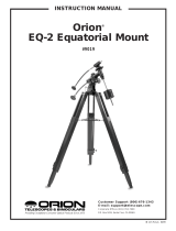
Figure 1a.
The StarBlast II 4.5 EQ
EZ Finder II reex sight
Eyepiece
Focuser
Tube rings
Optical tube
Primary mirror cell
Declination slow-motion control
Right ascension slow-motion control
Latitude adjustment T-bolt
Azimuth lock knob
Accessory tray
Declination setting circle
Right ascension setting circle
Counterweight lock knob
Counterweight
Counterweight shaft
Accessory tray
bracket
Leg lock knob
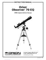
Figure 1b. The StarBlast II 4.5’s equatorial mount.
Right ascension
lock knob
Right ascension
setting circle
Latitude scale
Latitude lock T-bolt
Latitude adjustment
T-bolt
Declination lock knob
Declination
setting circle
Azimuth lock knob
Declination (Dec.) axis

3
Table of Contents
1. Unpacking 3
2. Parts List 3
3. Assembly 3
4. Getting Started 4
5. Setting Up and Using the
Equatorial Mount 7
6. Collimating the Optics 10
7. Astronomical Observing 11
8. Care and Maintenance 13
9. Specications 14
1. Unpacking
The entire telescope system will arrive in one box. Be careful
unpacking the box. We recommend keeping the original ship-
ping containers. In the event that the telescope needs to be
shipped to another location, or returned to Orion for warranty
repair, having the proper shipping containers will help ensure
your telescope will survive the journey intact.
Make sure all the parts in the Parts List are present. Be sure
to check boxes carefully, as some parts are small. If anything
appears to be missing or broken, immediately call Orion
Customer Support (800-676-1343) for assistance.
2. Parts List
Qty. Description
1 Optical tube assembly
2 Tube mounting rings
1 Equatorial mount
1 Latitude adjustment T-bolt
2 Slow-motion control cables
3 Tripod legs connected to accessory
tray bracket
1 Tripod accessory tray
1 Counterweight shaft
1 Counterweight
1 EZ Finder II reflex sight with mounting
bracket
1 25mm Sirius Plossl eyepiece
1 10mm Sirius Plossl eyepiece
1 Collimating cap
3. Assembly
Assembling the telescope for the first time should take
about 30 minutes. All screws should be tightened securely
to eliminate exing and wobbling, but be careful not to over-
tighten or the threads may strip. Refer to Figures 1a. and
1b. during assembly.
During assembly (and anytime, for that matter), do not touch the
surfaces of the telescope mirrors or the lenses of the EZ Finder II
or eyepieces with your ngers; the optical surfaces have coatings
on them that can be damaged. Never remove any lens assem-
bly from its housing for any reason, or the product warranty and
return policy will be void.
1. Lay the equatorial mount on its side. Attach the tripod legs
one at a time to the mount using the screws installed in
the tops of the tripod legs. Remove the screws, washers,
and wingnuts from the tripod legs, then line up the holes in
the tops of the tripod legs with the holes in the base of the
mount. Reinstall the screws so they pass through the legs
and the mount. Place one washer on each screw before
doing this. After the screws are though the legs and mount,
place a washer and wingnut on each screw end (Figure
2). Tighten the wingnuts only nger-tight, for now.
2. Tighten the leg lock knobs on the bottom braces of the
tripod legs. For now, keep the legs at their shortest (fully
retracted) length; you can extend them to a more desirable
length later, after the tripod is completely assembled.
Congratulations on your purchase of an Orion telescope.Your new StarBlast II 4.5 EQ is a terric starter
instrument for exploring the exotic wonders of the night sky. Designed to be compact and easy to use, it
will provide many hours of enjoyment for the whole family.
If you have never owned a telescope before, we would like to welcome you to amateur astronomy. Take
some time to familiarize yourself with the night sky. Learn to recognize the patterns of stars in the major
constellations. With a little practice, a little patience, and a reasonably dark sky away from city lights, you’ll
nd your telescope to be a never-ending source of wonder, exploration, and relaxation.
These instructions will help you set up, properly use, and care for your telescope. Please read them over
thoroughly before getting started.
WARNING: Never look directly at the Sun through
your telescope—even for an instant—without a
professionally made solar lter that completely
covers the front of the instrument, or permanent eye
damage could result. Young children should use this
telescope only with adult supervision.

4
3. Stand the tripod and mount upright and spread the tripod
legs apart as far as they will go, until the accessory tray
bracket is taut. Connect the accessory tray to the accesso-
ry tray bracket with the three wing screws. Do this by push-
ing the wing screws up through the holes in the acces-
sory tray bracket and threading them into the holes in the
accessory tray.
4. Next, tighten the screws at the tops of the tripod legs,
so the legs are securely fastened to the mount. Use the
Phillips head screwdriver and your ngers to do this.
5. Install the latitude adjustment T-bolt into the threaded hole
in the rear of the mount (Figure 3).
6. Orient the equatorial mount as it appears in Figure 1b. To
do this, rst loosen the latitude lock T-bolt, and turn the lati-
tude adjustment T-bolt until the latitude scale pointer and
the “40” on the latitude scale line up. Then retighten the lati-
tude lock T-bolt. The declination (Dec.) and right ascension
(R.A.) axes will need re-positioning (rotation) as well. Be
sure to loosen the R.A. and Dec. lock knobs before doing
this. Retighten the R.A. and Dec. lock knobs once the equa-
torial mount is oriented as shown in Figure 1b.
7. Thread the counterweight shaft into the equatorial mount
at the base of the declination axis until tight.
8. Remove the screw and washer on the bottom of the coun-
terweight shaft and slide the counterweight onto the shaft.
Make sure the counterweight lock knob is adequately
loosened to allow the counterweight shaft to pass through
the hole. Position the counterweight about halfway up the
shaft and tighten the lock knob. Replace the screw and
washer on the end of the shaft.
9. Attach the two tube rings to the equatorial mount using
the hex head screws that come installed in the rings.
Remove the screws, then push them, with the washers
still attached, up through the holes in the tube ring mount-
ing plate (on the top of the equatorial mount) and rethread
them into the bottom of the tube rings. Tighten the screws
securely with the included wrench. Open the tube rings by
loosening their knurled ring clamps.
10. Attach the two slow-motion control cables to the R.A. and
Dec. worm gear shafts of the equatorial mount by posi-
tioning the thumbscrew on the end of the cable over the
indented slot on the worm gear shaft and then tighten-
ing the thumbscrew. We recommend the shorter cable be
used on the R.A. worm gear shaft and the longer cable on
the Dec. worm gear shaft. You can install slow-motion con-
trol cable on either end of the R.A. worm gear shaft; use
whichever end is most convenient.
11. Before installing the EZ Finder II, see “Installing the
Battery in the EZ Finder II" in Section 4. Once the battery
is installed, loosen and remove the reex sight securing
thumbnuts on the optical tube near the focuser. Place the
holes in the base of the EZ Finder’s bracket over the two
threaded shafts coming out of the optical tube. Make sure
the EZ Finder II is oriented as in Figure 1a. Replace the
thumbnuts to secure the reex sight to the optical tube.
12. Remove the cap from the focuser and insert the 25mm
eyepiece into the focuser drawtube. Secure it in place with
the thumbscrews on the end of the drawtube.
Your StarBlast II 4.5 EQ is now fully assembled and should
resemble Figure 1a. Leave the dust cover on the front of the
optical tube when it is not in use.
4. Getting Started
Now that the StarBlast II 4.5 is assembled, the next things to do
are to balance the telescope about its axes of motion, and to
align the reex sight with the telescope.
Balancing the Telescope
To insure smooth movement of the telescope on both axes of the
equatorial mount, it is imperative that the optical tube be properly
balanced. First balance the telescope with respect to the R.A.
axis, then the Dec. axis.
Figure 2. Attach the tripod legs to the mount with the screws that
come installed in the tops of the tripod legs. One washer should go
between the screw head and tripod leg and the other washer should
go between the wingnut and tripod leg.
Figure 3. The latitude adjustment T-bolt goes into the threaded
hole in the rear of the mount.
Washer
Wingnut
Screw
head
Washer
Threaded hole
Latitude
adjustment T-bolt
Screw end

5
1. Keeping one hand on the telescope optical tube, loosen
the R.A. lock knob. Make sure the Dec. lock knob is locked,
for now. The telescope should now be able to rotate freely
about the R.A. axis. Rotate it until the counterweight shaft
is parallel to the ground (i.e., horizontal).
2. Now loosen the counterweight lock knob and slide the
weight along the shaft until it exactly counterbalances the
telescope (Figure 4a). That’s the point at which the shaft
remains horizontal even when you let go of the telescope
with both hands.
3. Retighten the counterweight lock knob. The telescope is
now balanced on the R.A. axis.
4. To balance the telescope on the Dec. axis, rst tighten
the R.A. lock knob, with the counterweight shaft still in the
horizontal position.
5. With one hand on the telescope optical tube, loosen the
Dec. lock knob. The telescope should now be able to rotate
freely about the Dec. axis (Figure 4b). Loosen the knurled
tube ring clamps a few turns, until you can slide the tele-
scope tube forward and back inside the rings Using a
slight twisting motion on the optical tube can help move
the tube within the rings.
6. Position the telescope so it remains horizontal when you
carefully let go with both hands. This is the balance point.
Before clamping the tube rings tight again, rotate the tele-
scope so the eyepiece is at a convenient angle for view-
ing. When you are actually observing with the telescope,
you can adjust the eyepiece position by loosening the tube
rings and rotating the optical tube.
7. Retighten the tube ring clamps.
The telescope is now balanced on both axes. Now when you
loosen the lock knob on one or both axes and manually point the
telescope, it should move without resistance and should not drift
from where you point it.
Focusing the Telescope
With the 25mm eyepiece in the focuser, move the telescope
so the front (open) end is pointing in the general direction of an
object at least 1/4-mile away. Now with your ngers, slowly rotate
one of the focusing knobs until the object comes into sharp
focus. Go a little bit beyond sharp focus until the image starts
to blur again, then reverse the rotation of the knob, just to make
sure you’ve hit the exact focus point.
Do You Wear Eyeglasses?
If you wear eyeglasses, you may be able to keep them on while
you observe. In order to do this, your eyepiece must have enough
“eye relief” to allow you to see the entire eld of view with glasses
on. You can try this by looking through the eyepiece rst with your
glasses on and then with them off, and see if the glasses restrict
the view to only a portion of the full eld. If the glasses do restrict
the eld of view, you may be able to observe with your glasses
off by just refocusing the telescope.
If your eyes are astigmatic, however, images will probably appear
better with glasses on. This is because a telescope’s focuser can
accommodate for nearsightedness or farsightedness, but not
astigmatism. If you have to wear your glasses while observing
and cannot see the entire eld of view, you may want to consider
purchasing special eyepieces that have extra-long eye relief.
Operating the EZ Finder II Reflex Sight
The EZ Finder II reex sight (Figure 5) makes pointing your
telescope almost as easy as pointing your nger! It’s a non-
magnifying aiming device that superimposes a tiny red dot on
the sky, showing exactly where the telescope is pointed.
Installing the Battery in the EZ Finder II
Before installing the EZ Finder II on the telescope, you will
need to insert the included CR2032 3V lithium button cell bat-
tery in the EZ Finder II. If there is a small plastic tab sticking
out from the battery compartment cover, you must remove it
for the battery to make contact with the EZ Finder’s electronic
circuitry. The tab can then be discarded.
1. Turn the EZ Finder II upside down as shown in Figure 6a.
2. Insert a small, at-blade screwdriver into the notch in the bat-
tery compartment cover and gently pry it off.
Figure 4.
Proper usage of the equatorial mount requires the telescope tube to be balanced on both the R.A. and Dec. axes. (a) With the
R.A. lock knob released, slide the counterweight along the counterweight shaft until it just counterbalances the tube. When you let go with
both hands, the tube should not drift up or down. (b) With the Dec. lock knob released, loosen the tube ring lock clamps a few turns and
slide the telescope forward or back in the tube rings. When the tube is balanced about the Dec. axis, it will not move when you let go.
b.
a.
RA lock knob
Dec. lock knob
Tube ring clamps

6
3. Slide the battery under the retaining clip with the positive (+)
side facing up (touching the clip) (6b).
4. Then press the battery compartment cover back on. Should
the battery die, replacement CR2032 batteries are available at
many stores where small batteries are sold or online.
The EZ Finder II works by projecting a tiny red dot (it’s not a
laser beam) onto a lens mounted in the front of the unit. When
you look through the EZ Finder II, the red dot will appear to
oat in space, helping you locate even the faintest of deep-sky
objects (Figure 7). The red dot is produced by a light-emitting
diode (LED) near the rear of the sight.
Turn the power knob clockwise until you hear the “click” indicat-
ing power has been turned on. Look through the rear of the
reex sight with both eyes open to see the red dot. Position your
eye at a comfortable distance from the rear of the sight. The
intensity of the dot is adjusted by turning the power knob. For
best results when stargazing, use the dimmest possible setting
that allows you to see the dot without difficulty. Typically a dimmer
setting is used under dark skies and a brighter setting is used
under light-polluted skies or daylight.
At the end of your observing session, be sure to turn the power
knob counterclockwise until it clicks off. When the white dots
on the reex sight’s body and power knob are lined up, the EZ
Finder II is turned off.
Aligning the EZ Finder II Reflex Sight
When the EZ Finder II is properly aligned with the telescope, an
object that is centered on the reex sight’s red dot should also
appear in the center of the eld of view of the telescope’s eye-
Retaining clip
Battery
compartment
cover
Notch
Naked-eye view
Figure 8. The view through a reector telescope is rotated 180°
View through telescope
Figure 5. The EZ Finder II reex sight.
Power Knob
Azimuth
adjustment
Knob
Battery
compartment
cover
Mounting bracket
Altitude
adjustment
Knob
Figure 6. a) To install the CR2032 battery in the EZ Finder II, rst
turn it upside-down and remove the battery compartment cover.
b) Install the battery with positive (+) side facing up, as shown.
Figure 7. The EZ Finder II superimposes a small red dot (it’s not
a laser!) on a non-magnied eld of view, which helps to center an
object in the telescope’s eld of view.
b.
a.

7
piece. Alignment of the EZ Finder II is easiest during daylight,
before observing at night. Aim the telescope at a distant object
such as a telephone pole or roof chimney and center it in the
telescope’s eyepiece. The object should be at least 1/4 mile away.
Now, with the EZ Finder turned on, look though the EZ Finder II.
The object will appear in the eld of view near the red dot.
Note: The image in the telescope will appear upside-down
(rotated 180°). This is normal for reector telescopes (Figure 8).
Without moving the telescope, use the reex sight’s azimuth (left/
right) and altitude (up/down) adjustment knobs to position the
red dot on the object in the eyepiece.
When the red dot is centered on the distant object, check to make
sure the object is still centered in the telescope’s eld of view. If not,
re-center it and adjust the reex sight’s alignment again. When the
object is centered in the eyepiece and on the reex sight’s red dot,
the EZ Finder II is properly aligned with the telescope.
The reex sight’s alignment should be checked before every
observing session. Choose any bright star or planet, center the
object in the telescope’s eyepiece, then adjust the knobs until the
object is centered on the red dot of the EZ Finder II.
5. Setting Up and Using the
Equatorial Mount
When you look at the night sky, you no doubt have noticed the
stars appear to move slowly from east to west over time. That
apparent motion is caused by the Earth’s rotation (from west to
east). An equatorial mount (Figure 1b) is designed to compen-
sate for that motion, allowing you to easily “track” the movement
of astronomical objects, thereby keeping them from drifting out of
the telescope’s eld of view while you’re observing.
This is accomplished by slowly rotating the telescope on its right
ascension (R.A.) axis, using only the R.A. slow-motion cable. But
rst the R.A. axis of the mount must be aligned with the Earth’s
rotational (polar) axis—a process called polar alignment.
Polar Alignment
For Northern Hemisphere observers, approximate polar align-
ment is achieved by pointing the mount’s right ascension axis
at the North Star (Polaris). It lies within 1° of the north celes-
tial pole (NCP), which is an extension of the Earth’s rotational
axis out into space. Stars in the Northern Hemisphere appear
to revolve around the NCP.
To nd Polaris in the sky, look north and locate the pattern of the
Big Dipper (Figure 9). The two stars at the end of the “bowl” of
the Big Dipper point right to Polaris.
Observers in the Southern Hemisphere aren’t so fortunate to
have a bright star so near the south celestial pole (SCP). The
star Sigma Octantis lies about 1° from the SCP, but it is barely
visible with the naked eye (magnitude 5.5).
To polar align the StarBlast II 4.5 EQ:
1. Level the equatorial mount by adjusting the length of the
three tripod legs.
2. Loosen the latitude lock T-bolt. Turn the latitude adjust-
ment T-bolt until the pointer on the latitude scale is indicat-
ing the latitude of your observing site. If you don’t know
your latitude, consult a geographical atlas to nd it. For
example, if your latitude is 35° North, set the pointer to 35.
Then retighten the latitude lock T-bolt. The latitude setting
should not have to be adjusted again unless you move to a
different viewing location some distance away.
3. Loosen the Dec. lock knob and rotate the telescope optical
tube until it is parallel with the R.A. axis, as it is in Figure
1a. The pointer on the Dec. setting circle should read 90°.
Retighten the Dec. lock lever.
4. Loosen the azimuth lock knob at the base of the equa-
torial mount and rotate the mount so the telescope tube
(and R.A. axis) points roughly at Polaris. If you cannot see
Polaris directly from your observing site, consult a com-
pass and rotate the mount so the telescope points North.
Retighten the azimuth lock knob.
The equatorial mount is now polar aligned. From this point on in
your observing session, you should not make any further adjust-
ments to the azimuth or the latitude of the mount, nor should
you move the tripod. Doing so will undo the polar alignment. The
telescope should be moved only about its R.A. and Dec. axes.
Use of the R.A. and Dec. Slow-Motion Control
Cables
The R.A. and Dec. slow-motion control cables allow ne adjust-
ment of the telescope’s position to center objects within the eld
of view. Before you can use the cables, you must manually “slew”
the mount to point the telescope in the vicinity of the desired tar-
get. Do this by loosening the R.A. and Dec. lock knobs and mov-
ing the telescope about the mount’s R.A. and Dec. axes. Once
the telescope is pointed somewhere close to the object to be
viewed, retighten the mount’s R.A. and Dec. lock knobs.
The object should now be visible somewhere in the EZ Finder
II. If it isn’t, use the slow-motion controls to scan the surrounding
area of sky. When the object is visible in the EZ Finder II, use the
slow-motion controls to center the red dot on it. Now, look in the
Big Dipper
(in Ursa Major)
Little Dipper
(in Ursa Minor)
Cassiopeia
N.C.P.
Pointer
Stars
Polaris
Figure 9. To nd Polaris in the night sky, look north and nd the
Big Dipper. Extend an imaginary line from the two "Pointer Stars"
in the bowl of the Big Dipper. Go about ve times the distance
between those stars and you'll reach Polaris, which lies within 1° of
the north celestial pole (NCP).

8
telescope’s eyepiece. If the EZ Finder II is properly aligned, the
object should be visible somewhere in the eld of view. Once the
object is visible in the eyepiece, use the slow-motion controls to
center it in the eld of view.
The Dec. slow-motion control cable can move the telescope a
maximum of 25°. This is because the Dec. slow-motion mecha-
nism has a limited range of mechanical travel. (The R.A. slow-
motion mechanism has no limit to its amount of travel.) If you
can no longer rotate the Dec. control cable in a desired direc-
tion, you have reached the end of travel, and the slow-motion
mechanism must be reset. This is done by rst rotating the con-
trol cable several turns in the opposite direction from which it was
being turned. Then, manually slew the telescope closer to the
object you wish to observe (remember to rst loosen the Dec.
lock knob). You should now be able to use the Dec. slow-motion
control cable again to ne adjust the telescope’s position.
Tracking Celestial Objects
When you observe a celestial object through the telescope, you’ll
see it drift slowly across the eld of view. To keep it in the eld,
assuming your equatorial mount is polar aligned, just turn the
R.A. slow-motion control cable clockwise. The Dec. slow-motion
control cable is not needed for tracking. Objects will appear to
move faster at higher magnications, because the eld of view
is narrower.
Optional Electronic Drives for Automatic
Tracking
An optional DC electronic drive can be mounted on the R.A. axis
of the equatorial mount to provide hands-free tracking. Objects
will then remain stationary in the eld of view without any manual
adjustment of the R.A. slow-motion control cable.
Understanding the Setting Circles
The setting circles on an equatorial mount enable you to
locate celestial objects by their “celestial coordinates”. Every
object resides in a specic location on the “celestial sphere”.
That location is denoted by two numbers: its right ascension
(R.A.) and declination (Dec.). In the same way, every location
on Earth can be described by its longitude and latitude. R.A.
is similar to longitude on Earth, and Dec. is similar to latitude.
The R.A. and Dec. values for celestial objects can be found in
any star atlas or star catalog.
The mount’s R.A. setting circle is scaled in hours, from 1 through
24, with small marks in between representing 10-minute incre-
ments. The numbers closest to the R.A. axis gear apply to view-
ing in the Southern Hemisphere, while the numbers above them
apply to viewing in the Northern Hemisphere.
The Dec. setting circle is scaled in degrees, with each mark rep-
resenting 2.5° increments. Values of Dec. coordinates range from
+90° to -90°. The 0° mark indicates the celestial equator. When
the telescope is pointed north of the celestial equator, values of
the Dec. setting circle are positive, while when the telescope is
pointed south of the celestial equator, values of the Dec. setting
circle are negative.
So, the coordinates for the Orion Nebula listed in a star atlas will
look like this:
R.A. 5h 35.4m Dec. -5° 27’
That’s 5 hours and 35.4 minutes in right ascension, and -5
degrees and 27 arc-minutes in declination (there are 60 arc-min-
utes in 1 degree of declination).
Before you can use the setting circles to locate objects, the
mount must be properly polar aligned, and the R.A. setting circle
must be calibrated. The Dec. setting circle has been permanently
calibrated at the factory, and should read 90° whenever the tele-
scope optical tube is parallel with the R.A. axis.
Calibrating the Right Ascension Setting Circle
1. Identify a bright star in the sky near the celestial equator
(Dec. = 0°) and look up its coordinates in a star atlas.
2. Loosen the R.A. and Dec. lock knobs on the equatorial
mount, so the telescope optical tube can move freely.
3. Point the telescope at the bright star whose coordinates
you know. Lock the R.A. and Dec. lock knobs. Center the
star in the telescope’s eld of view with the slow-motion
control cables.
4. Rotate the setting circle until the metal arrow indicates the
R.A. coordinate listed in the star atlas for the object.
Finding Objects with the Setting Circles
1. Now that both setting circles are calibrated, look up in a
star atlas the coordinates of an object you wish to view.
2. Loosen the R.A. lock knob and rotate the telescope until
the R.A. value from the star atlas matches the reading on
the R.A. setting circle. Remember to use the upper set
of numbers on the R.A. setting circle. Retighten the lock
knob.
3. Loosen the Dec. lock knob and rotate the telescope until
the Dec. value from the star atlas matches the reading on
the Dec. setting circle. Remember that values of the Dec.
setting circle are positive when the telescope is pointing
north of the celestial equator (Dec. = 0°), and negative
when the telescope is pointing south of the celestial equa-
tor. Retighten the lock knob.
Most setting circles are not accurate enough to put an object
dead-center in the telescope’s eyepiece, but they should place
the object somewhere within the eld of view of the EZ Finder II,
assuming the equatorial mount is accurately polar aligned. Use
the slow-motion controls to center the object in the reex sight,
and it should appear in the telescope’s eld of view.
The R.A. setting circle must be re-calibrated every time you wish
to locate a new object. Do so by calibrating the setting circle for
the centered object before moving on to the next one.
Confused About Pointing the Telescope?
Beginners occasionally experience some confusion about how
to point the telescope overhead or in other directions. In Figure
1a the telescope is pointed north, as it would be during polar
alignment. The counterweight shaft is oriented downward. But
it will not look like that when the telescope is pointed in other
directions. Let’s say you want to view an object that is directly
overhead, at the zenith. How do you do it?

9
One thing you DO NOT do is make any adjustment to the latitude
adjustment T-bolt. That will nullify the mount’s polar alignment.
Remember, once the mount is polar aligned, the telescope should
be moved only on the R.A. and Dec. axes. To point the scope
overhead, rst loosen the R.A. lock knob and rotate the telescope
on the R.A. axis until the counterweight shaft is horizontal (paral-
lel to the ground). Then loosen the Dec. lock knob and rotate the
telescope until it is pointing straight overhead. The counterweight
shaft is still horizontal. Then retighten both lock knobs.
Similarly, to point the telescope directly south, the counterweight
shaft should again be horizontal. Then you simply rotate the
scope on the Dec. axis until it points in the south direction.
What if you need to aim the telescope directly north, but at an
object that is nearer to the horizon than Polaris? You can’t do it
with the counterweight down as pictured in Figure 1a. Again,
you have to rotate the scope in R.A. so the counterweight shaft is
positioned horizontally. Then rotate the scope in Dec. so it points
to where you want it near the horizon.
Figure 10. This illustration show the telescope pointed in the four cardinal directions (a) north (b) south (c) east (d) west. Note that the
tripod and mount have not been moved; only the telescope tube has been moved in the R.A. and Dec. axes.
a b c d
Figure 11. Collimating the optics. (a) When the mirrors are properly aligned, the view down the focuser drawtube should
look like this.
(b) With the collimation cap in place, if the optics are out of alignment, the view might look something like this.
(c) Here, the secondary mirror is centered under the focuser, but it needs to be adjusted (tilted) so that the entire primary
mirror is visible.
(d) The secondary mirror is correctly aligned, but the primary mirror still needs adjustment. When the primary
mirror is correctly aligned, the “dot” will be centered, as in
(e).
a.
Primary mirror
center mark
Reflective surface
of collimation
cap
b.
c.
d.
e.

10
To point the telescope to the east or west, or in other direc-
tions, you rotate the telescope on its R.A. and Dec. axes.
Depending on the altitude of the object you want to observe,
the counterweight shaft will be oriented somewhere between
vertical and horizontal.
Figure 10 illustrates how the telescope will look pointed at the
four cardinal directions—north, south, east, and west
The key things to remember when pointing the telescope is
that a) you only move it in R.A. and Dec., not in azimuth or
latitude (altitude), and b) the counterweight and shaft will not
always appear as it does in Figure 1a. In fact, it almost never
will!
6. Collimating the Optics
Collimating is the process of adjusting the mirrors so they are
aligned with one another. Your telescope’s optics were aligned
at the factory, and should not need much adjustment unless
the telescope is handled roughly. Accurate mirror alignment is
important to ensure peak performance of your telescope, so
it should be checked regularly. Collimating is relatively easy to
do and can be done in daylight.
To check optical alignment, remove the eyepiece and look
down the focuser drawtube. You should see the secondary
mirror centered in the drawtube, as well as the reection of
the primary mirror centered in the secondary mirror, and the
reection of the secondary mirror (and your eye) centered in
the reection of the primary mirror, as in Figure 11a. If any-
thing is off-center, proceed with the following collimating pro-
cedure.
The Collimating Cap and Primary
Mirror Center Mark
Your StarBlast II 4.5 EQ comes with a collimating cap (Figure
12).This is a simple cap that ts on the focuser drawtube like a
dust cap, but has a hole in the center and a light, reective sur-
face on the underside. This helps center your eye so collimating
is easy to perform. Figures 11b through 11e assume you have
the collimating cap in place.
In addition to the collimating cap, you’ll notice a small ring label
on the exact center of the primary mirror. This “center mark”
allows you to achieve a very precise alignment of the primary
mirror; you don’t have to guess where the center of the mirror is.
Aligning the Secondary Mirror
It helps to adjust the secondary mirror in a brightly lit room with
the telescope pointed toward a bright surface, such as white
paper or wall. Placing a piece of white paper in the telescope
tube opposite the focuser (i.e. behind the secondary mirror) will
also be helpful in collimating the secondary mirror.
With the collimating cap in place, look through the hole in the cap
at the secondary (diagonal) mirror. Ignore the reections for the
time being. The secondary mirror itself should be centered in the
focuser drawtube,. If it isn’t, as in Figure 11b, it must be adjust-
ed. Typically, this adjustment will rarely, if ever, need to be done.
Note: When making adjustments to the secondary mirror posi-
tion, be careful not to stress the spider vanes, or they may bend.
To adjust the secondary mirror left-to-right in the focuser draw-
tube, use a 2.5mm hex key to loosen the three small alignment
setscrews in the center hub of the 4-vaned spider several turns.
Now hold the mirror holder stationary (be careful not to touch
the surface of the mirror), while turning the center screw with a
Phillips head screwdriver (Figure 13). Turning the screw clock-
wise will move the secondary mirror toward the front opening of
the optical tube, while turning the screw counter-clockwise will
move the secondary mirror toward the primary mirror. When the
secondary mirror is centered left-to-right in the focuser drawtube,
rotate the secondary mirror holder until the reection of the pri-
mary mirror is as centered in the secondary mirror as possible. It
may not be perfectly centered, but that is OK for now. Tighten the
three small alignment setscrews equally to secure the secondary
mirror in that position.
If the entire primary mirror reection is not visible in the second-
ary mirror, as in Figure 11c, you will need to adjust the tilt of the
secondary mirror. This is done by alternately loosening one of
Figure 14.
Adjust the tilt of
the secondary
mirror by
loosening one
of the three
alignment set
screws then
tightening the
other two.
Alignment set screws (3)
Figure 12. The
quick collimation
cap, which features
a reective inner
surface, helps in
centering reections
of the optics in the
focuser during the
collimation process.
Figure 13.
To center the
secondary mirror
under the focuser,
hold the secondary
mirror holder in
place with your
ngers while
adjusting the
center screw with
the Phillips head
screwdriver. Do not
touch the mirror’s
surface.

11
the three alignment setscrews while tightening the other two, as
depicted in Figure 14. You will need a 2.5mm hex key to do this.
The goal is to center the primary mirror reection in the second-
ary mirror, as in Figure 11d. Don’t worry that the reection of the
secondary mirror within the primary mirror reection (the small-
est circle, with the collimation cap “dot” in the center) is off-center.
You will x that in the next step.
Once the secondary mirror is centered in the focuser drawtube,
and the primary mirror reection is centered in the secondary
mirror, the secondary mirror is properly aligned, and no further
adjustments to it should be needed.
Aligning the Primary Mirror
The nal adjustment is made to the primary mirror. It will need
adjustment if, as in Figure 11d, the secondary mirror is centered
in the focuser drawtube and the reection of the primary mirror
is centered in the secondary mirror, but the small reection of
the secondary mirror (with the “dot” of the collimating cap) is off-
center.
The tilt of the primary mirror is adjusted with the three large
knurled thumbscrews on the rear end of the optical tube (back of
the mirror cell) (Figure 15). The small thumbscrews (with slots in
them) serve to lock the mirror in place. Start by loosening each
of these smaller thumbscrews a few turns. Use a screwdriver in
the slots, if necessary. Now adjust the tilt of the primary mirror by
turning one of the large thumbscrews either clockwise or coun-
terclockwise. Look into the focuser and see if the secondary mir-
ror reection has moved closer to the center of the primary mirror
reection. You can determine this easily with the collimating cap
and primary mirror center mark by simply watching to see if the
“dot” of the collimating cap is moving closer or farther away from
the “ring” on the primary mirror. If it isn’t getting closer, try turning
the thumbscrew in the opposite direction. Repeat this process for
the other two large thumbscrews, if necessary. It will take a little
trial-and-error to get the feel for how to adjust the primary mirror
to center the dot of the collimating cap in the ring of the primary
mirror center mark.
When you have the dot centered as much as possible in the ring,
your primary mirror is aligned. The view through the collimating
cap should resemble Figure 11e. Make sure the smaller thumb-
screws on the back of the mirror cell are tightened to lock the
primary mirror in position.
A simple star test will tell you whether the optics are, in fact,
accurately aligned.
Star-Testing the Telescope
When it is dark, point the telescope at a bright star and accu-
rately center it in the eyepiece’s eld of view. Slowly de-focus the
image with the focus knob. If the telescope’s optics are correctly
aligned, the expanding disk should be a perfect circle (Figure
16). If the image is unsymmetrical, the optics are out of align-
ment. The dark shadow cast by the secondary mirror should
appear in the very center of the out-of-focus circle, like the hole
in a donut. If the “hole” appears off-center, the optics are out of
alignment.
If you try the star test and the bright star you have selected
is not accurately centered in the eyepiece, the telescope will
appear to need collimating, even though the optics may be
perfectly aligned. It is critical to keep the star centered, so over
time you will need to make slight corrections to the telescope’s
position in order to account for the sky’s apparent motion.
7. Astronomical Observing
For many, this will be the rst foray into the exciting world of ama-
teur astronomy. The following information and observing tips will
help get you started.
Choosing an Observing Site
When selecting a location for observing, get as far away as pos-
sible from direct articial light such as street lights, porch lights,
and automobile headlights. The glare from these lights will great-
ly impair your dark-adapted night vision. Set up on a grass or
dirt surface, not asphalt, because asphalt radiates more heat.
Heat disturbs the surrounding air and degrades the images seen
through the telescope. Avoid viewing over rooftops and chimneys,
as they often have warm air currents rising from them. Similarly,
avoid observing from indoors through an open (or closed) win-
dow, because the temperature difference between the indoor
and outdoor air will cause image blurring and distortion.
If at all possible, escape the light-polluted city sky and head for
darker country skies. You’ll be amazed at how many more stars
and deep-sky objects are visible in a dark sky!
Figure 16. A star
test will determine
if the telescope's
optics are properly
collimated. An
unfocused view of a
bright star through
the eyepiece
should appear
as illustrated on the right if optics are perfectly collimated. If the
circle is unsymmetrical, as illustrated on the left, the scope needs
collimation.
Out of collimation Collimated
Figure 15. The
tilt of the primary
mirror is adjusted
by turning the three
larger thumbscrews.

12
“Seeing” and Transparency
Atmospheric conditions vary signicantly from night to night.
“Seeing” refers to the steadiness of the Earth’s atmosphere at a
given time. In conditions of poor seeing, atmospheric turbulence
causes objects viewed through the telescope to “boil”. If you look
up at the sky and stars are twinkling noticeably, the seeing is
poor and you will be limited to viewing at lower magnications. At
higher magnications, images will not focus clearly. Fine details
on the planets and Moon will likely not be visible.
In conditions of good seeing, star twinkling is minimal and
images appear steady in the eyepiece. Seeing is best overhead,
worst at the horizon. Also, seeing generally gets better after mid-
night, when much of the heat absorbed by the Earth during the
day has radiated off into space.
Especially important for observing faint objects is good “trans-
parency”—air free of moisture, smoke, and dust. All tend to scat-
ter light, which reduces an object’s brightness. Transparency is
judged by the magnitude of the faintest stars you can see with
the unaided eye (6th magnitude or fainter is desirable).
Cooling the Telescope
All optical instruments need time to reach “thermal equilibri-
um.” The bigger the instrument and the larger the temperature
change, the more time is needed. Allow at least 30 minutes for
your telescope to acclimate to the temperature outdoors before
you start observing with it.
Let Your Eyes Dark-Adapt
Don’t expect to go from a lighted house into the darkness of the
outdoors at night and immediately see faint nebulas, galaxies,
and star clusters—or even very many stars, for that matter. Your
eyes take about 30 minutes to reach perhaps 80% of their full
dark-adapted sensitivity. As your eyes become dark-adapted,
more stars will glimmer into view and you’ll be able to see fainter
details in objects you view in your telescope.
To see what you’re doing in the darkness, use a red-ltered ash-
light rather than a white light. Red light does not spoil your eyes’
dark adaptation like white light does. A ashlight with a red LED
light is ideal, or you can cover the front of a regular incandescent
ashlight with red cellophane or paper. Beware, too, that nearby
porch, streetlights, and car headlights will ruin your night vision.
Eyepiece Selection
Magnication, or power, is determined by the focal length of
the telescope and the focal length of the eyepiece being used.
Therefore, by using eyepieces of different focal lengths, the
resultant magnication can be varied. It is quite common for an
observer to own ve or more eyepieces to access a wide range
of magnications. This allows the observer to choose the best
eyepiece to use depending on the object being viewed and view-
ing conditions. The StarBlast II 4.5 EQ comes with two eyepiec-
es, which will suffice nicely to begin with.
Magnication is calculated as follows:
Telescope Focal Length (mm)
= Magnication
Eyepiece Focal Length (mm)
For example, the StarBlast II 4.5 EQ has a focal length of 450mm,
which when used with the supplied 15mm eyepiece yields:
450 mm
= 18x
25 mm
The magnication provided by the 6mm eyepiece is:
450 mm
= 45x
10 mm
The maximum attainable magnication for a telescope is directly
related to how much light it can gather. The larger the aperture,
the more magnication is possible. In general, a gure of 50x per
inch of aperture is the maximum attainable for most telescopes.
Your StarBlast II 4.5 EQ has an aperture of 4.5 inches, so the
maximum magnication would be about 225x. This level of mag-
nication assumes you have ideal conditions for observing.
Keep in mind that as you increase magnication, the brightness
of the object viewed will decrease; this is an inherent principle
of the laws of physics and cannot be avoided. If magnication is
doubled, an image appears four times dimmer. If magnication is
tripled, image brightness is reduced by a factor of nine!
Start by centering the object you wish to see in the 25mm eye-
piece. Then you may want to increase the magnication to get a
closer view. If the object is off-center (i.e., it is near the edge of
the eld of view) you will lose it when you increase magnication,
since the eld of view will be narrower with the higher-powered
eyepiece.
To change eyepieces, rst loosen the securing thumbscrews on
the focuser drawtube. Then carefully lift the eyepiece out of the
drawtube. Do not tug or pull the eyepiece to the side, as this
will knock the telescope off its target. Replace the eyepiece with
the new one by sliding it gently into the drawtube. Re-tighten the
thumbscrews, and refocus for your new magnication.
What to Expect
So what will you see with your telescope? You should be able to
see bands on Jupiter, the rings of Saturn, craters on the Moon,
the waxing and waning of Venus, and many bright deep-sky
objects. Do not expect to see color as you do in NASA photos,
since those are taken with long-exposure cameras and have
“false color” added. Our eyes are not sensitive enough to see
color in deep-sky objects except in a few of the brightest ones.
Objects to Observe
Now that you are all set up and ready to go, one critical decision
must be made: what to look at?
A. The Moon
With its rocky surface, the Moon is one of the easiest and most
interesting objects to view with your telescope. Lunar craters,
maria, and even mountain ranges can all be clearly seen from
a distance of 238,000 miles away! With its ever-changing phas-

13
es, you’ll get a new view of the Moon every night. The best time
to observe our one and only natural satellite is during a partial
phase, that is, when the Moon is not full. During partial phases,
shadows are cast on the surface, which reveal more detail, espe-
cially right along the border between the dark and light portions
of the disk (called the “terminator”). A full Moon is too bright and
devoid of surface shadows to yield a pleasing view. Make sure
to observe the Moon when it is well above the horizon to get the
sharpest images.
Use an optional Moon lter to dim the Moon when it is very
bright. It simply threads onto the bottom of the eyepieces (you
must rst remove the eyepiece from the focuser to attach a lter).
You’ll nd that the Moon lter improves viewing comfort, and also
helps to bring out subtle features on the lunar surface.
B. The Planets
The planets don’t stay put like the stars, so to nd them you
should refer to to the monthly starr charts at OrionTelescopes.
com, or to charts published monthly in Astronomy, Sky &
Telescope, or other astronomy magazines. Venus, Mars, Jupiter,
and Saturn are the brightest objects in the sky after the Sun and
the Moon. Other planets may be visible but will likely appear
star-like. Because planets are quite small in apparent size,
optional higher-power eyepieces are recommended and often
needed for detailed observations.
B. The Sun
You can change your nighttime telescope into a daytime Sun
viewer by installing an optional full-aperture solar lter over the
front opening of the StarBlast II 4.5 EQ. The primary attraction is
sunspots, which change shape, appearance, and location daily.
Sunspots are directly related to magnetic activity in the Sun.
Many observers like to make drawings of sunspots to monitor
how the Sun is changing from day to day.
Important Note: Do not look at the Sun with any optical
instrument without a professionally made solar lter, or per-
manent eye damage could result.
D. The Stars
Stars will appear like twinkling points of light. Even powerful
telescopes cannot magnify stars to appear as more than a point
of light. You can, however, enjoy the different colors of the stars
and locate many pretty double and multiple stars. The famous
“Double-Double” in the constellation Lyra and the gorgeous two-
color double star Albireo in Cygnus are favorites. Defocusing a
star slightly can help bring out its color.
E. Deep-Sky Objects
Under dark skies, you can observe a wealth of fascinating deep-
sky objects, including gaseous nebulas, open and globular star
clusters, and a variety of different types of galaxies. Most deep-
sky objects are very faint, so it is important you nd an observing
site well away from light pollution.
To nd deep-sky objects with your telescope, you rst need to
become reasonably familiar with the night sky. Unless you know
how to recognize the constellation Orion, for instance, you won’t
have much luck locating the Orion Nebula. A simple planisphere,
or star wheel, can be a valuable tool for learning the constella-
tions and seeing which ones are visible in the sky on a given
night. Once you have identied a few constellations, a good star
chart or atlas will come in handy for helping locate interesting
deep-sky objects to view within the constellations.
Do not expect these objects to appear like the photographs you
see in books and magazines; most will look like dim gray smudg-
es. Our eyes are not sensitive enough to see color in deep-sky
objects except in a few of the brightest ones. But as you become
more experienced and your observing skills get sharper, you will
be able to ferret out more and more subtle details and structure.
8. Care and Maintenance
If you give your telescope reasonable care, it will last a lifetime.
Store it in a clean, dry, dust-free place, safe from rapid changes
in temperature and humidity. Do not store the telescope out-
doors, although storage in a garage or shed is OK. Small compo-
nents like eyepieces and other accessories should be kept in a
protective box or storage case. Keep the dust cover on the front
of the telescope when it is not in use.
Your StarBlast II 4.5 EQ requires very little mechanical mainte-
nance. The optical tube has a smooth painted nish that is fairly
scratch-resistant. If a scratch does appear on the tube, it will not
harm the telescope. If you wish, you may apply some auto touch-
up paint to the scratch. Smudges on the tube can be wiped off
with a soft cloth and household cleaning uid.
Cleaning Optics
Any quality optical lens cleaning tissue and optical lens cleaning
uid specically designed for multi-coated optics can be used to
clean the exposed lenses of your eyepieces. Never use regular
glass cleaner or cleaning uid designed for eyeglasses. Before
cleaning, remove any loose particles or dust from the lens with
a blower bulb or soft brush. Then apply some cleaning uid to a
tissue, never directly on the optics. Wipe the lens gently in a cir-
cular motion, then remove any excess uid with a fresh lens tis-
sue. Oily ngerprints and smudges may be removed using this
method. Use caution; rubbing too hard may scratch the lens. On
larger lenses, clean only a small area at a time, using a fresh
lens tissue on each area. Never reuse tissues.
You should not have to clean the telescope’s mirrors very often,
if ever. Covering the front opening of the telescope with the dust
cover when it is not in use will prevent dust from accumulating on
the mirrors. Small specks of dust or ecks of paint have virtually
no effect on the visual performance of the telescope.
You should rarely if ever have to clean the telescope’s mirrors.
Covering the telescope with the dust cap when it is not in use will
help prevent dust from accumulating on the mirrors. Light dust or
other particles on the mirrors have virtually no effect on the visual
performance of the telescope. Improper cleaning can scratch
mirror coatings. If either mirror does need cleaning please
email us at: [email protected] or contact Orion Technical
Support at (800) 676-1343 to learn the correct procedure.
When bringing the telescope inside after an evening’s viewing it
is normal for moisture to accumulate on the mirrors and lenses
due to the change in temperature. We suggest leaving the tele-
scope and eyepieces uncovered overnight to allow the conden-
sation to evaporate.

14
9. Specifications
Primary mirror: 4.5" (114mm) diameter, parabolic, center marked
Effective focal length: 450mm
Focal ratio: f/3.9
Minor axis of secondary mirror: 1.3" (34mm)
Mirror coatings: Aluminum with silocon dioxide (SiO2) overcoat
Focuser: Rack-and-pinion, accepts 1.25" eyepieces
Eyepieces: 25mm and 10mm Sirius Plossl eyepieces, fully coat-
ed with multi-coatings, 1.25" barrel diameter, threaded for Orion
lters
Eyepiece magnication: 18x (with 25mm eyepiece) and 75x
(with 10mm eyepiece)
Finder scope: EZ Finder II reex sight
Mount: EQ-1, German equatorial
Tripod: Aluminum
Motor drives: Optional
Total instrument weight: 17 lbs.
One-Year Limited Warranty
This Orion product is warranted against defects in materials or workmanship for a period of one year from the date
of purchase. This warranty is for the benet of the original retail purchaser only. During this warranty period Orion
Telescopes & Binoculars will repair or replace, at Orion’s option, any warranted instrument that proves to be defec-
tive, provided it is returned postage paid. Proof of purchase (such as a copy of the original receipt) is required. This
warranty is only valid in the country of purchase.
This warranty does not apply if, in Orion’s judgment, the instrument has been abused, mishandled, or modied, nor
does it apply to normal wear and tear. This warranty gives you specic legal rights. It is not intended to remove or
restrict your other legal rights under applicable local consumer law; your state or national statutory consumer rights
governing the sale of consumer goods remain fully applicable.
For further warranty information, please visit www.OrionTelescopes.com/warranty.
Orion
®
Telescopes & Binoculars
Corporate Offices: 89 Hangar Way, Watsonville CA 95076 - USA
Customer Support: www.OrionTelescopes.com/contactus
Copyright © 2017 Orion Telescopes & Binoculars
All Rights Reserved. No part of this product instruction or any of its contents may be reproduced, copied, modified or adapted, without the prior
written consent of Orion Telescopes & Binoculars.
/