Page is loading ...

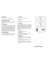
User Manual
Industrial Gigabit Switch
4-Port 802.3at PoE
with 2-port SFP slot
v1.0

FCC MARKING
This Equipment has been tested and found to comply with the limits for a
Class A digital device, pursuant to part 15 of the FCC Rules. These limits are
designed to provide reasonable protection against harmful interference when
the equipment is operated in a commercial environment. This equipment
generates, uses, and can radiate radio frequency energy and, if not installed
and used in accordance with the instruction manual, may cause harmful
interference to radio communications.
Operation of this equipment in a residential area is likely to cause harmful
interference in which case the user will be required to correct the interference
at his own expense.
This device complies with Part 15 of the FCC Rules. Operation is subject to
the following two conditions: (1) this device may not cause harmful
interference, and (2) this device must accept any interference received;
including interference that may cause undesired operation.
CE MARKING
This equipment complies with the requirements relating to electromagnetic
compatibility, EN 55022 class A for ITE, the essential protection requirement of
Council Directive 2004/108/EC on the approximation of the laws of the
Member States relating to electromagnetic compatibility.
Company has an on-going policy of upgrading its products and it may be
possible that information in this document is not up-to-date. Please check with
your local distributors for the latest information. No part of this document can
be copied or reproduced in any form without written consent from the company.
Trademarks:
All trade names and trademarks are the properties of their respective
companies.
Copyright © 2013, All Rights Reserved.
(P/N: 41NE-IPG40212-A00)

Introduction
The Industrial Ethernet Switch with PoE+ feature complies with IEEE802.3af
and IEEE802.3at. It delivers 30watts power per PoE port and generates a total
of 120 watts power to PD devices and 2 SFP slots are supported.
The Industrial Ethernet Switch provides wide power input voltage range +12 ~
+ 55Vdc, it not only boosts up Input Voltage, but also reduces the excessive
heat problem to a minimum ,and that secures equipment against unregulated
voltage and makes systems safer and more reliable.
The protection of IP-30 standard industrial case allows for either DIN rail or
wall mounting for efficient use of cabinet space. Its wide operating temperature
ranges from -40°C to 75°C under harsh environment.
Key Features
Supports P.S.E. based on IEEE 802.3at up to 30 Watts per port
SFP port supports 100Base-FX and 1000Base-X speed
Support dual wide range12~55VDC power inputs for power redundancy
Supports auto-negotiation and auto-MDI/MDI-X
Supports store and forward transmission
Supports flow control
Rigid IP-30 housing design
DIN-Rail and wall mounting enabled
Package Contents
1 x Industrial Switch
1 x User Manual
1 x 3 pin Terminal Block
2 x Wall Mounting Bracket and 4 x Screws
1 x Din Rail Bracket
Compare the contents of the industrial switch with the standard checklist
above. If any item is damaged or missing, please contact the local dealer for
service.
1

Physical Dimension
LED Indicators
For definitions of LED indicators, please refer to the following table:
LED Status Indication
PW1 Green when V1+, V1- is connected
Off Power is off
PW2 Green when V2+, V2- is connected
Off Power is off
ERR Amber connect only PW1 or PW2.
OFF both PW1 and PW2 are connected
LNK Green TX link is detected
OFF TX port is not detected
Flashing TX port is active
Front view
Side view
Back view
Top view
Bottom view
2

SPD Green 1000M speed is detected
OFF 10M or 100M speed is detected
P1,P2,P3,P4 Green PD is detected on designated port
OFF no PD is detected
F5 Green port 5 SFP fiber is detected
OFF port 5 SFP fiber is not detected.
Flashing port 5 SFP fiber is active
F6 Green port 6 SFP fiber is detected
OFF port 6 SFP fiber is not detected.
Flashing port 6 SFP fiber is active
Dip switch function
This unit is equipped with dip switches, located on the front panel. Adjusting
the dip switches will change the default function of this unit. This unit has set
to manufacturer default as: Port 5 SFP and the speed is set to 1000M for both
port 5 and port 6 SFP ports. you may adjust dip switch setting to select port 5
as TX ( disable port 5 SFP) or set SFP speed to 100M. The detail setting as
shown below:
Warning:
Dip switch function will not work if it is changed when power is
connected.
Always turn off or disconnect power supply to change dip switch
settings.
3

Power connection
This unit provides 6 pin terminal block. And it can be operated using either 12
VDC, 24 VDC, or 48VDC power source. Input voltage varies by models,
please check the label on the side of this unit to determine the exact power
input voltage for each model. The VDC power range can be 48VDC only, or
wide range from 12VDC to 55VDC. Always Make sure your input voltage is
within this supported voltage range for each model.
WARNING:
Any exceeded input voltage will not make this
unit function and may damage this unit.
To make power connection –
Follow the printed polarity for V1+, V1-, V2+, V2-, and ground. Connect
positive wire to V+ , connect negative wire to V-, also connect neutral wire to
the ground screw as shown .
Relay –
You may use 24V@1A relay connection to your external device for special
purpose. When 2 powers are connected, the relay is in SHORT mode. When
any power source fails, the relay change to OPEN status.
Power connecting procedure:
STEP 1 – Pull out 6 pin terminal block.
STEP 2 – Connect wire to V1+, V1-, or V2+, V2-, and Ground the neutral wire
to the ground screw.
STEP 3– Plug back 6 pin terminal block to its place.
WARNING:
Always ground the power source to maintain a clean power input. Due
to too many cheap made power supplies, it creates too much noise,
and it will cause the power input fluctuates when connect to this unit. To
avoid this, always ground the power source to gain a clean power input.
4

Specification
Standards
IEEE 802.3 10Base-T Ethernet
IEEE 802.3u 100Base-TX Fast Ethernet
IEEE 802.3ab 1000Base-T Gigabit Ethernet
IEEE 802.3z 1000Base-X Gigabit Ethernet
IEEE802.3x Flow Control and Back Pressure,
IEEE802.3af for POE; IEEE802.3at for POE+
Switch Architecture
Back-plane (Switching Fabric): 12Gbps
Data Processing
Store and Forward
Flow Control
IEEE 802.3x Flow Control and Back Pressure
Jumbo Frame
10KB
MAC Table Size
1K
Packet Buffer Size
1Mbits
Network Connector
4 RJ-45 Port: 10/100/1000BaseT(X) auto
negotiation, 4 Giga POE+ 802.3at/af PSE port,
Auto MDI/MDI-X function, Full/Half duplex
2 SFP slots: 100/1000M Base-X
Network Cable
UTP/STP above Cat.5e Cable, EIA/TIA-568 100-
ohm (100m)
Fiber Cable (Multi-mode):50/125um,62.5/125um
Fiber Cable (Single-mode): 9/125um
Protocol
CSMA/CD
LED
PW1(Power 1) Green, PW2(Power 2) Green,
ERR( Fault ) Amber
TX/RJ-45 port: LNK (Link/Active) Green,
SPD(Speed) 10/100(OFF ) ,1000 (Green)
SFP Fiber Per port: Link (Green) , Active Flash
DIP Switch
DIP 1: OFF: Port 5 SFP ON (DEFAULT) ;
ON: Port 5 SFP OFF
DIP 2: OFF: SFP 1000M (DEFAULT) ;
ON: SFP 100M
Reserve polarity
protection
Present
Overload current
protection
Present
Power Supply
Redundant Dual DC 9V-57V Power Input
Power Consumption
5.76W@12/24/48 VDC full load, Without POE
Alarm Relay Contact
Relay outputs with current carrying capacity of 1A
@24VDC
Relay in short circuit mode when 2 powers are
connected. in open circuit mode when only one
power supply is connected
5

PoE power budget
Per port 30W, Max.36W per port at 12/24/48VDC
input
Max. 126W @24VDC and 48VDC power input
Max. 85W @12VDC power input (at 75°C)
Max. 95W @12VDC power input (at 70°C)
Removable Terminal
Block
Provide 2 Redundant power ,Alarm relay
contact ,6 Pin
POE efficiency
Voltage boost efficiency up to 97% from 12VDC
to 55VDC
Surface temperature
Surface temperature rises 6°C full load in a 75°C
chamber
Operating Temperature
-40°C ~75°C
Storage Temperature
-40°C~85°C
Operating Humidity
5% to 95% (Non-condensing)
Housing
Rugged Metal ,IP30 Protection
Dimension
142 x 43 x 105mm (LxWxD)
Installation mounting
DIN Rail mounting and Wall Mounting
EMC/EMS
CE, FCC
EMI
FCC Part 15 Subpart B Class A, CE EN 55022
Class A
6
/