3
INSTALLATION:
Step 1: Mount the Wall Bracket Assembly
For Mounting on a Stud Wall
A. Hold the wall plate in the desire location and mark
the mounting holes on the wall. (Figure 1)
B. Pre-drill top and bottom holes into three wood studs
using a 1/4” drill bit. Use all 6 lag bolts across the left,
center and right portion of the wall plate. Be sure to
drill into the center of the studs at least 2-1/2” deep.
The use of a stud nder is highly recommended.
C. Insert six lag bolts into holes through the wall plate
and tighten down.
WARNING: Tighten bolts so that wall plate is rmly
attached, but do not over-tighten. Over-tightening
can damage the bolts, greatly reducing their holding
strength.
For Mounting on a Concrete Wall
A. Hold the wall plate in the desire location and mark
the mounting holes on the wall. (Figure 1)
B. Pre-drill six holes into concrete using 3/8” drill bits to a
depth of 2 1/2”. Insert concrete wall anchors and tap
in with a hammer if necessary (Figures 2 & 3).
WARNING: Make sure that the supporting surface will
safely support the combined load of the equipment
and all attached hardware and components. When
installing wall arm assembly on cinder block, rst verify
there is a minimum of 1-3/8” of concrete thickness for
the concrete anchors. Do not drill into mortar joints!
Be sure to mount in a solid part of the block, gener-
ally 1”minimum from the side of the block. Cinder
block must meet ASTM C-90 specications. To avoid
breaking out the back of the hole when entering a
void or cavity, it is suggested that a standard electric
drill on slow setting instead of a hammer drill is used
to drill the hole. Concrete must be 2000 psi density
minimum. Lighter density concrete may not hold
concrete anchor.
C. Insert the lag bolts into the wall anchors through the
wall plate and tighten them all.
WARNING: Tighten bolts so that wall plate is rmly
attached, but do not over-tighten. Over-tightening
can damage the bolts, greatly reducing their holding
strength.
Step 2: Mount Arms to TV
A. Determine the diameter of the screw your TV requires
by carefully trying to hand-thread bolts from bags 1
& 2 into the mounting holes on the rear of the TV. If
there is any resistance, stop immediately.
B. Mount the arms to the TV using the shortest bolts that
will thread into the holes. Always use a washer be-
tween each bolt head and the wall plate. Use the in-
cluded plastic spacers to adjust the spacing between
the arms the back of the TV if needed. (Figure 4)
C. Ensure the arms are installed at side to television and
are square to each other after all screws have been
installed.
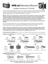
Correct
concrete
concrete
plaster/
drywall
plaster/
drywall
Incorrect
Cutaway View
Figure 2
Drill holes and
insert anchors.
Place wall arm
assembly plate
over anchor and
secure with
lag bolt.
Tighten all
lag bolts.
Wall Arm
Concrete
Wall
Lag Bolt
Figure 3
Use the screw slot in the
wall bracket for tem-
porary hanging during
installation.
Figure 1
Figure 4