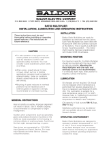
BALDOR ELECTRIC COMPANY
p. o. box 2400 • fort smith, arkansas 72902-2400 u.s.a. • (479) 646-4711 • fax (479) 648-5792
RATIO MULTIPLIER
INSTALLATION, LUBRICATION AND OPERATION INSTRUCTION
Recommender*
Lubricant
Ambient
Temperature
ISO Viscosity
Grade No.
*Mobil SHC634 -30° to 225°F 230/460
Mobil 600W
cylinder oil
40° to 90°F 460
Mobil Extra
helical super
cylinder oil
80° to 125°F 680
These instructions must be read thoroughly
before installing or operating speed reducers.
File instructions for future reference.
•Forsafeoperationofanygeardrive,all
rotating shafts and auxiliary components
must be shielded to conform with applicable
safetystandards.Youmustconsideroverall
operational system safety at all times.
•Whenusingaspeedreducertoraiseorlower
aload,suchasinhoistingapplications,
provisionmustbemadeforexternalbraking.
Under no conditions should a speed reducer
beconsideredself-locking.
•Mountingofspeedreducersinoverhead
positions may be hazardous.Use of external
guides or supports is strongly recommended
foroverheadmounting.
GENERAL INSTRUCTIONS
Align all shafts accurately. Improper alignment
can result in failure. Use of flexible coupling
is recommended to compensate for slight
misalignment.
Auxiliarydrivecomponents(suchassprockets,
gears and pulleys) should be mounted on the
shafts as close as possible to the housing to
minimizeeffectsofoverhungloads.Avoidforcefits
that might damage bearings or gears.
Geardrivesarenameplatedfor1750RPMInput
Speed and Class IService.ForlowerInputSpeeds
andotherServiceClasses,consultthefactory.
INSTALLATION
BaldorRatioMultipliersarereadyforinstallation
asremovedfromthecarton.Theyincorporate
aninternalexpansionchamber(Bladder),which
eliminates the traditional requirement for a breather.
EachRatioMultiplierhasbeenfilledwithmobil
SHC634Syntheticlubricantatthefactory,theoil
quality is sufficient for any mounting position.
LUBRICATION
Oil changes are not required. Oil should
only be replaced when maintenance is
preformed that requires disassembly. If the
oilisreplaced,useMobilSHC634.
MOUNTING POSITION
Formaximumseallife,theRatioMultiplier
should be mounted with the input shaft as
high as possible. Mounting the Ratio
Multiplier with the input seal vertically
down is not recommended. Ifavertically
downinputshaftpositionisrequired,
consult the factory.
ApacketofFel-ProC5-AAnti-SeizeLubricantis
suppliedwiththeRatioMultiplier.Lubricatethe
motorshaftandkeywiththeanti-seizelubricant
beforeinstallingthemotorontotheRatio
Multiplier.(Oilcapacityinfluidounces RM14oz,
RM2 8 oz.)
OPERATING ENVIRONMENT
BaldorRatioMultipliersaredesignedto
operate in ambient temperatures of -10°F
to 100°F. The oil sump temperatures
oftheRatioMultipliermustnotexceed
200°F Consult the factory for applications
requiring ambient operating temperature
outside this range.
Satisfactory performance may be obtained with
non-synthetic oils and will require more frequent
changes.
CAUTION

“C” FLANGE – HOLLOW BORE WORM STYLE:
step #1. Positionkey
inRatioMultiplierInput
Bore. Apply anti-seize
compound to the motor
shaft.Lineupthekeywith
thekeyslotandslipthe
motorshaftintotheRatio
Multiplier Input Bore.
EXTENDED “C” FLANGE WITH FLEXIBLE COUPLING STYLE:
step #1: Mountonecouplinghalfonmotorshaftsothatthecouplinghalfandendofkeyareflushwithend
ofmotorshaft.(SeeDrawingA)
step #2: Tightencouplingsetscrews.Threadlockingcompoundisrecommendedonallcouplingsetscrews.
Measuredistancefrominnerfaceofcouplingtomotormountingsurface.(SeeDrawingA)
step #3: Mount other coupling half on the reducer input shaft so the coupling end measures the same
distancetothemountingsurfaceofthe“C”flange.(SeeDrawingB)Tightensetscrews.Keyshould
beflushwithshaftend.Usepipeplugopeninginsideof“C”flangetoloosen,tightenormakeany
adjustments in coupling position.
step #4: Aligncouplinghalvesandinstallmotor.
step #5: Rotatemotortorequiredpositionandtightenthesuppliedfourboltsandlockwashersevenlyfora
solidfitbetweenmotorand“C”flange.Re-installandtightenthepipeplugintheflangeaccesshole.
© Baldor Electric Company Printed in U.S.A.
LT0066A03 3/02 PRINTSHOP 5000
step 2. Tighten the
supplied 4 bolts with
lockwashersevenly
for a solid fit between
motor and “C” flange.
/


