
17-122 rev. 06 01/04
CAUTION
:
NEVER USE SOLVENTS
Cleaners, fuel, paint, sealants, and other products may
contain strong solvents, such as acetone, which attack
many plastics greatly reducing their strength.
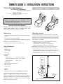
Transom Mount Depth Transducer
or
TRIDUCER
®
Multisensor
with Integral Release Bracket
Models: P23, P32
U. S. Patents: 4,555,938; 4,644,787; 5,606,253; Des. 334,335
Canadian Patent 1,233,341
Applications
•
Not
recommended for boats with large or twin screw inboard
engine(s).
• Good operation up to 55kn (63MPH)
•Vertically orients sound beam on hull with deadrise angle up to 30°
• Adjusts to transom angles from 3
°
–20
°
•Bracket protects sensor from frontal impact only
Tools & Materials
Scissors
Masking tape
Safety goggles
Dust mask
Electric drill
Drill bits:
Bracket holes 4mm, #23,
or
9/64"
Transom hole (optional) 18mm, 11/16",
or
3/4"
Cable clamp holes 3mm
or
1/8"
Straight edge
Wire cutters (some installations)
Marine sealant
Screwdrivers
Pencil
Zip-ties
Water-based antifouling paint (
mandatory in salt water
)
Pretest Temperature & Speed Functions
Check for the approximate air temperature and a speed reading (if
applicable). Connect the sensor to the instrument and spin the
paddlewheel. If there is no reading or it is inaccurate, return the
product to your place of purchase.
Mounting Location
For the best performance, the sensor
must
be in contact with
aeration-free and turbulence-free water. Mount the sensor on the
transom as close to the centerline (keel) of the boat as possible.
On slower, heavier, displacement hulls, positioning it farther from
the centerline is acceptable.
Caution
: Do not mount in an area of turbulence or bubbles:
Near water intake or discharge openings
Behind strakes, struts, fittings, or hull irregularities
Behind eroding paint (an indication of turbulence)
Caution
: Avoid mounting the sensor where the boat may be
supported during trailering, launching, hauling, or storage.
•
Single drive boat
—Mount on the starboard side at least 75mm
(3") beyond the swing radius of the propeller (see Figure 1).
•
Twin drive boat
—Mount the sensor between the drives.
OWNER’S GUIDE & INSTALLATION INSTRUCTIONS
Record the information found on the cable tag for future reference.
Part No._________________Date___________Frequency________kHz
IMPORTANT
: Please read the instructions completely
before proceeding with the installation. These
instructions supersede any other instructions in your
instrument manual if they differ.
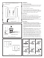
Figure 1. Mounting location on single drive boat
75mm (3")
minimum beyond
swing radius
AIRMAR
®
P23
P32

Installation
Assembling & Positioning
1. Insert the top of the sensor’s pivot posts into the slots on the top
back of the bracket. Rotate the bracket down until the bottom
snaps onto the sensor.
2. Cut out the template (see Figure 2).
3. At the selected location on the starboard side of the hull,
position the template so the arrow at the bottom is aligned with
the bottom edge of the transom (see Figure 3).
Being sure
the
template is parallel to the waterline, tape it in place.
Hole Drilling
Warning
: Always wear safety goggles and a dust mask.
Using a 4mm, #23, or 9/64" bit, drill two holes 22mm (7/8") deep
at the locations indicated. To prevent drilling too deeply, wrap
masking tape around the bit 22mm (7/8") from the point.
Fiberglass hull
—Minimize surface cracking by running the drill in
reverse until the gelcoat is penetrated.
Plastic Shims
•
Standard transom
(13° transom angle)—The bracket is
designed for a standard 13° transom angle. The
9 degree
shim
is
not
needed for this installation. If your boat is capable of
speeds above 35kn (40MPH), install the bracket with the
4.5
degree
shim, taper
down
(see Figures 4 and 5). This ensures
that the paddlewheel will be in contact with the water at high
speeds.
•
Stepped transom and jet boats
(3° transom angle) —Use the
9 degree
shim with the taper
down
(see Figures 4 and 5).
•
Small aluminum and fiberglass boats
(20° transom angle)—
Use the
9 degree
shim with the taper
up
(see Figures 4 and 5).
•
If you are unsure about using the shims
—To determine if the
9 degree
shim is needed, position the sensor at the selected
location. Using a straight edge, sight the underside of the
sensor relative to the underside of the hull (see Figures 4 and
5). The stern of the sensor should be 1–3mm (1/16–1/8")
below the bow of the sensor or parallel to the bottom of the hull.
2
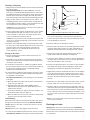
Figure 2. Template for starboard side of boat
centerline (keel)
parallel to waterline
vertical
Align this point with
bottom of transom
drill here
drill here
Figure 3. Template position
Align template arrow with
bottom edge of transom
Align template vertically
parallel to
waterline
Figure 4. Plastic shims
thin shim
thick shim
13
°
transom angle
14
°
–
17
°
angle
Figure 5. Sensor angle adjustment
20
°
transom angle3
°
transom angle
parallel
slight angle
angle
reversed
angle
too steep
slight angle
slight angle
shim with taper down shim with taper up
AIRMAR
®
AIRMAR
®
AIRMAR
®

Mounting & Adjusting
1. Align the posts on the shim with the two holes in the bracket. Snap
the shim into place.
High-speed operation
[above 35kn (40MPH)]—It may be
necessary to install the bracket with both shims to ensures that
the paddlewheel will be in contact with the water at high speeds.
Remove the posts from the 4.5 degree shim with wire cutters.
Place the 4.5 degree shim, taper
down
, behind the 9 degree shim.
2. Apply a marine sealant to the threads of the two #10 x 1-1/4"
self-tapping bracket screws to prevent water seepage into the
transom. With the shim(s) in place, screw the bracket to the hull.
Do not
tighten the screws completely at this time.
Caution
: Do not position the bow of the sensor lower than the
stern because aeration will occur.
3. Using a straight edge, sight the underside of the sensor relative
to the underside of the hull (see Figure 5). The stern of the
sensor should be 1–3mm (1/16–1/8") below the bow of the
sensor or parallel to the bottom of the hull.
Caution
: Do not position the sensor farther into the water than
necessary to avoid increasing drag, spray, and water noise and
reducing boat speed.
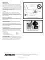
4. Using the vertical adjustment space in the bracket slots, slide
the sensor up or down until the bottom left corner of the sensor
projections 3mm (1/8") below the bottom of the hull (see
Figure 6). When you are satisfied with the position of the
sensor, tighten the screws.
Testing on the Water
1. Become familiar with your echosounder’s performance at a
speed of 4kn (5MPH).
2. Gradually increase the boat speed and observe the gradual
decline in performance due to turbulent water flowing over the
transducer’s active surface.
3. If the decline in performance is sudden (not gradual), identify
the boat speed at which the onset occurred. Return the boat to
this speed, then gradually increase speed while making
moderate turns in both directions.
4. If the performance improves while turning to the side on which
the sensor is installed, its position probably needs adjustment.
It is probably in aerated water.
To improve performance
, try the following
one at a time
in the
order given.
A. Move the multisensor farther into the water in increments of
3mm (1/8") (see Figure 4).
B. High-speed operation above 35kn (40MPH) may be
improved by less projection in the water. Move the sensor
upward on the transom.
C. Increase the multisensor’s angle in the water. Install the 4.5
•
shim with the taper
down
(see Figure 5).
D. Move the multisensor closer to the centerline of the boat. Fill
unused screw holes with marine sealant.
Cable Routing
Route the sensor cable over the transom, through a drain hole or
through a new hole drilled in the transom
above the waterline
.
Caution
: Never cut the cable or remove the connector; this will
void the warranty
.
Warning
: Always wear safety goggles and a dust mask.
1. If a hole must be drilled through the transom, choose a location
well above the waterline
(see Figure 6). Check for obstructions
such as trim tabs, pumps or wiring inside the hull. Mark the
location with a pencil. Drill a hole using the appropriate size bit
to accommodate the connector.
2. Route the cable over or through the transom.
3. On the outside of the hull secure the cable against the transom
using the cable clamps. Position one cable clamp 50mm (2")
above the bracket and mark the mounting hole with a pencil.
4. Position the second cable clamp halfway between the first
clamp and the cable hole. Mark this mounting hole.
5. If a hole has been drilled in the transom, open the appropriate
slot in the cable cover. Position the cover over the cable where it
enters the hull. Mark the two screw holes.
6. At each of the marked locations, use a 3mm or 1/8" bit to drill a
hole 10mm (3/8") deep. To prevent drilling too deeply, wrap
masking tape around the bit 10mm (3/8") from the point.
7. Apply marine sealant to the threads of the #6 x 1/2" self-tapping
screws to prevent water from seeping into the transom. If you
have drilled a hole through the transom, apply marine sealant to
the space around the cable where it passes through the
transom.
8. Position the two cable clamps and fasten them in place. If used,
push the cable cover over the cable and screw it in place.
9. Route the cable to the instrument
being careful
not to tear the
cable jacket when passing it through the bulkhead(s) and other
parts of the boat. To reduce electrical interference, separate the
sensor cable from other electrical wiring and the engine(s). Coil
any excess cable and secure it in place with zip-ties to prevent
damage.
10.Refer to your echosounder owner’s manual to connect the
sensor to the instrument.
Checking for Leaks
Warning
: When the boat is placed in the water,
immediately
check for leaks around the screws and any holes drilled in the hull.
Never install a sensor and leave the boat in the water unchecked
for several days.
3
Figure 6. Vertical adjustment and cable routing
50mm (2")
cable cover
cable clamp
Hull projection:
3mm (1/8")
AIRMAR
®

AIRMAR
®
TECHNOLOGY CORPORATION
35 Meadowbrook Drive, Milford, New Hampshire 03055-4613, USA
■
www.airmar.com
4
Copyright 1995. All rights reserved.
Maintenance
Antifouling Paint
Aquatic growth can accumulate rapidly on the sensor’s surface
reducing performance within weeks. Surfaces exposed to salt
water that do not interlock,
must
be coated with antifouling paint.
Use
water-based
antifouling paint only.
Never
use ketone-based
paint, since ketones can attack many types of plastic possibly
causing damage to the transducer. Apply paint every 6 months or
at the beginning of each boating season.
Cleaning
Clean the assembly with a soft cloth and mild household
detergent. If fouling occurs, use a stiff brush or putty knife to
remove the growth
being careful
to avoid making scratches on the
transducer face. In severe cases, wet sand the surface with fine
grade wet/dry paper.
Servicing the Paddlewheel
If the P32 paddlewheel becomes fouled or inoperable, it can be
removed for cleaning. Gently push back one retaining arm and
slide the shaft out.
Caution: The paddlewheel must be oriented correctly to
measure boat speed.
Orient the short side of the paddlewheel blades as shown in
Figure 7. Reinsert the shaft in the lower set of holes by pushing
back on the retaining arms.
Be sure
the shaft ends are secure in
the retaining arm notches.
Parts & Accessories
Replace broken or worn parts immediately. The water-lubricated
paddlewheel bearings have a life of up to 5 years on low-speed
boats [less than 10kn (11MPH)] and 2 years on high-speed
vessels. Purchase parts from your marine dealer or instrument
manufacturer.
Paddlewheel Kit 33-007
Bracket & Wedge Kit 20-154-04
Portable Bracket Kit (see Figure 8) 33-173
Sensor Replacement
The information needed to order a replacement sensor is printed
on the cable tag.
Do not
remove this tag. When ordering, specify
the part number, date, and frequency in kHz. For convenient
reference, record this information on the top of page one.
Figure 8. Portable Bracket Kit 33-173
AIRMAR
®
AIRMAR
®
Figure 7. Orienting the paddlewheel
The paddlewheel
must
be oriented correctly to
measure boat speed.
short side of
paddlewheel blade
retaining
BOW
use lower hole
arm
-
 1
1
-
 2
2
-
 3
3
-
 4
4


Ask a question and I''ll find the answer in the document
Finding information in a document is now easier with AI
Related papers
Other documents
-
Hardy HI6300 Template
-
Airmar P66 Owners And Installation Manual
-
Airmar P23, P32 TRIDUCER Multisensor Owner's manual
-
-
-
-
-
-
-
Airmar P39 Owner's Manual & Installation Instructions