MODELS QP330BL • QP330SS • QP330WW
QP336BL • QP336SS • QP336WW
QP342BL • QP342SS • QP342WW
Page 8
SERVICE PARTS
KEY NO. PART NO. DESCRIPTION
1 97017727 7” Round Duct Plate (includes mounting hardware)
2 97018256 User Interface Assembly White (includes interface,
nameplate, mounting hardware)
97018257 User Interface Assembly Black (includes interface,
nameplate, mounting hardware)
3 99528258 Nameplate, White
99528259 Nameplate, Black
4 97018251 Capacitor Kit (includes wire nuts, mounting screw)
5 97018225 Light Panel RH White (includes mounting hardware)
97018226 Light Panel RH Black (includes mounting hardware)
97018227 Light Panel RH Stainless (includes mounting hardware)
6 97018205 Filter Kit for 30” (2 per bag)
97018206 Filter Kit for 36” (2 per bag)
97018207 Filter Kit for 42” (3 per bag)
7 97018220 Blower Wheel (includes mounting nut)
8 97018223 Motor Kit (includes motor, isolators, mounting hardware)
9 97017728 Damper / Duct Connector (includes mounting hardware)
10 97018229 Light Panel LH White (includes mounting hardware)
97018230 Light Panel LH Black (includes mounting hardware)
97018231 Light Panel LH Stainless (includes mounting hardware)
11 97017731
Lamp Socket (includes lamp socket, wire nuts, mounting screws)
12 97018233 Lamp Socket Bracket
13 97018239 Bottom Pan 30” (includes mounting hardware)
97018240 Bottom Pan 36” (includes mounting hardware)
97018241 Bottom Pan 42” (includes mounting hardware)
14 97018242 Non-duct Plenum (includes gasket & mounting hardware)
15 97018243 Non-duct Diverter (includes mounting hardware)
16 97018244 Non-duct Plate (includes mounting hardware)
17 97018260 Circuit Board
18 97018262 Transformer (includes mounting hardware)
Not Shown
97018224 Parts Bag
Not Shown
99010353
Non-Duct Filter Kit for 30” (2 charcoal filters and 8 filter clips)
99010354
Non-Duct Filter Kit for 36” (2 charcoal filters and 8 filter clips)
99010360
Non-Duct Filter Kit for 42” (3 charcoal filters and 12 filter clips)
Not Shown
99526707 Suction Cup Tool
Not Shown
97018252 Heat Sensor
Not Shown
97018253 Fuse
Not Shown
97018261 Ribbon Cable Kit (contains 3)
1
10
2
3
14
16
15
13
6
8
7
9
11
12
4
17
5
18
Order replacement parts by PART NO. - not by KEY NO.
21 DUCTED INSTALLATION ONLY:
Re-install aluminum filters removed in Step 5.
NON-DUCTED INSTALLATION ONLY:
Install aluminum filters and non-ducted filters - purchased
and assembled in Step 11.
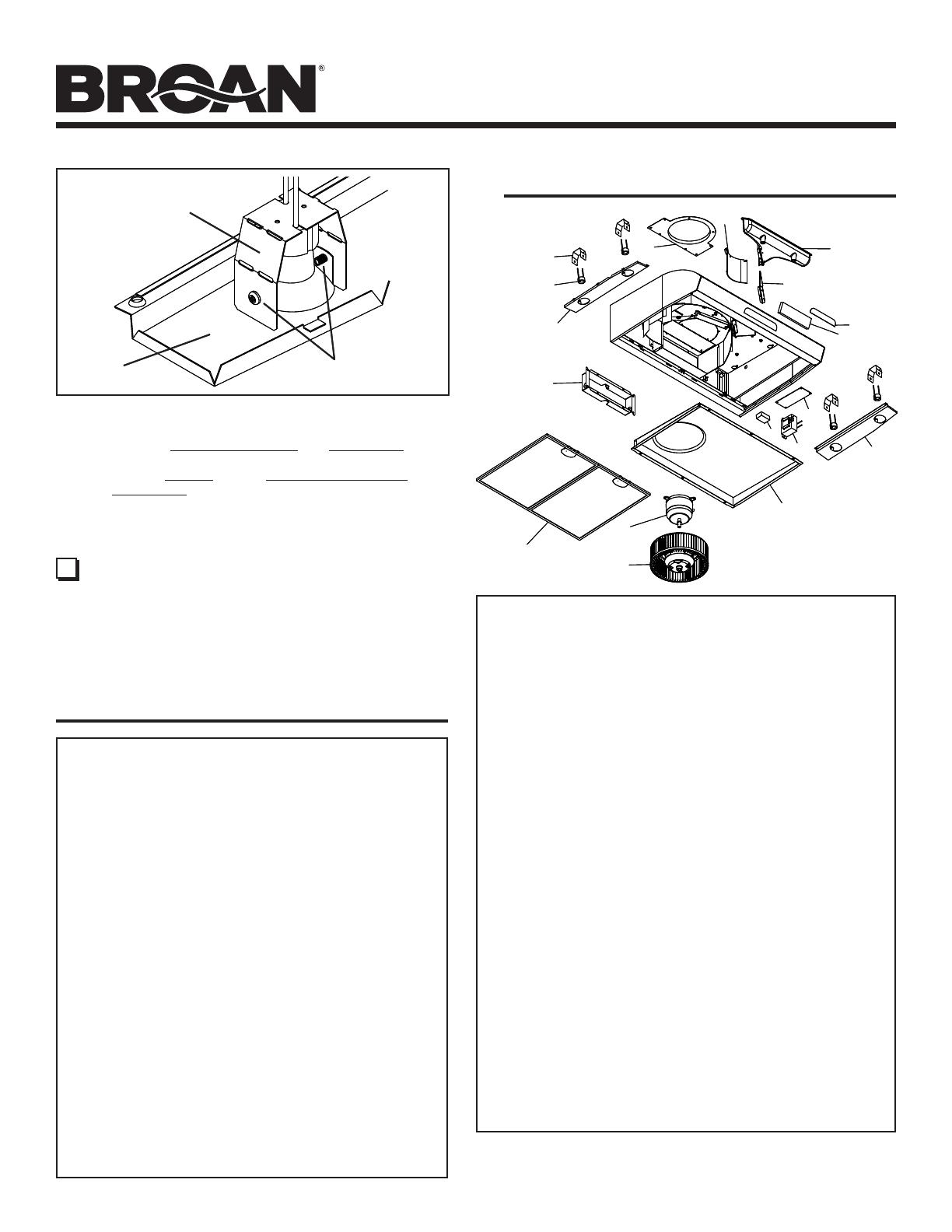
To change the depth of bulb sockets:
- Remove bottom pan (See Step 6).
- Remove 2 Light Panel Screws and Light Panel. Set
screws aside.
- Loosen 2 Screws holding Lamp Socket Bracket to
Light Panel.
- Adjust socket/bracket to desired depth.
- Re-tighten screws securely.
- Re-attach light panel and bottom pan.
LAMP SOCKET
BRACKET
SCREWS
LIGHT
PANEL
WARRANTY
One Year Limited Warranty
Broan-NuTone warrants to the original consumer purchaser of its products that such
products will be free from defects in materials or workmanship for a period of one
(1) year from the date of original purchase. THERE ARE NO OTHER WARRANTIES,
EXPRESS OR IMPLIED, INCLUDING, BUT NOT LIMITED TO, IMPLIED WARRANTIES
OF MERCHANTABILITY OR FITNESS FOR A PARTICULAR PURPOSE.
During this one year period, Broan-NuTone will, at its option, repair or replace, without
charge, any product or part which is found to be defective under normal use and
service. THIS WARRANTY DOES NOT EXTEND TO FLUORESCENT LAMP STARTERS,
TUBES, HALOGEN AND INCANDESCENT BULBS, FUSES, FILTERS, DUCTS, ROOF
CAPS, WALL CAPS AND OTHER ACCESSORIES FOR DUCTING. This warranty does
not cover (a) normal maintenance and service or (b) any products or parts which have
been subject to misuse, negligence, accident, improper maintenance or repair (other
than by Broan-NuTone), faulty installation or installation contrary to recommended
installation instructions.
The duration of any implied warranty is limited to the one year period as specified for the
express warranty. Some states do not allow limitation on how long an implied warranty
lasts, so the above limitation may not apply to you.
BROAN-NUTONE’S OBLIGATION TO
REPAIR OR REPLACE, AT BROAN-NUTONE’S
OPTION, SHALL BE THE PURCHASER’S SOLE AND EXCLUSIVE REMEDY UNDER
THIS WARRANTY. BROAN-NUTONE SHALL NOT BE LIABLE FOR INCIDENTAL,
CONSEQUENTIAL OR SPECIAL DAMAGES ARISING OUT OF OR IN CONNECTION
WITH PRODUCT USE OR PERFORMANCE. Some states do not allow the exclusion or
limitation of incidental or consequential damages, so the above limitation or exclusion
may not apply to you. This warranty gives you specific legal rights, and you may also
have other rights, which vary from state to state. This warranty supersedes all prior
warranties.
To qualify for warranty service, you must (a) notify Broan-NuTone at the address or
telephone number below, (b) give the model number and part identification and (c)
describe the nature of any defect in the product or part. At the time of requesting
warranty service, you must present evidence of the original purchase date.
Broan-NuTone LLC, 926 W. State Street, Hartford, Wisconsin 53027
www.broan.com 800-558-1711
Broan-NuTone Canada, Inc., 1140 Tristar Drive, Mississauga, Ontario Canada L5T 1H9
www.broan.ca 877-896-1119 Rev. 08/2007
SERVICE PARTS
KEY NO. PART NO. DESCRIPTION
1 97017727 7” Round Duct Plate (includes mounting hardware)
2 97018256 User Interface Assembly White (includes interface,
nameplate, mounting hardware)
97018257 User Interface Assembly Black (includes interface,
nameplate, mounting hardware)
3 99528258 Nameplate, White
99528259 Nameplate, Black
4 97018251 Capacitor Kit (includes wire nuts, mounting screw)
5 97018225 Light Panel RH White (includes mounting hardware)
97018226 Light Panel RH Black (includes mounting hardware)
97018227 Light Panel RH Stainless (includes mounting hardware)
6 97018205 Filter Kit for 30” (2 per bag)
97018206 Filter Kit for 36” (2 per bag)
97018207 Filter Kit for 42” (3 per bag)
7 97018220 Blower Wheel (includes mounting nut)
8 97018223 Motor Kit (includes motor, isolators, mounting hardware)
9 97017728 Damper / Duct Connector (includes mounting hardware)
10 97018229 Light Panel LH White (includes mounting hardware)
97018230 Light Panel LH Black (includes mounting hardware)
97018231 Light Panel LH Stainless (includes mounting hardware)
11 97017731
Lamp Socket (includes lamp socket, wire nuts, mounting screws)
12 97018233 Lamp Socket Bracket
13 97018239 Bottom Pan 30” (includes mounting hardware)
97018240 Bottom Pan 36” (includes mounting hardware)
97018241 Bottom Pan 42” (includes mounting hardware)
14 97018242 Non-duct Plenum (includes gasket & mounting hardware)
15 97018243 Non-duct Diverter (includes mounting hardware)
16 97018244 Non-duct Plate (includes mounting hardware)
17 97018260 Circuit Board
18 97018262 Transformer (includes mounting hardware)
Not Shown
97018224 Parts Bag
Not Shown
99010353
Non-Duct Filter Kit for 30” (2 charcoal filters and 8 filter clips)
99010354
Non-Duct Filter Kit for 36” (2 charcoal filters and 8 filter clips)
99010360
Non-Duct Filter Kit for 42” (3 charcoal filters and 12 filter clips)
Not Shown
99526707 Suction Cup Tool
Not Shown
97018252 Heat Sensor
Not Shown
97018253 Fuse
Not Shown
97018261 Ribbon Cable Kit (contains 3)
99527291C
1
10
2
3
14
16
15
13
6
8
7
9
11
12
4
17
5
18
Order replacement parts by PART NO. - not by KEY NO.
21 DUCTED INSTALLATION ONLY:
Re-install aluminum filters removed in Step 5.
NON-DUCTED INSTALLATION ONLY:
Install aluminum filters and non-ducted filters - purchased
and assembled in Step 11.
To change the depth of bulb sockets:
- Remove bottom pan (See Step 6).
- Remove 2 Light Panel Screws and Light Panel. Set
screws aside.
- Loosen 2 Screws holding Lamp Socket Bracket to
Light Panel.
- Adjust socket/bracket to desired depth.
- Re-tighten screws securely.
- Re-attach light panel and bottom pan.
LAMP SOCKET
BRACKET
SCREWS
LIGHT
PANEL
WARRANTY
One Year Limited Warranty
Broan-NuTone warrants to the original consumer purchaser of its products that such
products will be free from defects in materials or workmanship for a period of one
(1) year from the date of original purchase. THERE ARE NO OTHER WARRANTIES,
EXPRESS OR IMPLIED, INCLUDING, BUT NOT LIMITED TO, IMPLIED WARRANTIES
OF MERCHANTABILITY OR FITNESS FOR A PARTICULAR PURPOSE.
During this one year period, Broan-NuTone will, at its option, repair or replace, without
charge, any product or part which is found to be defective under normal use and
service. THIS WARRANTY DOES NOT EXTEND TO FLUORESCENT LAMP STARTERS,
TUBES, HALOGEN AND INCANDESCENT BULBS, FUSES, FILTERS, DUCTS, ROOF
CAPS, WALL CAPS AND OTHER ACCESSORIES FOR DUCTING. This warranty does
not cover (a) normal maintenance and service or (b) any products or parts which have
been subject to misuse, negligence, accident, improper maintenance or repair (other
than by Broan-NuTone), faulty installation or installation contrary to recommended
installation instructions.
The duration of any implied warranty is limited to the one year period as specified for the
express warranty. Some states do not allow limitation on how long an implied warranty
lasts, so the above limitation may not apply to you.
BROAN-NUTONE’S OBLIGATION TO
REPAIR OR REPLACE, AT BROAN-NUTONE’S
OPTION, SHALL BE THE PURCHASER’S SOLE AND EXCLUSIVE REMEDY UNDER
THIS WARRANTY. BROAN-NUTONE SHALL NOT BE LIABLE FOR INCIDENTAL,
CONSEQUENTIAL OR SPECIAL DAMAGES ARISING OUT OF OR IN CONNECTION
WITH PRODUCT USE OR PERFORMANCE. Some states do not allow the exclusion or
limitation of incidental or consequential damages, so the above limitation or exclusion
may not apply to you. This warranty gives you specific legal rights, and you may also
have other rights, which vary from state to state. This warranty supersedes all prior
warranties.
To qualify for warranty service, you must (a) notify Broan-NuTone at the address or
telephone number below, (b) give the model number and part identification and (c)
describe the nature of any defect in the product or part. At the time of requesting
warranty service, you must present evidence of the original purchase date.
Broan-NuTone LLC, 926 W. State Street, Hartford, Wisconsin 53027
www.broan.com 800-558-1711
Broan-NuTone Canada, Inc., 1140 Tristar Drive, Mississauga, Ontario Canada L5T 1H9
www.broan.ca 877-896-1119 Rev. 08/2007


